EP0331601A2 - Windturbine - Google Patents
Windturbine Download PDFInfo
- Publication number
- EP0331601A2 EP0331601A2 EP89500025A EP89500025A EP0331601A2 EP 0331601 A2 EP0331601 A2 EP 0331601A2 EP 89500025 A EP89500025 A EP 89500025A EP 89500025 A EP89500025 A EP 89500025A EP 0331601 A2 EP0331601 A2 EP 0331601A2
- Authority
- EP
- European Patent Office
- Prior art keywords
- mesh
- bearing
- strips
- generator
- framework
- Prior art date
- Legal status (The legal status is an assumption and is not a legal conclusion. Google has not performed a legal analysis and makes no representation as to the accuracy of the status listed.)
- Withdrawn
Links
Images


Classifications
-
- F—MECHANICAL ENGINEERING; LIGHTING; HEATING; WEAPONS; BLASTING
- F03—MACHINES OR ENGINES FOR LIQUIDS; WIND, SPRING, OR WEIGHT MOTORS; PRODUCING MECHANICAL POWER OR A REACTIVE PROPULSIVE THRUST, NOT OTHERWISE PROVIDED FOR
- F03D—WIND MOTORS
- F03D3/00—Wind motors with rotation axis substantially perpendicular to the air flow entering the rotor
- F03D3/06—Rotors
- F03D3/062—Rotors characterised by their construction elements
- F03D3/066—Rotors characterised by their construction elements the wind engaging parts being movable relative to the rotor
- F03D3/067—Cyclic movements
-
- F—MECHANICAL ENGINEERING; LIGHTING; HEATING; WEAPONS; BLASTING
- F05—INDEXING SCHEMES RELATING TO ENGINES OR PUMPS IN VARIOUS SUBCLASSES OF CLASSES F01-F04
- F05B—INDEXING SCHEME RELATING TO WIND, SPRING, WEIGHT, INERTIA OR LIKE MOTORS, TO MACHINES OR ENGINES FOR LIQUIDS COVERED BY SUBCLASSES F03B, F03D AND F03G
- F05B2240/00—Components
- F05B2240/20—Rotors
- F05B2240/21—Rotors for wind turbines
- F05B2240/211—Rotors for wind turbines with vertical axis
- F05B2240/218—Rotors for wind turbines with vertical axis with horizontally hinged vanes
-
- F—MECHANICAL ENGINEERING; LIGHTING; HEATING; WEAPONS; BLASTING
- F05—INDEXING SCHEMES RELATING TO ENGINES OR PUMPS IN VARIOUS SUBCLASSES OF CLASSES F01-F04
- F05B—INDEXING SCHEME RELATING TO WIND, SPRING, WEIGHT, INERTIA OR LIKE MOTORS, TO MACHINES OR ENGINES FOR LIQUIDS COVERED BY SUBCLASSES F03B, F03D AND F03G
- F05B2240/00—Components
- F05B2240/20—Rotors
- F05B2240/21—Rotors for wind turbines
- F05B2240/221—Rotors for wind turbines with horizontal axis
-
- F—MECHANICAL ENGINEERING; LIGHTING; HEATING; WEAPONS; BLASTING
- F05—INDEXING SCHEMES RELATING TO ENGINES OR PUMPS IN VARIOUS SUBCLASSES OF CLASSES F01-F04
- F05B—INDEXING SCHEME RELATING TO WIND, SPRING, WEIGHT, INERTIA OR LIKE MOTORS, TO MACHINES OR ENGINES FOR LIQUIDS COVERED BY SUBCLASSES F03B, F03D AND F03G
- F05B2240/00—Components
- F05B2240/20—Rotors
- F05B2240/30—Characteristics of rotor blades, i.e. of any element transforming dynamic fluid energy to or from rotational energy and being attached to a rotor
- F05B2240/31—Characteristics of rotor blades, i.e. of any element transforming dynamic fluid energy to or from rotational energy and being attached to a rotor of changeable form or shape
- F05B2240/312—Characteristics of rotor blades, i.e. of any element transforming dynamic fluid energy to or from rotational energy and being attached to a rotor of changeable form or shape capable of being reefed
- F05B2240/3121—Characteristics of rotor blades, i.e. of any element transforming dynamic fluid energy to or from rotational energy and being attached to a rotor of changeable form or shape capable of being reefed around an axis orthogonal to rotor rotational axis
-
- F—MECHANICAL ENGINEERING; LIGHTING; HEATING; WEAPONS; BLASTING
- F05—INDEXING SCHEMES RELATING TO ENGINES OR PUMPS IN VARIOUS SUBCLASSES OF CLASSES F01-F04
- F05B—INDEXING SCHEME RELATING TO WIND, SPRING, WEIGHT, INERTIA OR LIKE MOTORS, TO MACHINES OR ENGINES FOR LIQUIDS COVERED BY SUBCLASSES F03B, F03D AND F03G
- F05B2260/00—Function
- F05B2260/70—Adjusting of angle of incidence or attack of rotating blades
- F05B2260/72—Adjusting of angle of incidence or attack of rotating blades by turning around an axis parallel to the rotor centre line
-
- F—MECHANICAL ENGINEERING; LIGHTING; HEATING; WEAPONS; BLASTING
- F05—INDEXING SCHEMES RELATING TO ENGINES OR PUMPS IN VARIOUS SUBCLASSES OF CLASSES F01-F04
- F05B—INDEXING SCHEME RELATING TO WIND, SPRING, WEIGHT, INERTIA OR LIKE MOTORS, TO MACHINES OR ENGINES FOR LIQUIDS COVERED BY SUBCLASSES F03B, F03D AND F03G
- F05B2260/00—Function
- F05B2260/70—Adjusting of angle of incidence or attack of rotating blades
- F05B2260/74—Adjusting of angle of incidence or attack of rotating blades by turning around an axis perpendicular the rotor centre line
-
- Y—GENERAL TAGGING OF NEW TECHNOLOGICAL DEVELOPMENTS; GENERAL TAGGING OF CROSS-SECTIONAL TECHNOLOGIES SPANNING OVER SEVERAL SECTIONS OF THE IPC; TECHNICAL SUBJECTS COVERED BY FORMER USPC CROSS-REFERENCE ART COLLECTIONS [XRACs] AND DIGESTS
- Y02—TECHNOLOGIES OR APPLICATIONS FOR MITIGATION OR ADAPTATION AGAINST CLIMATE CHANGE
- Y02E—REDUCTION OF GREENHOUSE GAS [GHG] EMISSIONS, RELATED TO ENERGY GENERATION, TRANSMISSION OR DISTRIBUTION
- Y02E10/00—Energy generation through renewable energy sources
- Y02E10/70—Wind energy
- Y02E10/74—Wind turbines with rotation axis perpendicular to the wind direction
Definitions
- the invention referred to herein is a simple wind generator which allows greater use to be made of wind action.
- Wind generators are used as motors in electricity production, water lifting, and an infinite number of industrial processes.
- the invention described herein is a wind generator of a simple, economical composition which can also use different wind strengths, even should winds be quite slight, making installation of this generator feasible in areas having low winds. This invention also has a longer period of operation.
- this invention Due to its large wind-catching surface, this invention has a strong starting power and high output.
- Another advantage offered by this generator is its system of self-protection against high-strength winds.
- This generator is composed of a rotating shaft along which two or more radial sails are mounted at equidistant angles.
- Each sail is comprised of a piece of supporting mesh and a series of self-orienting, flexible strips.
- On one end of the aforementioned shaft is a geared ring that enmeshes with a power supply pinion.
- Each piece of mesh is mounted on a flat framework having the same shape as the sails.
- the flexible strips of each sail are mounted on a flat framework independent of the mesh-bearing framework.
- the strips are layered consecutively on the framework so as to cover its entire surface. These strips are attached to the framework along only one of their edges, for example, by means of a rotating shaft.
- the frameworks bearing the flexible strips are located alongside or close to the frameworks bearing the mesh and are located on the same side of said mesh on each sail.
- the rotating shaft may be vertical or horizontal, and is comprised of either a rigid, rotating bar to which the frameworks bearing the mesh and the strips are attached, or a tubular, rotating shaft mounted on a rigid, fixed shaft.
- the rotating shaft could also be comprised of a set of freely-rotating bearings or rings mounted on a rigid bar, with the frameworks bearing the mesh and strips attached to said bearings or rings.
- the mesh-bearing framework may be moved at an angle to the strip-bearing framework, and the two frameworks are attached to each other by elastic or motorized elements that regulate the separation between them according to wind strength or intensity.
- elastic or motorized elements that regulate the separation between them according to wind strength or intensity.
- the sails may be triangular, rectangular, trapezial, etc.
- the strips should preferibly be quadrangular (for example, rectangular or trapezial) and the upper horizontal edge of each strip is attached to the framework.
- the strips may also be set at a slant.
- the center area of the mesh of each sail may be left slightly slack, giving a certain concavity to the fabric and increasing output.
- the generator can have flat, transversal, locking surfaces that would increase generator output.
- the strips forming the sails should preferibly be made of fabric.
- the flat frameworks bearing the strips include at least one rigid arm fastened radially to the rotating shaft.
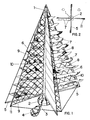
- the generator shown in figures 1 and 2 is comprised of a rotating vertical shaft, indicated by the number 1, the lower portion of which ends in a gear ring, 2, which enmeshes with pinion 3, attached to the shaft of a motor, 4.
- Attached radially to rotating vertical shaft 1 are four rigid arms, indicated by the number 5, whose free end is attached to the top end of shaft 1 by tightened cables, 6.
- the arms (5) and cables (6) form flat, triangular frameworks on which flexible strips, 7, are mounted. Said strips, made, for example, of fabric, are attached to said framework along only one of their edges, preferibly the upper longitudinal edge, 8. Attachment may be by means of a rotating shaft.
- the strips (7) are trapezial, though they be shaped differently.
- the shape of the frameworks (6) may also vary.
- Each sail is comprised of flat frameworks (6) bearing strips (7) and flat frameworks (9) bearing mesh (10).
- the two frameworks are located alongside or close to one another.
- frameworks 6 and 9 occupy the same relative position, in such a way that in all sails the strips (7) are located on the same side of the sail with respect to the mesh (10).
- the mesh (10) may be strung across the same framework on which the sails (7) are mounted.
- mesh-bearing framework 9 and strip-bearing framework 6 are attached to one another by means of an elastic band or element, 11, which pulls framework 9 towards framework 6.
- Figure 3 shows a piece of mesh (10) mounted on its framework (9), which may be the same as the fabric-bearing framework (6).
- Figure 4 shows one example of framework 6, on which strips (7) are mounted.
- the upper edge of the strips may bear a small tube as their upper articulation shaft, 8.
- the cables (6) and the framework bearing the strips are attached at the top to a ring, 12, which may be raised by means of pulley 13 and cable 14, pulling ring 12 along rotating shaft 1 or an auxiliary cable, 15.
- the mechanism shown in figure 5 is comprised of a disk, 16, which rotates when the strength or intensity of the wind increases excessively. Said rotation moves gripping point 17, which is the point where mesh-bearing framework 9 is fastened, and varies the angular separation between mesh-bearing framework 9 and arm 5, which forms part of the framework bearing the flexible strips.
- the rotation of the disk is controlled by spring 18.
- Figure 6 shows a variation of the mechanism described above, in which disk 16 includes an extensor, 19, which moves the lower cable of mesh framework 9 to the position indicated with the number 20 when the strength or intensity of the wind increases.
- figure 8 shows a generator constructed as described above, but in which rotating shaft 1 is horizontal and is mounted by means of bearings on lateral supports, 22.
- the strips, 7, are rectangular, as is the mesh, 10.
- the strips (7) are mounted between rigid arms, 5, on the ends.
Landscapes
- Engineering & Computer Science (AREA)
- Life Sciences & Earth Sciences (AREA)
- Sustainable Development (AREA)
- Sustainable Energy (AREA)
- Chemical & Material Sciences (AREA)
- Combustion & Propulsion (AREA)
- Mechanical Engineering (AREA)
- General Engineering & Computer Science (AREA)
- Wind Motors (AREA)
Applications Claiming Priority (4)
| Application Number | Priority Date | Filing Date | Title |
|---|---|---|---|
| ES8800619 | 1988-03-02 | ||
| ES8800619A ES2010526A6 (es) | 1988-03-02 | 1988-03-02 | Perfeccionamientos en aparatos captadores de energia eolica. |
| ES8803942 | 1988-12-23 | ||
| ES8803942A ES2009482A6 (es) | 1988-12-23 | 1988-12-23 | Generador eolico. |
Publications (2)
| Publication Number | Publication Date |
|---|---|
| EP0331601A2 true EP0331601A2 (de) | 1989-09-06 |
| EP0331601A3 EP0331601A3 (de) | 1989-10-18 |
Family
ID=26154369
Family Applications (1)
| Application Number | Title | Priority Date | Filing Date |
|---|---|---|---|
| EP89500025A Withdrawn EP0331601A3 (de) | 1988-03-02 | 1989-03-02 | Windturbine |
Country Status (1)
| Country | Link |
|---|---|
| EP (1) | EP0331601A3 (de) |
Cited By (6)
| Publication number | Priority date | Publication date | Assignee | Title |
|---|---|---|---|---|
| WO2004065787A1 (de) * | 2003-01-17 | 2004-08-05 | Michael Koelsch | Windkraftanlage mit vertikaler rotorachse |
| DE102004061369A1 (de) * | 2004-09-01 | 2006-07-06 | Prikot, Alexander, Dipl.-Ing. | Windkraftanlage |
| US20120294728A1 (en) * | 2010-11-22 | 2012-11-22 | Randal Stewart | Wind diode systems |
| ITRM20130387A1 (it) * | 2013-07-01 | 2015-01-02 | Salvatore Serravillo | Aerogeneratore ad alto rendimento |
| US9194367B1 (en) * | 2010-04-13 | 2015-11-24 | Phil Feldhaus | Wind turbine |
| GB2560084A (en) * | 2016-12-28 | 2018-08-29 | Shih Yu Huang | Wind harnessing device |
Family Cites Families (4)
| Publication number | Priority date | Publication date | Assignee | Title |
|---|---|---|---|---|
| US3920354A (en) * | 1974-08-30 | 1975-11-18 | Bert J Decker | Horizontal hinged-flap windmill |
| GB2002064A (en) * | 1977-06-21 | 1979-02-14 | Tamarin A | Wins powered rotary machine |
| GB2048391B (en) * | 1979-05-04 | 1983-01-26 | Hunt R P | Rotational drives converting linear fluid flow into rotational movement |
| US4678394A (en) * | 1985-07-30 | 1987-07-07 | Willoughby Francis E | Fluid current driven machine employing individually self-governing energy panels |
-
1989
- 1989-03-02 EP EP89500025A patent/EP0331601A3/de not_active Withdrawn
Cited By (6)
| Publication number | Priority date | Publication date | Assignee | Title |
|---|---|---|---|---|
| WO2004065787A1 (de) * | 2003-01-17 | 2004-08-05 | Michael Koelsch | Windkraftanlage mit vertikaler rotorachse |
| DE102004061369A1 (de) * | 2004-09-01 | 2006-07-06 | Prikot, Alexander, Dipl.-Ing. | Windkraftanlage |
| US9194367B1 (en) * | 2010-04-13 | 2015-11-24 | Phil Feldhaus | Wind turbine |
| US20120294728A1 (en) * | 2010-11-22 | 2012-11-22 | Randal Stewart | Wind diode systems |
| ITRM20130387A1 (it) * | 2013-07-01 | 2015-01-02 | Salvatore Serravillo | Aerogeneratore ad alto rendimento |
| GB2560084A (en) * | 2016-12-28 | 2018-08-29 | Shih Yu Huang | Wind harnessing device |
Also Published As
| Publication number | Publication date |
|---|---|
| EP0331601A3 (de) | 1989-10-18 |
Similar Documents
| Publication | Publication Date | Title |
|---|---|---|
| US4350895A (en) | Wind turbine and method for power generation | |
| US4619585A (en) | Wind turbine apparatus | |
| US5183386A (en) | Vertical axis sail bladed wind turbine | |
| US8258645B2 (en) | Wind turbine with sail extensions | |
| US8109727B2 (en) | Wind turbine | |
| US4684817A (en) | Valvular sail power plant | |
| EP1994279B1 (de) | Windturbine | |
| US5171127A (en) | Vertical axis sail bladed wind turbine | |
| US6402472B1 (en) | Sail-type windmill wheel | |
| EP2486269B1 (de) | Rotorsystem | |
| JP3017172B2 (ja) | 風力発電装置 | |
| EP0331601A2 (de) | Windturbine | |
| GB2264754A (en) | A wind turbine. | |
| JPS55153870A (en) | Vane body for vertical-shaft windmill | |
| US20180106239A1 (en) | Wind Warrior | |
| US20030001393A1 (en) | Linear motion wind driven power generator | |
| EP1331390A2 (de) | Windturbine mit Senkrechter Drehachse | |
| RU98122288A (ru) | Ветроэнергетическая установка | |
| EP0193624A1 (de) | Windkraftantrieb | |
| RU2230932C1 (ru) | Ветроэнергетическая установка (варианты) | |
| RU2114317C1 (ru) | Ветряная электростанция парусная-2 (вэпг - 2) | |
| RU95112906A (ru) | Ветряная электростанция парусная-2 (вэп-2) | |
| JPS57131873A (en) | Liquid energy converting mechanism | |
| EP4656875A1 (de) | Windkraftanlage | |
| DE2812787A1 (de) | Wind- und sonnenkraftmaschine |
Legal Events
| Date | Code | Title | Description |
|---|---|---|---|
| PUAI | Public reference made under article 153(3) epc to a published international application that has entered the european phase |
Free format text: ORIGINAL CODE: 0009012 |
|
| PUAL | Search report despatched |
Free format text: ORIGINAL CODE: 0009013 |
|
| AK | Designated contracting states |
Kind code of ref document: A2 Designated state(s): AT BE CH DE FR GB GR IT LI LU NL SE |
|
| AK | Designated contracting states |
Kind code of ref document: A3 Designated state(s): AT BE CH DE FR GB GR IT LI LU NL SE |
|
| 17P | Request for examination filed |
Effective date: 19900131 |
|
| 17Q | First examination report despatched |
Effective date: 19910307 |
|
| STAA | Information on the status of an ep patent application or granted ep patent |
Free format text: STATUS: THE APPLICATION HAS BEEN WITHDRAWN |
|
| 18W | Application withdrawn |
Withdrawal date: 19910523 |
|
| R18W | Application withdrawn (corrected) |
Effective date: 19910523 |