EP0331559B1 - Aufbausatz zur elektrischen Herabsetzung der Geschwindigkeit und sein elektrische Vorsorgungsmittel - Google Patents
Aufbausatz zur elektrischen Herabsetzung der Geschwindigkeit und sein elektrische Vorsorgungsmittel Download PDFInfo
- Publication number
- EP0331559B1 EP0331559B1 EP89400498A EP89400498A EP0331559B1 EP 0331559 B1 EP0331559 B1 EP 0331559B1 EP 89400498 A EP89400498 A EP 89400498A EP 89400498 A EP89400498 A EP 89400498A EP 0331559 B1 EP0331559 B1 EP 0331559B1
- Authority
- EP
- European Patent Office
- Prior art keywords
- rotor
- stator
- retarder
- alternator
- inductor
- Prior art date
- Legal status (The legal status is an assumption and is not a legal conclusion. Google has not performed a legal analysis and makes no representation as to the accuracy of the status listed.)
- Expired - Lifetime
Links
- 238000001816 cooling Methods 0.000 claims description 10
- 239000007788 liquid Substances 0.000 claims description 9
- 230000005540 biological transmission Effects 0.000 claims description 8
- 230000008878 coupling Effects 0.000 claims description 4
- 238000010168 coupling process Methods 0.000 claims description 4
- 238000005859 coupling reaction Methods 0.000 claims description 4
- 230000005294 ferromagnetic effect Effects 0.000 claims description 2
- 230000005291 magnetic effect Effects 0.000 claims description 2
- 238000009423 ventilation Methods 0.000 claims description 2
- XLYOFNOQVPJJNP-UHFFFAOYSA-N water Substances O XLYOFNOQVPJJNP-UHFFFAOYSA-N 0.000 abstract description 6
- 230000005284 excitation Effects 0.000 description 11
- 210000004027 cell Anatomy 0.000 description 4
- 230000000712 assembly Effects 0.000 description 3
- 238000000429 assembly Methods 0.000 description 3
- 230000000750 progressive effect Effects 0.000 description 2
- 108010053481 Antifreeze Proteins Proteins 0.000 description 1
- 230000002528 anti-freeze Effects 0.000 description 1
- 238000010276 construction Methods 0.000 description 1
- 230000005611 electricity Effects 0.000 description 1
- 239000003302 ferromagnetic material Substances 0.000 description 1
- 238000010438 heat treatment Methods 0.000 description 1
- 238000005192 partition Methods 0.000 description 1
- 238000007789 sealing Methods 0.000 description 1
- 239000007787 solid Substances 0.000 description 1
- 238000004804 winding Methods 0.000 description 1
Images

Classifications
-
- H—ELECTRICITY
- H02—GENERATION; CONVERSION OR DISTRIBUTION OF ELECTRIC POWER
- H02K—DYNAMO-ELECTRIC MACHINES
- H02K49/00—Dynamo-electric clutches; Dynamo-electric brakes
- H02K49/02—Dynamo-electric clutches; Dynamo-electric brakes of the asynchronous induction type
- H02K49/04—Dynamo-electric clutches; Dynamo-electric brakes of the asynchronous induction type of the eddy-current hysteresis type
- H02K49/043—Dynamo-electric clutches; Dynamo-electric brakes of the asynchronous induction type of the eddy-current hysteresis type with a radial airgap
-
- B—PERFORMING OPERATIONS; TRANSPORTING
- B60—VEHICLES IN GENERAL
- B60L—PROPULSION OF ELECTRICALLY-PROPELLED VEHICLES; SUPPLYING ELECTRIC POWER FOR AUXILIARY EQUIPMENT OF ELECTRICALLY-PROPELLED VEHICLES; ELECTRODYNAMIC BRAKE SYSTEMS FOR VEHICLES IN GENERAL; MAGNETIC SUSPENSION OR LEVITATION FOR VEHICLES; MONITORING OPERATING VARIABLES OF ELECTRICALLY-PROPELLED VEHICLES; ELECTRIC SAFETY DEVICES FOR ELECTRICALLY-PROPELLED VEHICLES
- B60L7/00—Electrodynamic brake systems for vehicles in general
- B60L7/10—Dynamic electric regenerative braking
-
- Y—GENERAL TAGGING OF NEW TECHNOLOGICAL DEVELOPMENTS; GENERAL TAGGING OF CROSS-SECTIONAL TECHNOLOGIES SPANNING OVER SEVERAL SECTIONS OF THE IPC; TECHNICAL SUBJECTS COVERED BY FORMER USPC CROSS-REFERENCE ART COLLECTIONS [XRACs] AND DIGESTS
- Y02—TECHNOLOGIES OR APPLICATIONS FOR MITIGATION OR ADAPTATION AGAINST CLIMATE CHANGE
- Y02T—CLIMATE CHANGE MITIGATION TECHNOLOGIES RELATED TO TRANSPORTATION
- Y02T10/00—Road transport of goods or passengers
- Y02T10/60—Other road transportation technologies with climate change mitigation effect
- Y02T10/64—Electric machine technologies in electromobility
Definitions
- the invention relates to assemblies constituted by an electromagnetic retarder intended to brake a vehicle transmission shaft and by its electrical supply means, assemblies comprising a stator traversed by the shaft, which is centered in this stator by means of appropriate guidance, and a rotor which can be secured to the shaft so as to present an external cylindrical face close to an internal cylindrical face of the stator with interposition of a thin air gap, the rotor comprising an inductor, with coils of electric wire , capable of generating by its electrical excitation a magnetic field with alternating distribution in an annular ferromagnetic part of the stator constituting the armature and associated with a liquid cooling circuit, and the electrical supply of the coils being ensured using a polyphase alternator, in particular three-phase, whose armature is part of the above rotor and is connected to said coils by means of a rectifier also forming part of said rotor, the stator ring composed by the inductor poles of the alternator surrounding with a small clearance the rotor armature
- the retarder is mounted on a section of the vehicle transmission shaft concerned, relatively distant from the motor: this section is itself mounted between two ball bearings carried by two transverse flanges delimiting the axial ends of the stator, then in the form of a cylindrical box, and it is connected to the rest of the shaft by two constant velocity joints.
- the rotor of the device is then in the form of a solid core attached to said central shaft section and extended radially outwards by the inductor coils, in small numbers (typically six).
- Such a construction does not lend itself to direct cantilever mounting on the output of the vehicle gearbox, mounting according to which the stator is cantilevered on the casing of the box and the rotor. is mounted in cantilever on a shaft end coming out of said box, this rotor being also secured to an element of a cardan coupling allowing it to be connected to the rest of the transmission shaft.
- the present invention aims, above all, to make the retarders of the above kind as they lend themselves to such a cantilever mounting.
- the assemblies of the kind defined above are essentially characterized, according to the invention, in that the flange is integral with one of the two jaws of a cardan coupling forming part of the shaft and housed at inside the sleeve, jaw itself cantilevered on the end of a section, of said shaft, which comes out of the casing of the vehicle gearbox and is supported by this casing by means of bearings, in that the stator is carried by an openwork bell-shaped framework itself mounted in overhang on said casing and in that the number of inductor coils of the retarder and that of the inductor poles of the alternator are both greater than or equal to twelve.
- the assembly indicated makes it possible to place the stator armature of the retarder, to be cooled by liquid, very close to the vehicle engine and in particular to the normal water cooling circuit thereof.
- the invention includes, apart from these main provisions, certain other provisions which are preferably used at the same time and which will be more explicitly discussed below.
- FIG. 1 of this drawing schematically shows the assembly, established in accordance with the invention, of an electromagnetic retarder of a vehicle and its means of electrical excitation.
- Figure 2 shows the same assembly in perspective view, portions cut away.
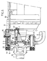
- Figure 3 schematically shows the mounting of such a retarder on the vehicle gearbox.
- the electromagnetic retarder considered is intended to slow down the rotary shaft of a vehicle, preferably of the "heavyweight" type.
- this retarder comprises a rotor 2 secured in rotation with the output shaft 1 of the vehicle gearbox 30 and a stator 3 mounted in cantilever on the casing 31 of this box .
- This annular part 5 is constituted by a cylindrical drum surrounding the inductor with the interposition of a cylindrical air gap E.
- this part 5 is here fixed, it can be easily cooled using a stream of liquid since it is not necessary to have recourse to special seals intended to ensure sealing at the level of connections between two parts in relative movement.
- a liquid circuit 6 is provided for this purpose comprising a section 7 which runs directly along the face of the induced part 5 opposite the air gap E.
- said section 7 is here formed by a pipe extending along a helix around the drum 5, pipe terminated at its two ends by two inlet 8 and outlet 9 fittings.
- Such recesses or reliefs can also be provided on the other walls of said section.
- the circuit section 7 is constituted by a simple annular water jacket delimited by two coaxial cylindrical walls connected to each other on the one hand at their axial ends by two transverse washers and on the other hand by a radial longitudinal partition separating the entrance from the exit.
- the cooling circuit 6 comprises, in addition to the section 7, a drive pump 11 and an external heat exchanger 12, such as a finned radiator, making it possible to dissipate towards the outside the calories carried by the liquid in circulation.
- an external heat exchanger 12 such as a finned radiator
- This liquid is advantageously constituted by water added with anti-freeze.
- the pump 11 and the exchanger 12 are advantageously the water pump and the radiator which form part of the normal cooling circuit of the vehicle engine: it should in fact be noted that, during the operation of the retarder, the engine releases few calories so that its cooling requirements are then reduced; in addition, because the retarder is mounted on the vehicle gearbox 30, it is very close to said normal cooling circuit.
- the axes of the coils 4 which define the inductor poles here extend radially around the axis of the device.
- This inductor being rotary, it is advisable to provide special means for supplying its coils 4 with electric current.
- the multiple poles of the stator are created by a ring of small electromagnets with alternating polarities connected to a source of direct current 15 such as the vehicle battery if the retarder considered equips such a vehicle.
- This circuit 16 advantageously includes a manual control member 17.
- the alternating current collected at the terminals of the rotor 13 is rectified by an appropriate bridge 18 before being applied to the coils 4 of the retarder.
- this armature 13 is secured to the coils 4 of the retarder, all of these elements being mounted on the same sleeve 19 extended internally by a transverse web 20 itself hollowed out by fixing holes 21 and forming a connection flange to a plate 32 secured to the shaft 1.
- This sleeve 19 can form a single piece with cores 4 ′ and with flange 20.
- the plate 32 is in turn secured to one of the two jaws 33 of a cardan coupling, the other jaw 34 of which is secured to the main section 1 ′ of the transmission shaft: as visible in FIG. 3, these two jaws 33 and 34 are freely housed inside the tube formed by the sleeve 19.
- the stator 14 is, for its part, mounted inside a fixed sleeve 22 delimiting the outside of the pipe section 7 above: it is this sleeve 22 which is mounted in cantilever on the casing 31 of the box 30 using an openwork bell frame 35 such as an arm crown.
- the output shaft 1 of the box is rigorously centered in the latter, in particular by means of bearings 36, 37, so that the rotor 2 and the stator 3 are mutually centered and so that the annular air gaps E and e above.
- the number of inductor coils 4 and that of the poles 14 of the generator are relatively high, namely at least equal to twelve, to allow clearing inside the machine of a large diameter space for the passage of the shaft 1 to slow down: in fact, the higher these numbers, the more it is possible to give the corresponding coils and poles small radial lengths; these two numbers are for example here of eighteen and twenty-four respectively.
- this retarder is very easily controlled by simple excitation of the fixed inductor 14 of the generator, excitation which is preferably controlled using the member 17.
Landscapes
- Engineering & Computer Science (AREA)
- Power Engineering (AREA)
- Transportation (AREA)
- Mechanical Engineering (AREA)
- Dynamo-Electric Clutches, Dynamo-Electric Brakes (AREA)
- Braking Arrangements (AREA)
- Endoscopes (AREA)
- Golf Clubs (AREA)
- Braking Systems And Boosters (AREA)
- Organic Insulating Materials (AREA)
Claims (2)
Priority Applications (1)
| Application Number | Priority Date | Filing Date | Title |
|---|---|---|---|
| AT89400498T ATE64040T1 (de) | 1988-02-25 | 1989-02-22 | Aufbausatz zur elektrischen herabsetzung der geschwindigkeit und sein elektrische vorsorgungsmittel. |
Applications Claiming Priority (2)
| Application Number | Priority Date | Filing Date | Title |
|---|---|---|---|
| FR8802301A FR2627913B1 (fr) | 1988-02-25 | 1988-02-25 | Ralentisseur electromagnetique, moyens d'alimentation associes et application a un vehicule |
| FR8802301 | 1988-02-25 |
Publications (2)
| Publication Number | Publication Date |
|---|---|
| EP0331559A1 EP0331559A1 (de) | 1989-09-06 |
| EP0331559B1 true EP0331559B1 (de) | 1991-05-29 |
Family
ID=9363619
Family Applications (1)
| Application Number | Title | Priority Date | Filing Date |
|---|---|---|---|
| EP89400498A Expired - Lifetime EP0331559B1 (de) | 1988-02-25 | 1989-02-22 | Aufbausatz zur elektrischen Herabsetzung der Geschwindigkeit und sein elektrische Vorsorgungsmittel |
Country Status (10)
| Country | Link |
|---|---|
| US (1) | US4864173A (de) |
| EP (1) | EP0331559B1 (de) |
| JP (1) | JP2796334B2 (de) |
| KR (1) | KR970006072B1 (de) |
| AT (1) | ATE64040T1 (de) |
| CA (1) | CA1304439C (de) |
| DE (1) | DE68900087D1 (de) |
| ES (1) | ES2022755B3 (de) |
| FR (1) | FR2627913B1 (de) |
| PT (1) | PT89816B (de) |
Families Citing this family (62)
| Publication number | Priority date | Publication date | Assignee | Title |
|---|---|---|---|---|
| FR2653075B1 (fr) * | 1989-10-17 | 1992-01-24 | Labavia | Perfectionnements aux transmissions de vehicules equipees de ralentisseurs electriques. |
| US5185543A (en) * | 1990-02-27 | 1993-02-09 | Fichtel & Sachs Ag | Motor vehicle drive line torsional vibration damper |
| JPH0415955U (de) * | 1990-05-29 | 1992-02-10 | ||
| FR2667741B1 (fr) * | 1990-10-05 | 1993-01-08 | Labavia | Perfectionnements aux dispositifs pour mesurer les couples de freinage engendres par les ralentisseurs electromagnetiques et aux dispositifs de reglage de ces couples. |
| US5138206A (en) * | 1991-06-04 | 1992-08-11 | Megamation Incorporated | Method and apparatus for cooling hot spots in platen of linear motor system |
| US5347188A (en) * | 1992-09-09 | 1994-09-13 | Sunstrand Corporation | Electric machine with enhanced liquid cooling |
| ES2110861B1 (es) * | 1993-01-29 | 1999-04-01 | Frenos Electricos Unidos Sa | Pieza intercalar para la instalacion de un ralentizador electromagnetico sobre el puente posterior de un vehiculo e instalaciones que comprenden dicha pieza. |
| US5650679A (en) * | 1993-03-18 | 1997-07-22 | Boggs, Iii; Paul Dewey | Eddy current drive |
| US5465018A (en) * | 1993-03-18 | 1995-11-07 | Boggs, Iii; Paul D. | Shaft mounted eddy current drive |
| US5434461A (en) * | 1993-03-18 | 1995-07-18 | Boggs, Iii; Paul D. | Shaft mounted eddy current drive |
| US5627422A (en) * | 1993-03-18 | 1997-05-06 | Paul D. Boggs, III | Shaft mounted eddy current drive |
| US6148967A (en) * | 1998-07-10 | 2000-11-21 | Alliedsignal Inc. | Non-contacting and torquer brake mechanism |
| US6800971B1 (en) * | 1999-06-01 | 2004-10-05 | Robert Bosch Gmbh | Starter generator for an internal combustion engine and method of producing same |
| FR2803134B1 (fr) * | 1999-12-22 | 2002-03-08 | Labinal | Ralentisseur a courants de foucault |
| JP2003521863A (ja) * | 2000-02-02 | 2003-07-15 | パシィフィック サイエンティフィック エレクトロ キネティクス ディビジョン | 一体型リターダおよび付属装置 |
| FR2805937B1 (fr) * | 2000-03-03 | 2002-12-06 | Daniel Drecq | Dispositif de freinage a courants de foucault et echangeur de chaleur pour dispositif de freinage a courants de foucault |
| FR2814003A1 (fr) * | 2000-09-14 | 2002-03-15 | Labinal | Ensemble constitue par un ralentisseur a courants de foucault et par ses moyens d'alimentation electrique |
| US7178644B2 (en) * | 2000-11-27 | 2007-02-20 | Lothar Kloft | Retarder, particularly provided as a braking device or auxiliary braking device for vehicles or the like, especially rail vehicles |
| FR2819351B1 (fr) * | 2001-01-09 | 2003-04-11 | Telma | Ensemble constitue par un ralentisseur electromagnetique et par ses moyens d'alimentation electrique |
| US6581731B2 (en) * | 2001-07-13 | 2003-06-24 | Shui-Jung Chen | Autonomous generation brake assembly |
| AU2003228812A1 (en) * | 2002-05-02 | 2003-11-17 | GMP Surgical Solutions, Inc | Apparatus for positioning a medical instrument |
| FR2842961B1 (fr) * | 2002-07-29 | 2006-03-03 | Telma | Ralentisseur electromagnetique d'un vehicule muni d'un dispositif multiplicateur de vitesse |
| FR2859687A1 (fr) * | 2003-06-27 | 2005-03-18 | Telma | Dispositif de ralentissement pour vehicule automobile et son utilisation |
| US7137673B2 (en) * | 2003-06-27 | 2006-11-21 | Visteon Global Technologies, Inc. | Vehicle yaw stability system and method |
| FR2858724B1 (fr) * | 2003-06-30 | 2006-04-28 | Telma | Ralentisseur electromagnetique d'un vehicule automobile |
| FR2859325A1 (fr) * | 2003-06-30 | 2005-03-04 | Telma | Ralentisseur electromagnetique d'un vehicule automobile |
| FR2860355B1 (fr) * | 2003-09-26 | 2005-12-23 | Telma | Ralentisseur electromagnetique muni d'une zone de degagement |
| FR2861914A1 (fr) * | 2003-10-31 | 2005-05-06 | Telma | Ralentisseur electromagnetique a refroidissement par eau |
| FR2864367B1 (fr) * | 2003-12-19 | 2006-10-27 | Telma | Dispositif de ventilation pour machine electrique tournante autour d'un arbre, a ventilateur independant de l'arbre |
| FR2864370A1 (fr) * | 2003-12-19 | 2005-06-24 | Telma | Ralentisseur electromagnetique comportant des moyens pour creer un courant d'air |
| FR2867914B1 (fr) * | 2004-03-18 | 2006-09-15 | Telma | Canalisation de refroidissement pour une machine electrique rotative, ainsi qu'une machine electrique rotative comprenant une telle canalisation |
| FR2868621A1 (fr) * | 2004-03-31 | 2005-10-07 | Telma Sa | Ralentisseur comportant des pieces pour creer des turbulences |
| FR2872643A1 (fr) * | 2004-06-30 | 2006-01-06 | Valeo Equip Electr Moteur | Chemise de refroidissement pour une machine rotative et machine rotative comportant une telle chemise de refroidissement |
| FR2875968B1 (fr) * | 2004-09-30 | 2007-12-28 | Telma Sa | Ralentisseur electromagnetique refroidi par eau, procede de commande d'un ralentisseur et vehicule automobile comprenant un tel ralentisseur |
| FR2885274B1 (fr) * | 2005-04-29 | 2007-07-27 | Telma Sa | Ventilateur debrayable pour un ralentisseur electromagnetique |
| FR2894091A1 (fr) * | 2005-11-30 | 2007-06-01 | Telma Sa | Procede d'amelioration du refroidissement d'un ralentisseur electromagnetique |
| FR2894411B1 (fr) * | 2005-12-07 | 2008-06-13 | Telma Sa | Procede de pilotage d'un ralentisseur electromagnetique |
| FR2894734B1 (fr) * | 2005-12-09 | 2008-03-14 | Telma Sa | Procede de mise en service d'un ralentisseur electromagnetique |
| FR2895166B1 (fr) * | 2005-12-19 | 2008-06-13 | Telma Sa | Procede de detection de defaut de fobnctionnement d'un ralentisseur electromagnetique |
| FR2895595B1 (fr) * | 2005-12-22 | 2008-03-14 | Telma Sa | Procede de pilotage d'un ralentisseur electromagnetique. |
| FR2895596B1 (fr) * | 2005-12-22 | 2008-03-14 | Telma Sa | Procede de pilotage d'un ralentisseur electromagnetique. |
| AT505585A3 (de) * | 2006-09-08 | 2015-01-15 | Seiwald Andreas | Flüssigkeitsgekühlte wirbelstrombremse |
| FR2918512B1 (fr) * | 2007-05-21 | 2014-03-28 | Valeo Equip Electr Moteur | Machine electrique tournante conformee pour pouvoir fonctionner sous au moins deux tensions electriques differentes |
| DE102009022675A1 (de) * | 2009-05-26 | 2010-12-16 | Horiba Europe Gmbh | Prüfstand mit temperaturgesteuertem Kühlgebläse |
| FR2948243B1 (fr) | 2009-07-17 | 2011-10-07 | Valeo Equip Electr Moteur | Pont redresseur de courant pour alternateur polyphase et alternateur polyphase comportant un tel pont |
| IT1398207B1 (it) * | 2010-02-16 | 2013-02-14 | Alenia Aeronautica Spa | Sistema frenante per carrello di velivolo. |
| DE102010051715A1 (de) * | 2010-11-19 | 2012-05-24 | Voith Patent Gmbh | Antriebsstrang mit einem hydrodynamischen Retarder |
| CN102299608B (zh) * | 2011-07-12 | 2013-10-16 | 北京工业大学 | 一种无电刷构造的液冷自励式电涡流缓速器 |
| DE102011082353B4 (de) * | 2011-09-08 | 2021-04-01 | Siemens Aktiengesellschaft | Stator für einen Elektromotor |
| FR2984626B1 (fr) | 2011-12-20 | 2014-01-17 | Valeo Equip Electr Moteur | Rotor a poles saillants comportant un dispositif d'isolation de bobinages et dispositif d'isolation de bobinages associe |
| FR2984627B1 (fr) | 2011-12-20 | 2016-06-24 | Valeo Equip Electr Moteur | Rotor a poles saillants comportant une piece de guidage de fils de bobinage, piece de guidage de fils de bobinage et procede de bobinage associes |
| US8646550B2 (en) | 2012-05-21 | 2014-02-11 | Krassimire Mihaylov Penev | Self rechargeable synergy drive for a motor vehicle |
| US9067500B2 (en) * | 2012-05-21 | 2015-06-30 | Krassimire Mihaylov Penev | Self rechargeable synergy drive for a motor vehicle |
| US9531242B2 (en) | 2012-12-31 | 2016-12-27 | Teco-Westinghouse Motor Company | Apparatuses and methods for cooling electric machines |
| ES2883341T3 (es) * | 2014-08-14 | 2021-12-07 | Ralentizadores Y Transf S A | Sistema retardador autónomo para un vehículo y vehículo que lo incorpora. |
| CN105790542B (zh) * | 2016-03-25 | 2018-09-14 | 武汉理工大学 | 一种具有能量回收功能的电磁缓速器 |
| US11043875B2 (en) * | 2018-11-20 | 2021-06-22 | GM Global Technology Operations LLC | Temperature control assembly for an electric machine |
| CN113287251A (zh) * | 2019-01-10 | 2021-08-20 | 三菱重工发动机和增压器株式会社 | 马达和逆变器一体型旋转电机 |
| DE102019132942B4 (de) * | 2019-12-04 | 2024-07-25 | Schaeffler Technologies AG & Co. KG | Antriebseinheit und Antriebsanordnung |
| JP7509048B2 (ja) * | 2021-02-02 | 2024-07-02 | トヨタ自動車株式会社 | 電動車両 |
| CN117615932A (zh) * | 2021-07-07 | 2024-02-27 | 拉莱特兹多斯 Y 变压器股份有限公司 | 车辆缓速器供电系统、自主缓速器及自主缓速器制造方法 |
| US12323025B2 (en) * | 2022-10-24 | 2025-06-03 | Schaeffler Technologies AG & Co. KG | Heat exchanger system for an electric motor with fluid circuits arranged between shafts |
Family Cites Families (9)
| Publication number | Priority date | Publication date | Assignee | Title |
|---|---|---|---|---|
| BE569173A (de) * | 1957-12-17 | |||
| US3184626A (en) * | 1961-01-09 | 1965-05-18 | Emerson Electric Co | Eddy current clutch and power supply therefor |
| US3416016A (en) * | 1965-01-11 | 1968-12-10 | Hitachi Ltd | Speed reduction apparatus for automotive vehicles |
| GB1147373A (en) | 1965-09-16 | 1969-04-02 | Labavia | Improvements in or relating to vehicle transmissions including an eddy current retarder |
| US3889140A (en) * | 1968-08-31 | 1975-06-10 | Max Baermann Fa | Induction brake or clutch |
| US4362958A (en) * | 1980-11-03 | 1982-12-07 | Eaton Corporation | Electromagnetic coupling and cooling system therefor |
| US4570094A (en) * | 1984-01-23 | 1986-02-11 | Sundstrand Corporation | Rotating rectifier assembly |
| FR2591297B1 (fr) * | 1985-12-06 | 1990-03-30 | Renault Vehicules Ind | Embrayage ralentisseur. |
| JPH0632503A (ja) * | 1992-07-13 | 1994-02-08 | Konica Corp | 無接触搬送装置 |
-
1988
- 1988-02-25 FR FR8802301A patent/FR2627913B1/fr not_active Expired - Lifetime
-
1989
- 1989-02-17 US US07/311,978 patent/US4864173A/en not_active Expired - Lifetime
- 1989-02-22 EP EP89400498A patent/EP0331559B1/de not_active Expired - Lifetime
- 1989-02-22 DE DE8989400498T patent/DE68900087D1/de not_active Expired - Lifetime
- 1989-02-22 CA CA000591747A patent/CA1304439C/en not_active Expired - Lifetime
- 1989-02-22 AT AT89400498T patent/ATE64040T1/de not_active IP Right Cessation
- 1989-02-22 ES ES89400498T patent/ES2022755B3/es not_active Expired - Lifetime
- 1989-02-23 PT PT89816A patent/PT89816B/pt active IP Right Grant
- 1989-02-23 JP JP1042030A patent/JP2796334B2/ja not_active Expired - Fee Related
- 1989-02-24 KR KR1019890002218A patent/KR970006072B1/ko not_active Expired - Fee Related
Also Published As
| Publication number | Publication date |
|---|---|
| ES2022755B3 (es) | 1991-12-01 |
| EP0331559A1 (de) | 1989-09-06 |
| JPH01255468A (ja) | 1989-10-12 |
| JP2796334B2 (ja) | 1998-09-10 |
| FR2627913B1 (fr) | 1992-02-07 |
| PT89816A (pt) | 1989-10-04 |
| KR970006072B1 (ko) | 1997-04-23 |
| US4864173A (en) | 1989-09-05 |
| KR890012823A (ko) | 1989-09-19 |
| CA1304439C (en) | 1992-06-30 |
| ATE64040T1 (de) | 1991-06-15 |
| DE68900087D1 (de) | 1991-07-04 |
| PT89816B (pt) | 1994-02-28 |
| FR2627913A1 (fr) | 1989-09-01 |
Similar Documents
| Publication | Publication Date | Title |
|---|---|---|
| EP0331559B1 (de) | Aufbausatz zur elektrischen Herabsetzung der Geschwindigkeit und sein elektrische Vorsorgungsmittel | |
| EP1499001B1 (de) | Kühlvorrichtung für eine elektrische Maschine insbesondere für eine Synchronmaschine mit Dauermagneten | |
| FR2916313A1 (fr) | Alternateur de vehicule | |
| FR2872643A1 (fr) | Chemise de refroidissement pour une machine rotative et machine rotative comportant une telle chemise de refroidissement | |
| FR2988236A1 (fr) | Ensemble de flasques de rotor de machine electrique tournante comportant des orifices asymetriques favorisant un flux d'air axial a l'interieur du rotor et rotor de machine electrique tournante associe | |
| EP1155491A1 (de) | Wirbelstrom bremsgerät | |
| EP3782270B1 (de) | Elektrische synchronmaschine | |
| EP3673566A1 (de) | Elektrische maschine mit kühlvorrichtung mit einem teilweise unterteilten kanal | |
| EP1235332B1 (de) | Einheit bestehend aus einer elektromagnetische Bremse und deren elektische Versorgung | |
| EP1527509A1 (de) | Elektromagnetische bremse mit einem geschwindigkeitsvervielfacher für ein kraftfahrzeug | |
| FR2885274A1 (fr) | Ventilateur debrayable pour un ralentisseur electromagnetique | |
| FR2910736A1 (fr) | Stator d'une machine electrique tournante polyphasee, machine electrique tournante polyphasee comportant un tel stator et procede de realisation d'un tel stator | |
| FR2988237A1 (fr) | Ensemble de flasques de rotor de machine electrique tournante munis de pions de centrage et d'evacuation de la chaleur favorisant le refroidissement du rotor et rotor de machine tournante associe | |
| FR2814003A1 (fr) | Ensemble constitue par un ralentisseur a courants de foucault et par ses moyens d'alimentation electrique | |
| FR2859325A1 (fr) | Ralentisseur electromagnetique d'un vehicule automobile | |
| EP4070442B1 (de) | Elektrische fluxgate-maschine mit supraleitende erreger- und ankerwicklung | |
| FR2578117A1 (fr) | Rotor pour machine electrique rotative supraconductrice | |
| FR3071369A1 (fr) | Machine electrique comprenant un stator muni d'un manchon tubulaire interne | |
| EP0244307B1 (de) | Anker von elektromagnetischen Bremsvorrichtungen | |
| WO2020193297A1 (fr) | Rotor de machine electrique avec moyen de ventilation axialo-centrifuge | |
| FR3151444A1 (fr) | Machine électrique à flux axial avec guide thermique entre les bobines du stator | |
| EP2050180A2 (de) | Anordnung für eine elektronische schaltung in einer elektrischen drehmaschine und elektrische drehmaschine mit dieser anordnung | |
| FR2545663A1 (fr) | Carter de moteur de demarreur | |
| WO2026068128A1 (fr) | Systeme de refroidissement par caloduc integre au bobinage d'une machine electrique | |
| FR3153477A1 (fr) | Rotor pour machine électrique à flux axial avec des bras radiaux et des canaux de refroidissement dans les bras radiaux |
Legal Events
| Date | Code | Title | Description |
|---|---|---|---|
| PUAI | Public reference made under article 153(3) epc to a published international application that has entered the european phase |
Free format text: ORIGINAL CODE: 0009012 |
|
| AK | Designated contracting states |
Kind code of ref document: A1 Designated state(s): AT BE CH DE ES FR GB IT LI NL SE |
|
| 17P | Request for examination filed |
Effective date: 19891221 |
|
| 17Q | First examination report despatched |
Effective date: 19900419 |
|
| GRAA | (expected) grant |
Free format text: ORIGINAL CODE: 0009210 |
|
| ITF | It: translation for a ep patent filed | ||
| AK | Designated contracting states |
Kind code of ref document: B1 Designated state(s): AT BE CH DE ES FR GB IT LI NL SE |
|
| REF | Corresponds to: |
Ref document number: 64040 Country of ref document: AT Date of ref document: 19910615 Kind code of ref document: T |
|
| GBT | Gb: translation of ep patent filed (gb section 77(6)(a)/1977) | ||
| REF | Corresponds to: |
Ref document number: 68900087 Country of ref document: DE Date of ref document: 19910704 |
|
| PLBE | No opposition filed within time limit |
Free format text: ORIGINAL CODE: 0009261 |
|
| STAA | Information on the status of an ep patent application or granted ep patent |
Free format text: STATUS: NO OPPOSITION FILED WITHIN TIME LIMIT |
|
| 26N | No opposition filed | ||
| EAL | Se: european patent in force in sweden |
Ref document number: 89400498.5 |
|
| REG | Reference to a national code |
Ref country code: FR Ref legal event code: TP |
|
| PGFP | Annual fee paid to national office [announced via postgrant information from national office to epo] |
Ref country code: DE Payment date: 20010201 Year of fee payment: 13 |
|
| REG | Reference to a national code |
Ref country code: CH Ref legal event code: PFA Free format text: LABAVIA S.G.E. TRANSFER- LABINAL |
|
| REG | Reference to a national code |
Ref country code: GB Ref legal event code: IF02 |
|
| PGFP | Annual fee paid to national office [announced via postgrant information from national office to epo] |
Ref country code: AT Payment date: 20020124 Year of fee payment: 14 |
|
| PGFP | Annual fee paid to national office [announced via postgrant information from national office to epo] |
Ref country code: GB Payment date: 20020125 Year of fee payment: 14 |
|
| PGFP | Annual fee paid to national office [announced via postgrant information from national office to epo] |
Ref country code: SE Payment date: 20020128 Year of fee payment: 14 Ref country code: NL Payment date: 20020128 Year of fee payment: 14 Ref country code: BE Payment date: 20020128 Year of fee payment: 14 Ref country code: CH Payment date: 20020128 Year of fee payment: 14 |
|
| PG25 | Lapsed in a contracting state [announced via postgrant information from national office to epo] |
Ref country code: DE Free format text: LAPSE BECAUSE OF NON-PAYMENT OF DUE FEES Effective date: 20020903 |
|
| REG | Reference to a national code |
Ref country code: FR Ref legal event code: TP |
|
| REG | Reference to a national code |
Ref country code: GB Ref legal event code: 732E |
|
| PG25 | Lapsed in a contracting state [announced via postgrant information from national office to epo] |
Ref country code: GB Free format text: LAPSE BECAUSE OF NON-PAYMENT OF DUE FEES Effective date: 20030222 Ref country code: AT Free format text: LAPSE BECAUSE OF NON-PAYMENT OF DUE FEES Effective date: 20030222 |
|
| PG25 | Lapsed in a contracting state [announced via postgrant information from national office to epo] |
Ref country code: SE Free format text: LAPSE BECAUSE OF NON-PAYMENT OF DUE FEES Effective date: 20030223 |
|
| PG25 | Lapsed in a contracting state [announced via postgrant information from national office to epo] |
Ref country code: BE Free format text: LAPSE BECAUSE OF NON-PAYMENT OF DUE FEES Effective date: 20030228 Ref country code: LI Free format text: LAPSE BECAUSE OF NON-PAYMENT OF DUE FEES Effective date: 20030228 Ref country code: CH Free format text: LAPSE BECAUSE OF NON-PAYMENT OF DUE FEES Effective date: 20030228 |
|
| PG25 | Lapsed in a contracting state [announced via postgrant information from national office to epo] |
Ref country code: NL Free format text: LAPSE BECAUSE OF NON-PAYMENT OF DUE FEES Effective date: 20030901 |
|
| EUG | Se: european patent has lapsed | ||
| GBPC | Gb: european patent ceased through non-payment of renewal fee | ||
| REG | Reference to a national code |
Ref country code: CH Ref legal event code: PL |
|
| NLV4 | Nl: lapsed or anulled due to non-payment of the annual fee |
Effective date: 20030901 |
|
| PG25 | Lapsed in a contracting state [announced via postgrant information from national office to epo] |
Ref country code: IT Free format text: LAPSE BECAUSE OF NON-PAYMENT OF DUE FEES;WARNING: LAPSES OF ITALIAN PATENTS WITH EFFECTIVE DATE BEFORE 2007 MAY HAVE OCCURRED AT ANY TIME BEFORE 2007. THE CORRECT EFFECTIVE DATE MAY BE DIFFERENT FROM THE ONE RECORDED. Effective date: 20050222 |
|
| PGFP | Annual fee paid to national office [announced via postgrant information from national office to epo] |
Ref country code: ES Payment date: 20070209 Year of fee payment: 19 |
|
| PGFP | Annual fee paid to national office [announced via postgrant information from national office to epo] |
Ref country code: FR Payment date: 20070227 Year of fee payment: 19 |
|
| REG | Reference to a national code |
Ref country code: FR Ref legal event code: ST Effective date: 20081031 |
|
| PG25 | Lapsed in a contracting state [announced via postgrant information from national office to epo] |
Ref country code: FR Free format text: LAPSE BECAUSE OF NON-PAYMENT OF DUE FEES Effective date: 20080229 |
|
| REG | Reference to a national code |
Ref country code: ES Ref legal event code: FD2A Effective date: 20080223 |
|
| PG25 | Lapsed in a contracting state [announced via postgrant information from national office to epo] |
Ref country code: ES Free format text: LAPSE BECAUSE OF NON-PAYMENT OF DUE FEES Effective date: 20080223 |