EP4070442B1 - Elektrische fluxgate-maschine mit supraleitende erreger- und ankerwicklung - Google Patents
Elektrische fluxgate-maschine mit supraleitende erreger- und ankerwicklung Download PDFInfo
- Publication number
- EP4070442B1 EP4070442B1 EP20812081.6A EP20812081A EP4070442B1 EP 4070442 B1 EP4070442 B1 EP 4070442B1 EP 20812081 A EP20812081 A EP 20812081A EP 4070442 B1 EP4070442 B1 EP 4070442B1
- Authority
- EP
- European Patent Office
- Prior art keywords
- inductor
- superconductive
- superconducting
- machine
- enclosure
- Prior art date
- Legal status (The legal status is an assumption and is not a legal conclusion. Google has not performed a legal analysis and makes no representation as to the accuracy of the status listed.)
- Active
Links
Images


Classifications
-
- B—PERFORMING OPERATIONS; TRANSPORTING
- B64—AIRCRAFT; AVIATION; COSMONAUTICS
- B64D—EQUIPMENT FOR FITTING IN OR TO AIRCRAFT; FLIGHT SUITS; PARACHUTES; ARRANGEMENT OR MOUNTING OF POWER PLANTS OR PROPULSION TRANSMISSIONS IN AIRCRAFT
- B64D33/00—Arrangement in aircraft of power plant parts or auxiliaries not otherwise provided for
- B64D33/08—Arrangement in aircraft of power plant parts or auxiliaries not otherwise provided for of power plant cooling systems
-
- H—ELECTRICITY
- H01—ELECTRIC ELEMENTS
- H01F—MAGNETS; INDUCTANCES; TRANSFORMERS; SELECTION OF MATERIALS FOR THEIR MAGNETIC PROPERTIES
- H01F6/00—Superconducting magnets; Superconducting coils
- H01F6/06—Coils, e.g. winding, insulating, terminating or casing arrangements therefor
-
- H—ELECTRICITY
- H02—GENERATION; CONVERSION OR DISTRIBUTION OF ELECTRIC POWER
- H02K—DYNAMO-ELECTRIC MACHINES
- H02K55/00—Dynamo-electric machines having windings operating at cryogenic temperatures
-
- H—ELECTRICITY
- H02—GENERATION; CONVERSION OR DISTRIBUTION OF ELECTRIC POWER
- H02K—DYNAMO-ELECTRIC MACHINES
- H02K9/00—Arrangements for cooling or ventilating
-
- B—PERFORMING OPERATIONS; TRANSPORTING
- B64—AIRCRAFT; AVIATION; COSMONAUTICS
- B64D—EQUIPMENT FOR FITTING IN OR TO AIRCRAFT; FLIGHT SUITS; PARACHUTES; ARRANGEMENT OR MOUNTING OF POWER PLANTS OR PROPULSION TRANSMISSIONS IN AIRCRAFT
- B64D27/00—Arrangement or mounting of power plants in aircraft; Aircraft characterised by the type or position of power plants
- B64D27/02—Aircraft characterised by the type or position of power plants
- B64D27/30—Aircraft characterised by electric power plants
- B64D27/34—All-electric aircraft
-
- Y—GENERAL TAGGING OF NEW TECHNOLOGICAL DEVELOPMENTS; GENERAL TAGGING OF CROSS-SECTIONAL TECHNOLOGIES SPANNING OVER SEVERAL SECTIONS OF THE IPC; TECHNICAL SUBJECTS COVERED BY FORMER USPC CROSS-REFERENCE ART COLLECTIONS [XRACs] AND DIGESTS
- Y02—TECHNOLOGIES OR APPLICATIONS FOR MITIGATION OR ADAPTATION AGAINST CLIMATE CHANGE
- Y02E—REDUCTION OF GREENHOUSE GAS [GHG] EMISSIONS, RELATED TO ENERGY GENERATION, TRANSMISSION OR DISTRIBUTION
- Y02E40/00—Technologies for an efficient electrical power generation, transmission or distribution
- Y02E40/60—Superconducting electric elements or equipment; Power systems integrating superconducting elements or equipment
-
- Y—GENERAL TAGGING OF NEW TECHNOLOGICAL DEVELOPMENTS; GENERAL TAGGING OF CROSS-SECTIONAL TECHNOLOGIES SPANNING OVER SEVERAL SECTIONS OF THE IPC; TECHNICAL SUBJECTS COVERED BY FORMER USPC CROSS-REFERENCE ART COLLECTIONS [XRACs] AND DIGESTS
- Y02—TECHNOLOGIES OR APPLICATIONS FOR MITIGATION OR ADAPTATION AGAINST CLIMATE CHANGE
- Y02T—CLIMATE CHANGE MITIGATION TECHNOLOGIES RELATED TO TRANSPORTATION
- Y02T50/00—Aeronautics or air transport
- Y02T50/60—Efficient propulsion technologies, e.g. for aircraft
Definitions
- the present invention relates to flux barrier superconducting electric machines and, more particularly, to axial or radial flux superconducting electric machines using superconducting pellets to modulate the magnetic field created by the inductor of the electric machine, as disclosed by the documents US 3,564,307 , US 3,673,444 , FR 2 422 280 , US 2007/052304 A1 , US 2019/009917 A1 , Or US 2012/019090 A1 .
- Propulsion systems for electric or hybrid aircraft require the use of electric motors capable of competing with, or even exceeding, the performance of thermal engines.
- Electrical machines typically comprise one or more armatures and one or more inductors.
- the armature typically comprises an arrangement of electromagnetic coils and a yoke with an iron ring.
- the inductor may comprise a superconducting coil coaxial with the arrangement of electromagnetic coils of the armature and pads arranged radially inside the superconducting coil.
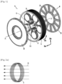
- the electric machine 1 comprises an armature 2 and an inductor 3.
- the machine 1 may be an axial flux or radial flux flux barrier electric machine and may operate in motor mode, in which it is supplied with electricity to provide a driving rotary force, or in generator mode, in which it is rotated to provide electrical energy.
- the electric machine 1 is an axial flux electric machine, and operates in generator mode.
- the armature 2 is formed by the stator of the electric machine and the rotating part of the inductor 3 forms the rotor of the electric machine.
- such a flux barrier superconducting electric machine operates as follows.
- the electromagnetic coils of the coil arrangement are exposed to this changing magnetic field B created by the rotation of the rotor. An electromotive force is then generated.
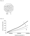
- the coils of the armature coil arrangement are made from a multifilament conductor comprising, for example, several filaments in a resistive matrix suitable for reducing eddy currents.
- the number of filaments may vary between 20 and 100, the resistive matrix being, for example, made of titanium.
- the filaments are made of twisted MgB2.
- the machine according to the invention comprising a superconducting inductor and armature, allows a reduction of the air gap.
- the inductor and the armature can be placed in a common cryogenic enclosure equipped with cooling means specific to each of the superconducting elements.
- the electrical machine 1 comprises a single stator S and two rotors R placed on either side of the stator.
- a single stator S and two rotors R placed on either side of the stator.
- an arrangement with two stators and one stator could also be provided.
- This enclosure is equipped with cooling means specific to each superconducting element of the electrical machine, which are intended to keep the temperature of each of these elements below their critical temperature.
- These cooling means are in particular intended to simultaneously cool the superconducting elements of the machine so as to cool them to a temperature below the lowest critical temperature of these elements.
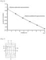
- the cooling is obtained by placing the cryogenic enclosure 11 under vacuum in order to prevent any transfer of heat by convection between the rotor, the armature and the induction coil 6.
- means for limiting these exchanges can be provided, for example by making these elements black in color.
- means for cooling each element by conduction may be provided, for example by contact with a cold solid element.
- a cryogenic fluid may be injected into the cryogenic enclosure 11 to directly cool the various elements placed in the enclosure by convection.
- a helium-based cryogen could be used.
- a sealing gasket 14 is provided in order to prevent cryogen leaks.
- the common cooling means ensure the cooling of all of these elements to the same temperature below the lowest critical temperature.
- the machine comprises two cryogenic cooling enclosures 15 and 16 inside which are respectively placed the superconducting induction coil 6, on the one hand, and the rotors and the stator, on the other hand.
- each enclosure is associated with cooling means specific to the superconducting elements it contains in order to cool these elements specifically to a temperature below their critical temperature.
- These cooling means may consist either of placing the enclosure under vacuum, combined where appropriate with means for reducing the emissivity of the materials and with cooling means by conduction, or consist of injecting a cryogen into each enclosure in order to cool the elements directly. It is advantageous to provide that at least the rotor(s) are placed in a cooling enclosure under vacuum, making it possible to reduce friction losses.
- sealing means can also be provided to limit cryogen leaks.
- each enclosure is equipped with means of cooling by vacuum combined, where appropriate, with means for reducing the emissivity of the materials and means of cooling by conduction or by injection of a cryogen for cooling the superconducting elements by convection.
- sealing means may be provided for each cryogenic enclosure.
Landscapes
- Engineering & Computer Science (AREA)
- Power Engineering (AREA)
- Chemical & Material Sciences (AREA)
- Combustion & Propulsion (AREA)
- Mechanical Engineering (AREA)
- Aviation & Aerospace Engineering (AREA)
- Superconductive Dynamoelectric Machines (AREA)
Claims (9)
- Supraleitende elektrische Maschine mit Flussbarriere, umfassend einen induziertes Element (2) und einen Induktor (3), wobei der Induktor (3) eine supraleitende Induktionsspule (6) und einen rotierenden Teil, der einen Rotor (R) bildet, umfasst, und der induziertes Element eine Anordnung (4) von elektromagnetischen Spulen (5) koaxial zur supraleitenden Induktionsspule (6) umfasst, wobei der Rotor (R) supraleitende Kügelchen (7) umfasst, die radial innerhalb der supraleitenden Spule (6) auf einer Drehachse der Maschine montiert sind, wobei die supraleitenden Kügelchen (7) in orthoradialer Richtung der elektrischen Maschine verteilt und so eingerichtet sind, dass sie Flussbarrieren bilden, dadurch gekennzeichnet, dass die elektromagnetischen Spulen (5) aus supraleitendem Material hergestellt sind und dass der induziertes Element (2) und der Induktor (3) in einer eine Kühlkammer (11; 15, 16; 17, 18, 19, 20) bildenden Baugruppe angeordnet sind, die mit Kühlmitteln ausgestattet ist, die für jedes der supraleitenden Elemente des induziertes Element (2) und des Induktors (3) spezifisch sind, wobei die elektromagnetischen Spulen (5) verdrillte Filamente umfassen, die MgB2 in einer Titanmatrix umfassen.
- Maschine nach Anspruch 1, die ferner ein Statorjoch (8) mit mindestens einer Eisenkrone umfasst.
- Maschine nach einem der Ansprüche 1 und 2, wobei das induzierte Element (2) und der Induktor (3) in einer gemeinsamen Kryokühlkammer angeordnet sind.
- Maschine nach einem der Ansprüche 1 und 2, wobei die eine Kühlkammer bildende Baugruppe eine erste Kryokammer (15), in der die supraleitende Induktionsspule (6) platziert ist, und eine zweite Kryokammer (16) umfasst, in der der mindestens eine Induktor (3) und der mindestens ein induziertes Element (2) platziert sind.
- Maschine nach einem der Ansprüche 1 und 2, wobei die eine Kühlkammer bildende Baugruppe eine erste Kryokammer (17), in der die supraleitende Spule (6) platziert ist, und Kryokammern (18, 19, 20) umfasst, in denen jeweils der mindestens eine Induktor (3) und der mindestens ein induziertes Element (2) platziert sind.
- Maschine nach einem der Ansprüche 1 bis 5, wobei die eine Kühlkammer bildende Baugruppe mindestens eine Vakuumkammer umfasst.
- Maschine nach Anspruch 6, die ferner leitfähige Kühlmittel umfasst.
- Maschine nach einem der Ansprüche 1 bis 7, wobei die eine Kühlkammer bildende Baugruppe mit einem Kryogen gefüllt ist.
- Luftfahrzeug, das mindestens eine Turbomaschine umfasst, die eine elektrische Maschine nach einem der Ansprüche 1 bis 8 umfasst.
Applications Claiming Priority (2)
| Application Number | Priority Date | Filing Date | Title |
|---|---|---|---|
| FR1913738A FR3104341A1 (fr) | 2019-12-04 | 2019-12-04 | Machine électrique à barrière de flux à induit et inducteur supraconducteurs |
| PCT/EP2020/084003 WO2021110618A1 (fr) | 2019-12-04 | 2020-12-01 | Machine électrique à barrière de flux à induit et inducteur supraconducteurs |
Publications (2)
| Publication Number | Publication Date |
|---|---|
| EP4070442A1 EP4070442A1 (de) | 2022-10-12 |
| EP4070442B1 true EP4070442B1 (de) | 2025-07-09 |
Family
ID=69743445
Family Applications (1)
| Application Number | Title | Priority Date | Filing Date |
|---|---|---|---|
| EP20812081.6A Active EP4070442B1 (de) | 2019-12-04 | 2020-12-01 | Elektrische fluxgate-maschine mit supraleitende erreger- und ankerwicklung |
Country Status (4)
| Country | Link |
|---|---|
| US (1) | US20230006534A1 (de) |
| EP (1) | EP4070442B1 (de) |
| FR (1) | FR3104341A1 (de) |
| WO (1) | WO2021110618A1 (de) |
Families Citing this family (1)
| Publication number | Priority date | Publication date | Assignee | Title |
|---|---|---|---|---|
| FR3132591B1 (fr) * | 2022-02-08 | 2024-03-22 | Safran | Protection des bobines d’une machine électrique |
Family Cites Families (13)
| Publication number | Priority date | Publication date | Assignee | Title |
|---|---|---|---|---|
| US3564307A (en) * | 1968-07-24 | 1971-02-16 | Hitachi Ltd | Rotary electric ac generator utilizing the magnetic shielding and trapping by superconducting plates |
| JPS5142285B1 (de) * | 1969-10-09 | 1976-11-15 | ||
| AU521991B2 (en) * | 1978-03-28 | 1982-05-13 | P. E. Schur | Superconducting ac generator |
| US20070052304A1 (en) * | 2005-09-07 | 2007-03-08 | Philippe Masson | Multi-pattern high temperature superconducting motor using flux trapping and concentration |
| US7786645B2 (en) * | 2006-09-07 | 2010-08-31 | American Superconductor Corporation | Superconducting machine stator |
| US8260387B2 (en) * | 2009-01-09 | 2012-09-04 | Superpower, Inc. | Superconducting articles and methods of fabrication thereof with reduced AC magnetic field losses |
| DE102009010112B3 (de) * | 2009-02-21 | 2010-09-02 | Bruker Eas Gmbh | Verfahren zur supraleitenden Verbindung von MgB2-Supraleiterdrähten über eine MgB2-Matrix aus einem Mg-infiltrierten Borpulver-Presskörper |
| JP5190093B2 (ja) * | 2010-07-26 | 2013-04-24 | 株式会社日立製作所 | 超電導コイルおよびそれを用いた超電導回転機 |
| DK178456B1 (en) * | 2014-08-28 | 2016-03-14 | Envision Energy Denmark Aps | Synchronous superconductive rotary machine having a slidable pole assembly and methods thereof |
| US10270311B2 (en) * | 2015-03-18 | 2019-04-23 | Kato Engineering Inc. | Superconducting electrical machine with two part rotor with center shaft capable of handling bending loads |
| CN105063394B (zh) * | 2015-08-06 | 2017-05-31 | 王海英 | 一种钛或钛合金材料的制备方法 |
| DE102015215130A1 (de) * | 2015-08-07 | 2017-02-09 | Siemens Aktiengesellschaft | Antriebssystem und Verfahren zum Antreiben eines Vortriebsmittels eines Fahrzeugs |
| CN108869543B (zh) * | 2018-06-08 | 2019-10-29 | 中国科学院电工研究所 | 一种飞轮储能用混合式超导磁轴承 |
-
2019
- 2019-12-04 FR FR1913738A patent/FR3104341A1/fr active Pending
-
2020
- 2020-12-01 EP EP20812081.6A patent/EP4070442B1/de active Active
- 2020-12-01 US US17/782,518 patent/US20230006534A1/en active Pending
- 2020-12-01 WO PCT/EP2020/084003 patent/WO2021110618A1/fr not_active Ceased
Also Published As
| Publication number | Publication date |
|---|---|
| WO2021110618A1 (fr) | 2021-06-10 |
| US20230006534A1 (en) | 2023-01-05 |
| FR3104341A1 (fr) | 2021-06-11 |
| EP4070442A1 (de) | 2022-10-12 |
Similar Documents
| Publication | Publication Date | Title |
|---|---|---|
| EP1499001B1 (de) | Kühlvorrichtung für eine elektrische Maschine insbesondere für eine Synchronmaschine mit Dauermagneten | |
| EP2097965B1 (de) | Umspritzte oder abgedichtete elektromaschine | |
| EP4118737B1 (de) | Rotierende elektrische maschine mit supraleitenden elementen und kryogenen umhüllungen | |
| US7049724B2 (en) | Superconducting rotating machines with stationary field coils and axial airgap flux | |
| FR3073683B1 (fr) | Rotor refroidi par canal de refroidissement, machine electrique d'une turbomachine comprenant un tel rotor. | |
| EP4070442B1 (de) | Elektrische fluxgate-maschine mit supraleitende erreger- und ankerwicklung | |
| FR2514965A1 (fr) | Machine electrique synchrone a inducteur supraconducteur | |
| FR3103649A1 (fr) | Stator de machine électrique tournante avec bobinage asymétrique | |
| FR3093599A1 (fr) | Machine électrique supraconductrice et procédé de magnétisation des pastilles supraconductrices | |
| WO2015193562A1 (fr) | Moteur synchrone électromagnétique à flux magnétiques combinés axial et radial | |
| US20040239201A1 (en) | Methods and apparatus for assembling homopolar inductor alternators including superconducting windings | |
| WO2001047093A1 (fr) | Ralentisseur a courants de foucault | |
| FR3100399A1 (fr) | Machine à bobinage toroïdal | |
| FR2710466A1 (fr) | Rotor de machine synchrone. | |
| WO2011113887A2 (fr) | Moteur électrique à aimants permanents comportant un stator fractionné | |
| WO2020174158A1 (fr) | Bobine de machine electrique a refroidissement ameliore | |
| FR3008539A1 (fr) | Actionneur electromagnetique polyentrefers a aimants permanents et elements de bobinage sans fer | |
| WO2014122374A1 (fr) | Moteur ou génératrice électromagnétique polyentrefers à aimants permanents et élément à bobinage sans fer | |
| WO2022074340A1 (fr) | Machine électrique tournante sans aimant et sans balai | |
| FR3071369A1 (fr) | Machine electrique comprenant un stator muni d'un manchon tubulaire interne | |
| WO2022096283A1 (fr) | Rotor de machine electrique avec masque d'obturation dans une barriere de flux | |
| FR3131126A1 (fr) | Machine électrique à écrans magnétiques supraconducteurs | |
| WO2023105147A1 (fr) | Procédé de désexcitation d'une machine électrique supraconductrice par injection de courant | |
| EP4422042B1 (de) | Supraleitender motor mit kühlsystem | |
| WO2023105160A1 (fr) | Machine électrique à soupape de désexcitation |
Legal Events
| Date | Code | Title | Description |
|---|---|---|---|
| STAA | Information on the status of an ep patent application or granted ep patent |
Free format text: STATUS: UNKNOWN |
|
| STAA | Information on the status of an ep patent application or granted ep patent |
Free format text: STATUS: THE INTERNATIONAL PUBLICATION HAS BEEN MADE |
|
| PUAI | Public reference made under article 153(3) epc to a published international application that has entered the european phase |
Free format text: ORIGINAL CODE: 0009012 |
|
| STAA | Information on the status of an ep patent application or granted ep patent |
Free format text: STATUS: REQUEST FOR EXAMINATION WAS MADE |
|
| 17P | Request for examination filed |
Effective date: 20220620 |
|
| AK | Designated contracting states |
Kind code of ref document: A1 Designated state(s): AL AT BE BG CH CY CZ DE DK EE ES FI FR GB GR HR HU IE IS IT LI LT LU LV MC MK MT NL NO PL PT RO RS SE SI SK SM TR |
|
| DAV | Request for validation of the european patent (deleted) | ||
| DAX | Request for extension of the european patent (deleted) | ||
| STAA | Information on the status of an ep patent application or granted ep patent |
Free format text: STATUS: EXAMINATION IS IN PROGRESS |
|
| 17Q | First examination report despatched |
Effective date: 20240508 |
|
| GRAP | Despatch of communication of intention to grant a patent |
Free format text: ORIGINAL CODE: EPIDOSNIGR1 |
|
| STAA | Information on the status of an ep patent application or granted ep patent |
Free format text: STATUS: GRANT OF PATENT IS INTENDED |
|
| INTG | Intention to grant announced |
Effective date: 20250304 |
|
| GRAS | Grant fee paid |
Free format text: ORIGINAL CODE: EPIDOSNIGR3 |
|
| GRAA | (expected) grant |
Free format text: ORIGINAL CODE: 0009210 |
|
| STAA | Information on the status of an ep patent application or granted ep patent |
Free format text: STATUS: THE PATENT HAS BEEN GRANTED |
|
| AK | Designated contracting states |
Kind code of ref document: B1 Designated state(s): AL AT BE BG CH CY CZ DE DK EE ES FI FR GB GR HR HU IE IS IT LI LT LU LV MC MK MT NL NO PL PT RO RS SE SI SK SM TR |
|
| REG | Reference to a national code |
Ref country code: GB Ref legal event code: FG4D Free format text: NOT ENGLISH |
|
| REG | Reference to a national code |
Ref country code: CH Ref legal event code: EP |
|
| REG | Reference to a national code |
Ref country code: IE Ref legal event code: FG4D Free format text: LANGUAGE OF EP DOCUMENT: FRENCH |
|
| REG | Reference to a national code |
Ref country code: DE Ref legal event code: R096 Ref document number: 602020054286 Country of ref document: DE |
|
| REG | Reference to a national code |
Ref country code: NL Ref legal event code: MP Effective date: 20250709 |
|
| PG25 | Lapsed in a contracting state [announced via postgrant information from national office to epo] |
Ref country code: PT Free format text: LAPSE BECAUSE OF FAILURE TO SUBMIT A TRANSLATION OF THE DESCRIPTION OR TO PAY THE FEE WITHIN THE PRESCRIBED TIME-LIMIT Effective date: 20251110 |
|
| PG25 | Lapsed in a contracting state [announced via postgrant information from national office to epo] |
Ref country code: NL Free format text: LAPSE BECAUSE OF FAILURE TO SUBMIT A TRANSLATION OF THE DESCRIPTION OR TO PAY THE FEE WITHIN THE PRESCRIBED TIME-LIMIT Effective date: 20250709 |
|
| REG | Reference to a national code |
Ref country code: AT Ref legal event code: MK05 Ref document number: 1812828 Country of ref document: AT Kind code of ref document: T Effective date: 20250709 |
|
| PG25 | Lapsed in a contracting state [announced via postgrant information from national office to epo] |
Ref country code: IS Free format text: LAPSE BECAUSE OF FAILURE TO SUBMIT A TRANSLATION OF THE DESCRIPTION OR TO PAY THE FEE WITHIN THE PRESCRIBED TIME-LIMIT Effective date: 20251109 |
|
| PGFP | Annual fee paid to national office [announced via postgrant information from national office to epo] |
Ref country code: GB Payment date: 20251229 Year of fee payment: 6 |
|
| PG25 | Lapsed in a contracting state [announced via postgrant information from national office to epo] |
Ref country code: NO Free format text: LAPSE BECAUSE OF FAILURE TO SUBMIT A TRANSLATION OF THE DESCRIPTION OR TO PAY THE FEE WITHIN THE PRESCRIBED TIME-LIMIT Effective date: 20251009 |
|
| REG | Reference to a national code |
Ref country code: LT Ref legal event code: MG9D |
|
| PG25 | Lapsed in a contracting state [announced via postgrant information from national office to epo] |
Ref country code: AT Free format text: LAPSE BECAUSE OF FAILURE TO SUBMIT A TRANSLATION OF THE DESCRIPTION OR TO PAY THE FEE WITHIN THE PRESCRIBED TIME-LIMIT Effective date: 20250709 |
|
| PG25 | Lapsed in a contracting state [announced via postgrant information from national office to epo] |
Ref country code: FI Free format text: LAPSE BECAUSE OF FAILURE TO SUBMIT A TRANSLATION OF THE DESCRIPTION OR TO PAY THE FEE WITHIN THE PRESCRIBED TIME-LIMIT Effective date: 20250709 |
|
| PG25 | Lapsed in a contracting state [announced via postgrant information from national office to epo] |
Ref country code: HR Free format text: LAPSE BECAUSE OF FAILURE TO SUBMIT A TRANSLATION OF THE DESCRIPTION OR TO PAY THE FEE WITHIN THE PRESCRIBED TIME-LIMIT Effective date: 20250709 |
|
| PGFP | Annual fee paid to national office [announced via postgrant information from national office to epo] |
Ref country code: FR Payment date: 20251222 Year of fee payment: 6 |
|
| PG25 | Lapsed in a contracting state [announced via postgrant information from national office to epo] |
Ref country code: GR Free format text: LAPSE BECAUSE OF FAILURE TO SUBMIT A TRANSLATION OF THE DESCRIPTION OR TO PAY THE FEE WITHIN THE PRESCRIBED TIME-LIMIT Effective date: 20251010 |
|
| PG25 | Lapsed in a contracting state [announced via postgrant information from national office to epo] |
Ref country code: SE Free format text: LAPSE BECAUSE OF FAILURE TO SUBMIT A TRANSLATION OF THE DESCRIPTION OR TO PAY THE FEE WITHIN THE PRESCRIBED TIME-LIMIT Effective date: 20250709 |
|
| PG25 | Lapsed in a contracting state [announced via postgrant information from national office to epo] |
Ref country code: LV Free format text: LAPSE BECAUSE OF FAILURE TO SUBMIT A TRANSLATION OF THE DESCRIPTION OR TO PAY THE FEE WITHIN THE PRESCRIBED TIME-LIMIT Effective date: 20250709 |
|
| PG25 | Lapsed in a contracting state [announced via postgrant information from national office to epo] |
Ref country code: PL Free format text: LAPSE BECAUSE OF FAILURE TO SUBMIT A TRANSLATION OF THE DESCRIPTION OR TO PAY THE FEE WITHIN THE PRESCRIBED TIME-LIMIT Effective date: 20250709 Ref country code: BG Free format text: LAPSE BECAUSE OF FAILURE TO SUBMIT A TRANSLATION OF THE DESCRIPTION OR TO PAY THE FEE WITHIN THE PRESCRIBED TIME-LIMIT Effective date: 20250709 |
|
| PG25 | Lapsed in a contracting state [announced via postgrant information from national office to epo] |
Ref country code: RS Free format text: LAPSE BECAUSE OF FAILURE TO SUBMIT A TRANSLATION OF THE DESCRIPTION OR TO PAY THE FEE WITHIN THE PRESCRIBED TIME-LIMIT Effective date: 20251009 |
|
| PG25 | Lapsed in a contracting state [announced via postgrant information from national office to epo] |
Ref country code: ES Free format text: LAPSE BECAUSE OF FAILURE TO SUBMIT A TRANSLATION OF THE DESCRIPTION OR TO PAY THE FEE WITHIN THE PRESCRIBED TIME-LIMIT Effective date: 20250709 |
|
| PG25 | Lapsed in a contracting state [announced via postgrant information from national office to epo] |
Ref country code: RO Free format text: LAPSE BECAUSE OF FAILURE TO SUBMIT A TRANSLATION OF THE DESCRIPTION OR TO PAY THE FEE WITHIN THE PRESCRIBED TIME-LIMIT Effective date: 20250709 |