EP0331559B1 - Configuration set of an electromagnetic brake and its supplying means - Google Patents
Configuration set of an electromagnetic brake and its supplying means Download PDFInfo
- Publication number
- EP0331559B1 EP0331559B1 EP89400498A EP89400498A EP0331559B1 EP 0331559 B1 EP0331559 B1 EP 0331559B1 EP 89400498 A EP89400498 A EP 89400498A EP 89400498 A EP89400498 A EP 89400498A EP 0331559 B1 EP0331559 B1 EP 0331559B1
- Authority
- EP
- European Patent Office
- Prior art keywords
- rotor
- stator
- retarder
- alternator
- inductor
- Prior art date
- Legal status (The legal status is an assumption and is not a legal conclusion. Google has not performed a legal analysis and makes no representation as to the accuracy of the status listed.)
- Expired - Lifetime
Links
Images

Classifications
-
- H—ELECTRICITY
- H02—GENERATION; CONVERSION OR DISTRIBUTION OF ELECTRIC POWER
- H02K—DYNAMO-ELECTRIC MACHINES
- H02K49/00—Dynamo-electric clutches; Dynamo-electric brakes
- H02K49/02—Dynamo-electric clutches; Dynamo-electric brakes of the asynchronous induction type
- H02K49/04—Dynamo-electric clutches; Dynamo-electric brakes of the asynchronous induction type of the eddy-current hysteresis type
- H02K49/043—Dynamo-electric clutches; Dynamo-electric brakes of the asynchronous induction type of the eddy-current hysteresis type with a radial airgap
-
- B—PERFORMING OPERATIONS; TRANSPORTING
- B60—VEHICLES IN GENERAL
- B60L—PROPULSION OF ELECTRICALLY-PROPELLED VEHICLES; SUPPLYING ELECTRIC POWER FOR AUXILIARY EQUIPMENT OF ELECTRICALLY-PROPELLED VEHICLES; ELECTRODYNAMIC BRAKE SYSTEMS FOR VEHICLES IN GENERAL; MAGNETIC SUSPENSION OR LEVITATION FOR VEHICLES; MONITORING OPERATING VARIABLES OF ELECTRICALLY-PROPELLED VEHICLES; ELECTRIC SAFETY DEVICES FOR ELECTRICALLY-PROPELLED VEHICLES
- B60L7/00—Electrodynamic brake systems for vehicles in general
- B60L7/10—Dynamic electric regenerative braking
-
- Y—GENERAL TAGGING OF NEW TECHNOLOGICAL DEVELOPMENTS; GENERAL TAGGING OF CROSS-SECTIONAL TECHNOLOGIES SPANNING OVER SEVERAL SECTIONS OF THE IPC; TECHNICAL SUBJECTS COVERED BY FORMER USPC CROSS-REFERENCE ART COLLECTIONS [XRACs] AND DIGESTS
- Y02—TECHNOLOGIES OR APPLICATIONS FOR MITIGATION OR ADAPTATION AGAINST CLIMATE CHANGE
- Y02T—CLIMATE CHANGE MITIGATION TECHNOLOGIES RELATED TO TRANSPORTATION
- Y02T10/00—Road transport of goods or passengers
- Y02T10/60—Other road transportation technologies with climate change mitigation effect
- Y02T10/64—Electric machine technologies in electromobility
Definitions
- the invention relates to assemblies constituted by an electromagnetic retarder intended to brake a vehicle transmission shaft and by its electrical supply means, assemblies comprising a stator traversed by the shaft, which is centered in this stator by means of appropriate guidance, and a rotor which can be secured to the shaft so as to present an external cylindrical face close to an internal cylindrical face of the stator with interposition of a thin air gap, the rotor comprising an inductor, with coils of electric wire , capable of generating by its electrical excitation a magnetic field with alternating distribution in an annular ferromagnetic part of the stator constituting the armature and associated with a liquid cooling circuit, and the electrical supply of the coils being ensured using a polyphase alternator, in particular three-phase, whose armature is part of the above rotor and is connected to said coils by means of a rectifier also forming part of said rotor, the stator ring composed by the inductor poles of the alternator surrounding with a small clearance the rotor armature
- the retarder is mounted on a section of the vehicle transmission shaft concerned, relatively distant from the motor: this section is itself mounted between two ball bearings carried by two transverse flanges delimiting the axial ends of the stator, then in the form of a cylindrical box, and it is connected to the rest of the shaft by two constant velocity joints.
- the rotor of the device is then in the form of a solid core attached to said central shaft section and extended radially outwards by the inductor coils, in small numbers (typically six).
- Such a construction does not lend itself to direct cantilever mounting on the output of the vehicle gearbox, mounting according to which the stator is cantilevered on the casing of the box and the rotor. is mounted in cantilever on a shaft end coming out of said box, this rotor being also secured to an element of a cardan coupling allowing it to be connected to the rest of the transmission shaft.
- the present invention aims, above all, to make the retarders of the above kind as they lend themselves to such a cantilever mounting.
- the assemblies of the kind defined above are essentially characterized, according to the invention, in that the flange is integral with one of the two jaws of a cardan coupling forming part of the shaft and housed at inside the sleeve, jaw itself cantilevered on the end of a section, of said shaft, which comes out of the casing of the vehicle gearbox and is supported by this casing by means of bearings, in that the stator is carried by an openwork bell-shaped framework itself mounted in overhang on said casing and in that the number of inductor coils of the retarder and that of the inductor poles of the alternator are both greater than or equal to twelve.
- the assembly indicated makes it possible to place the stator armature of the retarder, to be cooled by liquid, very close to the vehicle engine and in particular to the normal water cooling circuit thereof.
- the invention includes, apart from these main provisions, certain other provisions which are preferably used at the same time and which will be more explicitly discussed below.
- FIG. 1 of this drawing schematically shows the assembly, established in accordance with the invention, of an electromagnetic retarder of a vehicle and its means of electrical excitation.
- Figure 2 shows the same assembly in perspective view, portions cut away.
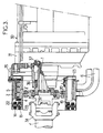
- Figure 3 schematically shows the mounting of such a retarder on the vehicle gearbox.
- the electromagnetic retarder considered is intended to slow down the rotary shaft of a vehicle, preferably of the "heavyweight" type.
- this retarder comprises a rotor 2 secured in rotation with the output shaft 1 of the vehicle gearbox 30 and a stator 3 mounted in cantilever on the casing 31 of this box .
- This annular part 5 is constituted by a cylindrical drum surrounding the inductor with the interposition of a cylindrical air gap E.
- this part 5 is here fixed, it can be easily cooled using a stream of liquid since it is not necessary to have recourse to special seals intended to ensure sealing at the level of connections between two parts in relative movement.
- a liquid circuit 6 is provided for this purpose comprising a section 7 which runs directly along the face of the induced part 5 opposite the air gap E.
- said section 7 is here formed by a pipe extending along a helix around the drum 5, pipe terminated at its two ends by two inlet 8 and outlet 9 fittings.
- Such recesses or reliefs can also be provided on the other walls of said section.
- the circuit section 7 is constituted by a simple annular water jacket delimited by two coaxial cylindrical walls connected to each other on the one hand at their axial ends by two transverse washers and on the other hand by a radial longitudinal partition separating the entrance from the exit.
- the cooling circuit 6 comprises, in addition to the section 7, a drive pump 11 and an external heat exchanger 12, such as a finned radiator, making it possible to dissipate towards the outside the calories carried by the liquid in circulation.
- an external heat exchanger 12 such as a finned radiator
- This liquid is advantageously constituted by water added with anti-freeze.
- the pump 11 and the exchanger 12 are advantageously the water pump and the radiator which form part of the normal cooling circuit of the vehicle engine: it should in fact be noted that, during the operation of the retarder, the engine releases few calories so that its cooling requirements are then reduced; in addition, because the retarder is mounted on the vehicle gearbox 30, it is very close to said normal cooling circuit.
- the axes of the coils 4 which define the inductor poles here extend radially around the axis of the device.
- This inductor being rotary, it is advisable to provide special means for supplying its coils 4 with electric current.
- the multiple poles of the stator are created by a ring of small electromagnets with alternating polarities connected to a source of direct current 15 such as the vehicle battery if the retarder considered equips such a vehicle.
- This circuit 16 advantageously includes a manual control member 17.
- the alternating current collected at the terminals of the rotor 13 is rectified by an appropriate bridge 18 before being applied to the coils 4 of the retarder.
- this armature 13 is secured to the coils 4 of the retarder, all of these elements being mounted on the same sleeve 19 extended internally by a transverse web 20 itself hollowed out by fixing holes 21 and forming a connection flange to a plate 32 secured to the shaft 1.
- This sleeve 19 can form a single piece with cores 4 ′ and with flange 20.
- the plate 32 is in turn secured to one of the two jaws 33 of a cardan coupling, the other jaw 34 of which is secured to the main section 1 ′ of the transmission shaft: as visible in FIG. 3, these two jaws 33 and 34 are freely housed inside the tube formed by the sleeve 19.
- the stator 14 is, for its part, mounted inside a fixed sleeve 22 delimiting the outside of the pipe section 7 above: it is this sleeve 22 which is mounted in cantilever on the casing 31 of the box 30 using an openwork bell frame 35 such as an arm crown.
- the output shaft 1 of the box is rigorously centered in the latter, in particular by means of bearings 36, 37, so that the rotor 2 and the stator 3 are mutually centered and so that the annular air gaps E and e above.
- the number of inductor coils 4 and that of the poles 14 of the generator are relatively high, namely at least equal to twelve, to allow clearing inside the machine of a large diameter space for the passage of the shaft 1 to slow down: in fact, the higher these numbers, the more it is possible to give the corresponding coils and poles small radial lengths; these two numbers are for example here of eighteen and twenty-four respectively.
- this retarder is very easily controlled by simple excitation of the fixed inductor 14 of the generator, excitation which is preferably controlled using the member 17.
Abstract
Description
L'invention est relative aux ensembles constitués par un ralentisseur électromagnétique destiné à freiner un arbre de transmission de véhicule et par ses moyens d'alimentation électrique, ensembles comportant un stator traversé par l'arbre, lequel est centré dans ce stator par des moyens de guidage appropriés, et un rotor solidarisable avec l'arbre de façon à présenter une face cylindrique externe à proximité d'une face cylindrique interne du stator avec interposition d'un entrefer de faible épaisseur, le rotor comportant un inducteur, à bobines de fil électrique, propre à engendrer par son excitation électrique un champ magnétique à répartition alternée dans une pièce ferromagnétique annulaire du stator constituant l'induit et associée à un circuit de refroidissement par liquide, et l'alimentation électrique des bobines étant assurée à l'aide d'un alternateur polyphasé, notamment triphasé, dont l'induit fait partie du rotor ci-dessus et est connecté auxdites bobines par l'intermédiaire d'un redresseur faisant également partie dudit rotor, la couronne statorique composée par les pôles inducteurs de l'alternateur entourant avec un faible jeu l'induit rotorique de cet alternateur et les deux couronnes rotoriques composées respectivement par les bobines inductrices du ralentisseur et par l'induit de l'alternateur étant juxtaposées axialement sur la face extérieure d'un même manchon intérieur de relativement grand diamètre intérieur prolongé intérieurement par une bride de raccordement transversale.The invention relates to assemblies constituted by an electromagnetic retarder intended to brake a vehicle transmission shaft and by its electrical supply means, assemblies comprising a stator traversed by the shaft, which is centered in this stator by means of appropriate guidance, and a rotor which can be secured to the shaft so as to present an external cylindrical face close to an internal cylindrical face of the stator with interposition of a thin air gap, the rotor comprising an inductor, with coils of electric wire , capable of generating by its electrical excitation a magnetic field with alternating distribution in an annular ferromagnetic part of the stator constituting the armature and associated with a liquid cooling circuit, and the electrical supply of the coils being ensured using a polyphase alternator, in particular three-phase, whose armature is part of the above rotor and is connected to said coils by means of a rectifier also forming part of said rotor, the stator ring composed by the inductor poles of the alternator surrounding with a small clearance the rotor armature of this alternator and the two rotor rings composed respectively by the coils inductors of the retarder and by the alternator armature being juxtaposed axially on the outer face of the same inner sleeve of relatively large inner diameter extended internally by a transverse connection flange.
Un tel ensemble a été décrit dans le brevet France n° 1 467 310.Such an assembly has been described in French Patent No. 1,467,310.
Dans cet ensemble, le ralentisseur est monté sur un tronçon, de l'arbre de transmission de véhicule concerné, relativement éloigné du moteur: ce tronçon est lui-même monté entre deux roulements à billes portés par deux flasques transversaux délimitant les extrémités axiales du stator, alors en forme de caisson cylindrique, et il est raccordé au reste de l'arbre par deux joints homocinétiques.In this assembly, the retarder is mounted on a section of the vehicle transmission shaft concerned, relatively distant from the motor: this section is itself mounted between two ball bearings carried by two transverse flanges delimiting the axial ends of the stator, then in the form of a cylindrical box, and it is connected to the rest of the shaft by two constant velocity joints.
Le rotor de l'appareil se présente alors sous la forme d'un noyau massif rapporté sur ledit tronçon d'arbre central et prolongé radialement vers l'extérieur par les bobines inductrices, en petit nombre (typiquement six).The rotor of the device is then in the form of a solid core attached to said central shaft section and extended radially outwards by the inductor coils, in small numbers (typically six).
Une telle construction ne se prête pas à un montage direct en porte-à-faux sur la sortie de la boîte de vitesses du véhicule, montage selon lequel le stator est monté en porte-à-faux sur le carter de la boîte et le rotor est monté en porte-à-faux sur un embout d'arbre sortant de ladite boîte, ce rotor étant par ailleurs solidarisé avec un élément d'un accouplement à cardan permettant de le raccorder au reste de l'arbre de transmission.Such a construction does not lend itself to direct cantilever mounting on the output of the vehicle gearbox, mounting according to which the stator is cantilevered on the casing of the box and the rotor. is mounted in cantilever on a shaft end coming out of said box, this rotor being also secured to an element of a cardan coupling allowing it to be connected to the rest of the transmission shaft.
Or ce montage en porte-à-faux, qui a été décrit dans les brevets France n° 1 456 903 et 1 493 757, est particulièrement précieux vu qu'il rend possible l'utilisation d'un ralentisseur électromagnétique sur une transmission très courte telle que celles équipant les tracteurs de semi-remorques ou les cars à cabine avancée.However, this cantilever mounting, which has been described in French patents Nos. 1,456,903 and 1,493,757, is particularly valuable since it makes it possible to use an electromagnetic retarder on a very short transmission. such as those equipping tractors with semi-trailers or forward cab cars.
La présente invention a pour but, surtout, de rendre les ralentisseurs du genre ci-dessus tels qu'ils se prêtent à un tel montage en porte-à-faux.The present invention aims, above all, to make the retarders of the above kind as they lend themselves to such a cantilever mounting.
A cet effet, les ensembles du genre défini ci-dessus sont essentiellement caractérisés, selon l'invention, en ce que la bride est solidaire de l'une des deux mâchoires d'un accouplement à cardan faisant partie de l'arbre et logé à l'intérieur du manchon, mâchoire elle-même montée en porte-à-faux sur l'extrémité d'un tronçon, dudit arbre, qui sort du carter de la boîte de vitesses du véhicule et est supporté par ce carter par l'intermédiaire de roulements, en ce que le stator est porté par une ossature ajourée en cloche elle-même montée en porte-à-faux sur ledit carter et en ce que le nombre des bobines inductrices du ralentisseur et celui des pôles inducteurs de l'alternateur sont tous deux supérieurs ou égaux à douze.To this end, the assemblies of the kind defined above are essentially characterized, according to the invention, in that the flange is integral with one of the two jaws of a cardan coupling forming part of the shaft and housed at inside the sleeve, jaw itself cantilevered on the end of a section, of said shaft, which comes out of the casing of the vehicle gearbox and is supported by this casing by means of bearings, in that the stator is carried by an openwork bell-shaped framework itself mounted in overhang on said casing and in that the number of inductor coils of the retarder and that of the inductor poles of the alternator are both greater than or equal to twelve.
Le montage indiqué permet de placer l'induit statorique du ralentisseur, à refroidir par liquide, très près du moteur du véhicule et en particulier du circuit normal de refroidissement par eau de celui-ci.The assembly indicated makes it possible to place the stator armature of the retarder, to be cooled by liquid, very close to the vehicle engine and in particular to the normal water cooling circuit thereof.
Dans des modes de réalisation préférés, on a recours en outre à l'une et/ou à l'autre des dispositions suivantes:
- l'extrémité axiale, du rotor du ralentisseur, la plus éloignée du rotor de l'alternateur, est prolongée axialement par une structure ailetée de ventilation du stator lu ralentisseur,
- le nombre des bobines inductrices du ralentisseur est égal à 18 et le nombre des pôles inducteurs de l'alternateur, à 24.
- the axial end of the retarder rotor, furthest from the alternator rotor, is extended axially by a finned structure for ventilating the stator read as retarder,
- the number of inductor coils of the retarder is 18 and the number of inductor poles of the alternator is 24.
L'invention comprend, mises à part ces dispositions principales, certaines autres dispositions qui s'utilisent de préférence en même temps et dont il sera plus explicitement question ci-après.The invention includes, apart from these main provisions, certain other provisions which are preferably used at the same time and which will be more explicitly discussed below.
Dans ce qui suit, l'on va décrire un mode de réalisation de l'invention en se référant au dessin ci-annexé d'une manière bien entendu non limitative.In the following, an embodiment of the invention will be described with reference to the drawing appended hereto of course in a nonlimiting manner.
La figure 1, de ce dessin, montre schématiquement l'ensemble, établi conformément à l'invention, d'un ralentisseur électromagnétique de véhicule et de ses moyens d'excitation électrique.FIG. 1 of this drawing schematically shows the assembly, established in accordance with the invention, of an electromagnetic retarder of a vehicle and its means of electrical excitation.
La figure 2 montre le même ensemble en vue perspective, portions arrachées.Figure 2 shows the same assembly in perspective view, portions cut away.
La figure 3 montre schématiquement le montage d'un tel ralentisseur sur la boîte de vitesses du véhicule.Figure 3 schematically shows the mounting of such a retarder on the vehicle gearbox.
Le ralentisseur électromagnétique considéré est destiné à ralentir l'arbre rotatif d'un véhicule, de préférence du type "poids lourd".The electromagnetic retarder considered is intended to slow down the rotary shaft of a vehicle, preferably of the "heavyweight" type.
D'une façon connue en soi, ce ralentisseur comprend un rotor 2 solidarisé en rotation avec l'arbre de sortie 1 de la boîte de vitesses 30 du véhicule et un stator 3 monté en porte-à-faux sur le carter 31 de cette boîte.In a manner known per se, this retarder comprises a
Mais contrairement à ce qui est habituellement envisagé, c'est ici l'inducteur qui est monté rotatif, l'induit étant fixe.But contrary to what is usually envisaged, it is here the inductor which is rotatably mounted, the armature being fixed.
En d'autres termes:
- les enroulements ou bobines de fil électrique 4 qui conduisent le courant électrique d'excitation du ralentisseur et qui, avec des noyaux radiaux 4′ qu'ils entourent, définissent une couronne de pôles inducteurs à polarités alternées de proche en proche, font partie du
rotor 2, - et la pièce annulaire 5 en matériau ferromagnétique qui constitue l'induit et dans laquelle sont engendrés les courants de Foucault générateurs de freinage et d'échauffement fait partie du
stator 3.
- the windings or coils of electric wire 4 which conduct the electric excitation current of the retarder and which, with radial cores 4 ′ which they surround, define a ring of inducting poles with alternating polarities gradually, are part of the
rotor 2, - and the
annular part 5 made of ferromagnetic material which constitutes the armature and in which the eddy currents which generate braking and heating are generated forms part of thestator 3.
Cette pièce annulaire 5 est constituée par un tambour cylindrique entourant l'inducteur avec interposition d'un entrefer cylindrique E.This
Comme cette pièce 5 est ici fixe, elle peut être facilement refroidie à l'aide d'un courant de liquide puisqu'il n'est pas nécessaire d'avoir recours à des joints spéciaux destinés à assurer l'étanchéité au niveau de raccords entre deux pièces en mouvement relatif.As this
On prévoit à cet effet un circuit de liquide 6 comportant un tronçon 7 qui longe directement la face, de la pièce induite 5, opposée à l'entrefer E.A
Plus précisément ledit tronçon 7 est ici formé par une canalisation s'étendant selon une hélice autour du tambour 5, canalisation terminée à ses deux extrémités par deux raccords d'entrée 8 et de sortie 9.More precisely, said section 7 is here formed by a pipe extending along a helix around the
Pour améliorer l'échange thermique entre le tambour 5 et le liquide circulant dans la canalisation 7, on peut prévoir sur la face, du tambour, délimitant une paroi dudit tronçon, des creux ou reliefs tels que des stries annulaires ou hélicoïdales 10.To improve the heat exchange between the
De tels creux ou reliefs peuvent également être prévus sur les autres parois dudit tronçon.Such recesses or reliefs can also be provided on the other walls of said section.
Selon une variante, le tronçon de circuit 7 est constitué par une simple chemise d'eau annulaire délimitée par deux parois cylindriques coaxiales raccordées entre elles d'une part à leurs extrémités axiales par deux rondelles transversales et d'autre part par une cloison longitudinale radiale séparant l'entrée de la sortie.According to a variant, the circuit section 7 is constituted by a simple annular water jacket delimited by two coaxial cylindrical walls connected to each other on the one hand at their axial ends by two transverse washers and on the other hand by a radial longitudinal partition separating the entrance from the exit.
Le circuit de refroidissement 6 comprend, en plus du tronçon 7, une pompe d'entraînement 11 et un échangeur thermique extérieur 12, tel qu'un radiateur à ailettes, permettant de dissiper vers l'extérieur les calories portées par le liquide en circulation.The
Ce liquide est avantageusement constitué par de l'eau additionnée d'anti-gel.This liquid is advantageously constituted by water added with anti-freeze.
La pompe 11 et l'échangeur 12 sont avantageusement la pompe à eau et le radiateur qui font partie du circuit normal de refroidissement du moteur du véhicule: il est à noter en effet que, lors du fonctionnement du ralentisseur, le moteur dégage peu de calories de sorte que ses besoins de refroidissement sont alors réduits; de plus, du fait que le ralentisseur est monté sur la boîte de vitesses 30 du véhicule, il se trouve très proche dudit circuit normal de refroidissement.The
Les axes des bobines 4 qui définissent les pôles inducteurs s'étendent ici radialement autour de l'axe de l'appareil.The axes of the coils 4 which define the inductor poles here extend radially around the axis of the device.
Cet inducteur étant rotatif, il convient de prévoir des moyens spéciaux pour alimenter ses bobines 4 en courant électrique.This inductor being rotary, it is advisable to provide special means for supplying its coils 4 with electric current.
On a recours à cet effet à une machine tournante génératrice d'électricité dont le rotor est solidarisé avec celui 2 du ralentisseur.This is done using a rotating machine that generates electricity, the rotor of which is secured to that of the
En effet, lorsqu'il existe un besoin de ralentir l'arbre 1, celui-ci tourne: à cette rotation de l'arbre 1 correspond une énergie inutilisée et l'on transforme ici une portion de cette énergie en le courant électrique nécessaire pour alimenter l'inducteur du ralentisseur.Indeed, when there is a need to slow down the shaft 1, it rotates: to this rotation of the shaft 1 corresponds an unused energy and here we transform a portion of this energy into the electric current necessary for supply the retarder inductor.
On obtient de ce fait à la fois les deux avantages suivants:
- on alimente l'inducteur du ralentisseur moyennant un apport d'énergie électrique extérieur très faible, cette énergie étant limitée à celle nécessaire à l'alimentation de l'excitatrice de la génératrice: dans le cas préféré d'un ralentisseur de véhicule, l'énergie d'excitation prélevée sur la batterie de ce véhicule est de l'ordre de 30 % seulement de celle nécessitée par l'alimentation du ralentisseur dans les réalisation habituelles et peut même être nettement plus faible,
- la génération du courant électrique d'alimentation de l'inducteur du ralentisseur consomme par elle-même une certaine énergie mécanique qui est prélevée sur l'arbre à ralentir: cette consommation contribue par elle-même à freiner ledit arbre.
- the inductor of the retarder is supplied by means of a very low external electrical energy supply, this energy being limited to that necessary for supplying the exciter of the generator: in the preferred case of a vehicle retarder, the excitation energy taken from the battery of this vehicle is only around 30% of that required by the power supply of the retarder in the usual embodiments and may even be significantly lower,
- the generation of the electric current supplying the inductor of the retarder consumes by itself a certain mechanical energy which is taken from the shaft to be slowed down: this consumption contributes by itself to braking said shaft.
Dans le mode de réalisation préféré illustré, la génératrice est un alternateur comportant:
- un rotor triphasé 13 constituant l'induit de cet alternateur,
- et un stator inducteur 14 à pôles multiples entourant le
rotor 13 avec un faible jeu formant entrefer e.
- a three-
phase rotor 13 constituting the armature of this alternator, - and an
inductor stator 14 with multiple poles surrounding therotor 13 with a small clearance forming an air gap e .
La liaison électromagnétique entre ce rotor 13 et ce stator 14 est effectuée exclusivement à travers cet entrefer e, sans aucun contact mécanique du type à bague et balai.The electromagnetic connection between this
Les pôles multiples du stator sont créés par une couronne de petits électro-aimants à polarités alternées reliés à une source de courant continu 15 telle que la batterie du véhicule si le ralentisseur considéré équipe un tel véhicule.The multiple poles of the stator are created by a ring of small electromagnets with alternating polarities connected to a source of
Cette liaison est effectuée à travers un circuit de réglage 16 permettant de régler à volonté l'intensité du courant d'excitation de l'inducteur 14, et par suite l'intensité du courant électrique engendré par l'alternateur, et en définitive le couple de freinage appliqué sur le rotor du ralentisseur et donc sur l'arbre 1.This connection is made through an
Ce circuit 16 comporte avantageusement un organe de commande manuelle 17.This
Le courant alternatif recueilli aux bornes du rotor 13 est redressé par un pont approprié 18 avant d'être appliqué sur les bobines 4 du ralentisseur.The alternating current collected at the terminals of the
Bien entendu l'ensemble des composants 18 fait partie du rotor 2 au même titre que les bobines 4 et que l'induit 13.Of course, all of the
Comme bien visible sur la figure 2, cet induit 13 est solidarisé avec les bobines 4 du ralentisseur, l'ensemble de ces éléments étant monté sur un même manchon 19 prolongé intérieurement par un voile transversale 20 lui-même évidé par des trous de fixation 21 et formant bride de raccordement à un plateau 32 solidaire de l'arbre 1. Ce manchon 19 peut former une seule pièce avec les noyaux 4′ et avec la bride 20.As clearly visible in FIG. 2, this
Le plateau 32 est à son tour solidaire de l'une des deux mâchoires 33 d'un accouplement à cardan dont l'autre mâchoire 34 est solidaire du tronçon principal 1′ de l'arbre de transmission: comme visible sur la figure 3, ces deux mâchoires 33 et 34 sont logées librement à l'intérieur du tube formé par le manchon 19.The plate 32 is in turn secured to one of the two
Le stator 14 est, quant à lui, monté à l'intérieur d'un manchon fixe 22 délimitant l'extérieur du tronçon de canalisation 7 ci-dessus: c'est ce manchon 22 qui est monté en porte-à-faux sur le carter 31 de la boîte 30 à l'aide d'une ossature ajourée en cloche 35 telle qu'une couronne de bras.The
Bien entendu, l'arbre 1 de sortie de la boîte est rigoureusement centré dans celle-ci, notamment à l'aide de roulements 36, 37, pour que le rotor 2 et le stator 3 soient centrés mutuellement et que soient formés entre eux les entrefers annulaires E et e ci-dessus.Of course, the output shaft 1 of the box is rigorously centered in the latter, in particular by means of
On voit encore sur les figures 2 et 3 une structure ailetée 23 formant ventilateur et rapportée sur l'extrémité axiale, du rotor 2, la plus éloignée de l'induit 13: cette structure permet d'envoyer un courant d'air de refroidissement entre les bobines 4 du ralentisseur, ce qui contribue à l'évacuation des calories engendrées dans le tambour 5.We also see in Figures 2 and 3 a
Le nombre des bobines inductrices 4 et celui des pôles 14 de la génératrice sont relativement élevés, savoir au moins égaux à douze, pour permettre de dégager à l'intérieur de la machine un espace de grand diamètre pour le passage de l'arbre 1 à ralentir: en effet, plus ces nombres sont élevés, plus il est possible de donner aux bobines et pôles correspondants des petites longueurs radiales; ces deux nombres sont par exemple ici respectivement de dix-huit et de vingt-quatre.The number of inductor coils 4 and that of the
En suite de quoi, et quel que soit le mode de réalisation adopté, on dispose finalement d'un ralentisseur électromagnétique dont la constitution résulte suffisamment de ce qui précède.As a result of what, and whatever the mode of adopted embodiment, there is finally an electromagnetic retarder whose constitution results sufficiently from the above.
Le fonctionnement de ce ralentisseur est très facilement commandé par simple excitation de l'inducteur fixe 14 de la génératrice, excitation qui est de préférence commandée à l'aide de l'organe 17.The operation of this retarder is very easily controlled by simple excitation of the fixed
Ledit ralentisseur présente de nombreux avantages par rapport à ceux antérieurement connus, et en particulier les suivants:
- son montage en porte-à-faux sur la boîte 30 permet de l'utiliser même pour des transmissions très courtes,
- le refroidissement de l'induit 5, fixe, du ralentisseur, par un courant de liquide est facile du fait de sa proximité du circuit de refroidissement à eau normal du véhicule et il est extrêmement efficace, ce qui permet d'obtenir un excellent couple de ralentissement en régime de croisière étant donné que ce couple est d'autant plus élevé que la température de l'induit demeure plus basse,
- l'énergie puisée sur la batterie 15 ou autre source de courant continu est relativement faible vu que cette énergie se limite à celle nécessaire à l'alimentation de l'inducteur 14 de la génératrice, l'alimentation des bobines inductrices 4 du ralentisseur étant intégralement engendrée à partir de la rotation de l'arbre 1: dans la pratique, cette énergie prise sur la batterie est généralement inférieure au tiers de celle requise pour les réalisations à induit rotatif,
- l'excitation du ralentisseur est progressive et continue, ce qui se traduit par une variation semblable du couple de freinage exercée par ledit ralentisseur sur l'arbre à freiner.
- its cantilever mounting on the
box 30 allows it to be used even for very short transmissions, - the cooling of the
armature 5, fixed, of the retarder, by a current of liquid is easy because of its proximity to the normal water cooling circuit of the vehicle and it is extremely efficient, which makes it possible to obtain an excellent torque slowing down at cruising speed since this torque is higher the lower the temperature of the armature, - the energy drawn from the
battery 15 or other source of direct current is relatively low since this energy is limited to that necessary for supplying theinductor 14 of the generator, the supply of the inductor coils 4 of the retarder being entirely generated from the rotation of the shaft 1: in practice, this energy taken from the battery is generally less than a third of that required for embodiments with rotary armature, - the excitation of the retarder is progressive and continuous, which results in a similar variation of the braking torque exerted by said retarder on the shaft to be braked.
Comme il va de soi, et comme il résulte d'ailleurs déjà de ce qui précède, l'invention ne se limite nullement à ceux de ses modes d'application et de réalisation qui ont été plus spécialement envisagés; notamment:
- celles où l'alternateur (13, 14) serait d'un type polyphasé autre que triphasé, notamment de type diphasé ou hexaphasé,
- celles où la face interérieure du manchon intérieur (19) ne serait pas cylindrique, étant par exemple évasée vers son extrémité opposée à la boîte (30),
- celles où la face extérieure du manchon extérieure (22) ne serait pas cylindrique, étant par exemple convergente ou divergente vers son extrémité opposée à la boîte (30),
- celles où l'un et/ou l'autre des deux manchons (19 et 22) serait composé de plusieurs éléments rapportés axialement l'un sur l'autre, par exemple par emmanchement mutuel comme visible sur la figure 3.
- those where the alternator (13, 14) would be of a polyphase type other than three-phase, in particular of the two-phase or six-phase type,
- those where the inner face of the inner sleeve (19) is not cylindrical, being for example flared towards its end opposite the box (30),
- those where the outer face of the outer sleeve (22) is not cylindrical, being for example convergent or diverging towards its end opposite to the box (30),
- those where one and / or the other of the two sleeves (19 and 22) would be composed of several elements attached axially to each other, for example by mutual fitting as visible in FIG. 3.
Claims (2)
Priority Applications (1)
| Application Number | Priority Date | Filing Date | Title |
|---|---|---|---|
| AT89400498T ATE64040T1 (en) | 1988-02-25 | 1989-02-22 | ELECTRICAL SPEED REDUCTION KIT AND ITS ELECTRICAL SUPPLY MEANS. |
Applications Claiming Priority (2)
| Application Number | Priority Date | Filing Date | Title |
|---|---|---|---|
| FR8802301A FR2627913B1 (en) | 1988-02-25 | 1988-02-25 | ELECTROMAGNETIC RETARDER, SUPPLY MEANS, AND APPLICATION TO A VEHICLE |
| FR8802301 | 1988-02-25 |
Publications (2)
| Publication Number | Publication Date |
|---|---|
| EP0331559A1 EP0331559A1 (en) | 1989-09-06 |
| EP0331559B1 true EP0331559B1 (en) | 1991-05-29 |
Family
ID=9363619
Family Applications (1)
| Application Number | Title | Priority Date | Filing Date |
|---|---|---|---|
| EP89400498A Expired - Lifetime EP0331559B1 (en) | 1988-02-25 | 1989-02-22 | Configuration set of an electromagnetic brake and its supplying means |
Country Status (10)
| Country | Link |
|---|---|
| US (1) | US4864173A (en) |
| EP (1) | EP0331559B1 (en) |
| JP (1) | JP2796334B2 (en) |
| KR (1) | KR970006072B1 (en) |
| AT (1) | ATE64040T1 (en) |
| CA (1) | CA1304439C (en) |
| DE (1) | DE68900087D1 (en) |
| ES (1) | ES2022755B3 (en) |
| FR (1) | FR2627913B1 (en) |
| PT (1) | PT89816B (en) |
Families Citing this family (59)
| Publication number | Priority date | Publication date | Assignee | Title |
|---|---|---|---|---|
| FR2653075B1 (en) * | 1989-10-17 | 1992-01-24 | Labavia | IMPROVEMENTS IN TRANSMISSIONS OF VEHICLES EQUIPPED WITH ELECTRIC RETARDERS. |
| US5185543A (en) * | 1990-02-27 | 1993-02-09 | Fichtel & Sachs Ag | Motor vehicle drive line torsional vibration damper |
| JPH0415955U (en) * | 1990-05-29 | 1992-02-10 | ||
| FR2667741B1 (en) * | 1990-10-05 | 1993-01-08 | Labavia | IMPROVEMENTS TO DEVICES FOR MEASURING THE BRAKING TORQUES GENERATED BY ELECTROMAGNETIC RETARDERS AND TO DEVICES FOR ADJUSTING SUCH TORQUES. |
| US5138206A (en) * | 1991-06-04 | 1992-08-11 | Megamation Incorporated | Method and apparatus for cooling hot spots in platen of linear motor system |
| US5347188A (en) * | 1992-09-09 | 1994-09-13 | Sunstrand Corporation | Electric machine with enhanced liquid cooling |
| ES2110861B1 (en) * | 1993-01-29 | 1999-04-01 | Frenos Electricos Unidos Sa | INTERLAYER PIECE FOR THE INSTALLATION OF AN ELECTROMAGNETIC SLOWER ON THE REAR BRIDGE OF A VEHICLE AND FACILITIES INCLUDING SUCH A PART. |
| US5465018A (en) * | 1993-03-18 | 1995-11-07 | Boggs, Iii; Paul D. | Shaft mounted eddy current drive |
| US5650679A (en) * | 1993-03-18 | 1997-07-22 | Boggs, Iii; Paul Dewey | Eddy current drive |
| US5627422A (en) * | 1993-03-18 | 1997-05-06 | Paul D. Boggs, III | Shaft mounted eddy current drive |
| US5434461A (en) * | 1993-03-18 | 1995-07-18 | Boggs, Iii; Paul D. | Shaft mounted eddy current drive |
| US6148967A (en) * | 1998-07-10 | 2000-11-21 | Alliedsignal Inc. | Non-contacting and torquer brake mechanism |
| JP2003501998A (en) * | 1999-06-01 | 2003-01-14 | ローベルト ボツシユ ゲゼルシヤフト ミツト ベシユレンクテル ハフツング | Starter generator for an internal combustion engine and method of making the same |
| FR2803134B1 (en) * | 1999-12-22 | 2002-03-08 | Labinal | Eddy current retarder |
| EP1252035B1 (en) * | 2000-02-02 | 2005-07-27 | Pacific Scientific Electro Kinetics Division | Integrated retarder and accessory device |
| FR2805937B1 (en) * | 2000-03-03 | 2002-12-06 | Daniel Drecq | EDGE CURRENT BRAKING DEVICE AND HEAT EXCHANGER FOR EDGE CURRENT BRAKING DEVICE |
| FR2814003A1 (en) * | 2000-09-14 | 2002-03-15 | Labinal | Electrical supply to automobile transmission shaft eddy current brake, in which assembly eliminates the need for liquid cooling system air cooling is sufficient |
| WO2002043229A2 (en) * | 2000-11-27 | 2002-05-30 | Visapa, S.L.U. | Retarder, particularly provided as a braking device or auxiliary braking device for vehicles or the like, especially rail vehicles |
| FR2819351B1 (en) * | 2001-01-09 | 2003-04-11 | Telma | ASSEMBLY CONSISTING OF AN ELECTROMAGNETIC RETARDER AND ITS POWER SUPPLY MEANS |
| US6581731B2 (en) * | 2001-07-13 | 2003-06-24 | Shui-Jung Chen | Autonomous generation brake assembly |
| CA2482853A1 (en) * | 2002-05-02 | 2003-11-13 | Gmp Surgical Solutions, Inc. | Apparatus for positioning a medical instrument |
| FR2842961B1 (en) * | 2002-07-29 | 2006-03-03 | Telma | ELECTROMAGNETIC RETARDER OF A VEHICLE PROVIDED WITH A SPEED MULTIPLIER DEVICE |
| FR2859687A1 (en) * | 2003-06-27 | 2005-03-18 | Telma | DECELERATION DEVICE FOR MOTOR VEHICLE AND USE THEREOF |
| US7137673B2 (en) * | 2003-06-27 | 2006-11-21 | Visteon Global Technologies, Inc. | Vehicle yaw stability system and method |
| FR2858724B1 (en) * | 2003-06-30 | 2006-04-28 | Telma | ELECTROMAGNETIC RETARDER OF A MOTOR VEHICLE |
| FR2859325A1 (en) * | 2003-06-30 | 2005-03-04 | Telma | Water cooled electromagnetic brake for heavy road vehicle such as lorry or bus, includes fluid filled coolant chambers both inside and outside stator assembly |
| FR2860355B1 (en) * | 2003-09-26 | 2005-12-23 | Telma | ELECTROMAGNETIC RETARDER WITH A CLEARANCE AREA |
| FR2861914A1 (en) * | 2003-10-31 | 2005-05-06 | Telma | ELECTROMAGNETIC RETARDER WITH WATER COOLING |
| FR2864370A1 (en) * | 2003-12-19 | 2005-06-24 | Telma | Electromagnetic retarder for use in e.g. bus or truck, has multibody blower with two rotating blowers whose diameters are increased in air flow direction, and whose rotation axes are oriented in axial manner with respect to shaft axis |
| FR2864367B1 (en) * | 2003-12-19 | 2006-10-27 | Telma | VENTILATION DEVICE FOR ROTATING ELECTRIC MACHINE AROUND A TREE, WITH A FAN INDEPENDENT OF THE TREE |
| FR2867914B1 (en) * | 2004-03-18 | 2006-09-15 | Telma | COOLING LINE FOR A ROTATING ELECTRIC MACHINE, AND A ROTATIONAL ELECTRIC MACHINE COMPRISING SUCH A LINE |
| FR2868621A1 (en) * | 2004-03-31 | 2005-10-07 | Telma Sa | Electromagnetic retarder for e.g. bus, has connecting studs installed in cooling chamber walls, and having projecting part extending in chamber to create turbulences in cooling liquid, where studs permit to evacuate heat at stator surface |
| FR2872643A1 (en) * | 2004-06-30 | 2006-01-06 | Valeo Equip Electr Moteur | COOLING SHIRT FOR A ROTARY MACHINE AND ROTATING MACHINE HAVING SUCH A COOLING SHIRT |
| FR2875968B1 (en) * | 2004-09-30 | 2007-12-28 | Telma Sa | WATER-COOLED ELECTROMAGNETIC RETARDER, METHOD OF CONTROLLING A RETARDER AND MOTOR VEHICLE COMPRISING SUCH RETARDER |
| FR2885274B1 (en) * | 2005-04-29 | 2007-07-27 | Telma Sa | DEBRASABLE FAN FOR AN ELECTROMAGNETIC RETARDER |
| FR2894091A1 (en) * | 2005-11-30 | 2007-06-01 | Telma Sa | Radiator`s fan controlling method for e.g. truck, involves controlling switching of fan using switching units based on temperature value of cooling liquid traversing electromagnetic retarder, where represents rate of flow of cooling liquid |
| FR2894411B1 (en) * | 2005-12-07 | 2008-06-13 | Telma Sa | METHOD FOR CONTROLLING AN ELECTROMAGNETIC RETARDER |
| FR2894734B1 (en) * | 2005-12-09 | 2008-03-14 | Telma Sa | METHOD FOR COMMISSIONING AN ELECTROMAGNETIC RETARDER |
| FR2895166B1 (en) * | 2005-12-19 | 2008-06-13 | Telma Sa | METHOD OF DETECTING FAULT OF FURNITURE OF ELECTROMAGNETIC RETARDER |
| FR2895596B1 (en) * | 2005-12-22 | 2008-03-14 | Telma Sa | METHOD FOR CONTROLLING AN ELECTROMAGNETIC RETARDER |
| FR2895595B1 (en) * | 2005-12-22 | 2008-03-14 | Telma Sa | METHOD FOR CONTROLLING AN ELECTROMAGNETIC RETARDER |
| AT505585A3 (en) * | 2006-09-08 | 2015-01-15 | Seiwald Andreas | LIQUID-COOLED SWITCH BRAKE |
| FR2918512B1 (en) * | 2007-05-21 | 2014-03-28 | Valeo Equip Electr Moteur | ROTATING ELECTRIC MACHINE COMPLIANT TO OPERATE AT AT LEAST TWO DIFFERENT ELECTRICAL VOLTAGES |
| DE102009022675A1 (en) * | 2009-05-26 | 2010-12-16 | Horiba Europe Gmbh | Test bench with temperature-controlled cooling fan |
| FR2948243B1 (en) * | 2009-07-17 | 2011-10-07 | Valeo Equip Electr Moteur | CURRENT RECTIFIER BRIDGE FOR A POLYPHASE ALTERNATOR AND A POLYPHASE ALTERNATOR COMPRISING SUCH A BRIDGE |
| IT1398207B1 (en) * | 2010-02-16 | 2013-02-14 | Alenia Aeronautica Spa | BRAKE SYSTEM FOR AIRCRAFT TROLLEY. |
| DE102010051715A1 (en) * | 2010-11-19 | 2012-05-24 | Voith Patent Gmbh | Powertrain with a hydrodynamic retarder |
| CN102299608B (en) * | 2011-07-12 | 2013-10-16 | 北京工业大学 | Liquid cooling auto-excitation-type eddy current retarder without electric brush structure |
| DE102011082353B4 (en) * | 2011-09-08 | 2021-04-01 | Siemens Aktiengesellschaft | Stator for an electric motor |
| FR2984626B1 (en) | 2011-12-20 | 2014-01-17 | Valeo Equip Electr Moteur | HIGH-LEVEL ROTOR HAVING A WINDING ISOLATION DEVICE AND A WINDING INSULATION DEVICE THEREFOR |
| FR2984627B1 (en) | 2011-12-20 | 2016-06-24 | Valeo Equip Electr Moteur | HIGH SPEED ROTOR HAVING A WINDING WIRE GUIDE PIECE, A WINDING WIRE GUIDE PIECE AND AN ASSOCIATED WINDING METHOD |
| US9067500B2 (en) * | 2012-05-21 | 2015-06-30 | Krassimire Mihaylov Penev | Self rechargeable synergy drive for a motor vehicle |
| US8646550B2 (en) | 2012-05-21 | 2014-02-11 | Krassimire Mihaylov Penev | Self rechargeable synergy drive for a motor vehicle |
| US9531242B2 (en) | 2012-12-31 | 2016-12-27 | Teco-Westinghouse Motor Company | Apparatuses and methods for cooling electric machines |
| WO2016024030A1 (en) * | 2014-08-14 | 2016-02-18 | Ralentizadores Y Transformaciones, S.A. | Autonomous retarder system for a vehicle, and vehicle including same |
| CN105790542B (en) * | 2016-03-25 | 2018-09-14 | 武汉理工大学 | A kind of electromagnetic retarder with energy recovery function |
| US11043875B2 (en) * | 2018-11-20 | 2021-06-22 | GM Global Technology Operations LLC | Temperature control assembly for an electric machine |
| US20220069663A1 (en) * | 2019-01-10 | 2022-03-03 | Mitsubishi Heavy Industries Engine & Turbocharger, Ltd. | Motor, and inverter-integrated rotating electric machine |
| WO2023281128A1 (en) * | 2021-07-07 | 2023-01-12 | Ralentizadores Y Transformaciones, S.A. | Power supply system for a retarder of a vehicle, autonomous retarder and method for making a retarder autonomous |
Family Cites Families (9)
| Publication number | Priority date | Publication date | Assignee | Title |
|---|---|---|---|---|
| BE569173A (en) * | 1957-12-17 | |||
| US3184626A (en) * | 1961-01-09 | 1965-05-18 | Emerson Electric Co | Eddy current clutch and power supply therefor |
| US3416016A (en) * | 1965-01-11 | 1968-12-10 | Hitachi Ltd | Speed reduction apparatus for automotive vehicles |
| GB1147373A (en) | 1965-09-16 | 1969-04-02 | Labavia | Improvements in or relating to vehicle transmissions including an eddy current retarder |
| US3889140A (en) * | 1968-08-31 | 1975-06-10 | Max Baermann Fa | Induction brake or clutch |
| US4362958A (en) * | 1980-11-03 | 1982-12-07 | Eaton Corporation | Electromagnetic coupling and cooling system therefor |
| US4570094A (en) * | 1984-01-23 | 1986-02-11 | Sundstrand Corporation | Rotating rectifier assembly |
| FR2591297B1 (en) * | 1985-12-06 | 1990-03-30 | Renault Vehicules Ind | RETARDER CLUTCH. |
| JPH0632503A (en) * | 1992-07-13 | 1994-02-08 | Konica Corp | Noncontact conveying device |
-
1988
- 1988-02-25 FR FR8802301A patent/FR2627913B1/en not_active Expired - Lifetime
-
1989
- 1989-02-17 US US07/311,978 patent/US4864173A/en not_active Expired - Lifetime
- 1989-02-22 DE DE8989400498T patent/DE68900087D1/en not_active Expired - Lifetime
- 1989-02-22 AT AT89400498T patent/ATE64040T1/en not_active IP Right Cessation
- 1989-02-22 ES ES89400498T patent/ES2022755B3/en not_active Expired - Lifetime
- 1989-02-22 EP EP89400498A patent/EP0331559B1/en not_active Expired - Lifetime
- 1989-02-22 CA CA000591747A patent/CA1304439C/en not_active Expired - Lifetime
- 1989-02-23 JP JP1042030A patent/JP2796334B2/en not_active Expired - Fee Related
- 1989-02-23 PT PT89816A patent/PT89816B/en active IP Right Grant
- 1989-02-24 KR KR1019890002218A patent/KR970006072B1/en not_active IP Right Cessation
Also Published As
| Publication number | Publication date |
|---|---|
| FR2627913B1 (en) | 1992-02-07 |
| KR970006072B1 (en) | 1997-04-23 |
| FR2627913A1 (en) | 1989-09-01 |
| CA1304439C (en) | 1992-06-30 |
| EP0331559A1 (en) | 1989-09-06 |
| DE68900087D1 (en) | 1991-07-04 |
| ATE64040T1 (en) | 1991-06-15 |
| US4864173A (en) | 1989-09-05 |
| KR890012823A (en) | 1989-09-19 |
| PT89816B (en) | 1994-02-28 |
| JPH01255468A (en) | 1989-10-12 |
| ES2022755B3 (en) | 1991-12-01 |
| JP2796334B2 (en) | 1998-09-10 |
| PT89816A (en) | 1989-10-04 |
Similar Documents
| Publication | Publication Date | Title |
|---|---|---|
| EP0331559B1 (en) | Configuration set of an electromagnetic brake and its supplying means | |
| EP1499001B1 (en) | Cooling arrangement for electrical machines specially for a permanent magnet syncronous machine | |
| EP1784908A1 (en) | Water jacket for a rotary machine and rotary machine comprising same | |
| WO2019063306A1 (en) | Liquid cooling circuit for a rotary electric machine | |
| FR2910736A1 (en) | Stator for e.g. alternator, of motor vehicle, has body including two complementary annular parts that have axial lengths respectively, and tooth alternatively integrated to one of annular parts of body | |
| EP1878105A1 (en) | Self-disengaging fan for an electromagnetic retarder | |
| FR2489939A1 (en) | Mechanical energy to magnetic water heater - has magnetic rotor inducing heat in stator to heat water | |
| WO2001047093A1 (en) | Foucault current retarder | |
| WO2013136022A2 (en) | Assembly of flanges of the rotor of a rotary electric machine comprising asymmetric openings promoting an axial air flow inside the rotor, and related electric machine rotor | |
| EP1527509A1 (en) | Electromagnetic retarder for a vehicle provided with a speed increasing unit | |
| EP1235332B1 (en) | Unity consisting of an electromagnetic retarder and its electric supply | |
| EP3673566A1 (en) | Electric machine with cooling device comprising a partially subdivided channel | |
| EP3782270B1 (en) | Synchronous electrical machine | |
| FR3071369A1 (en) | ELECTRIC MACHINE COMPRISING A STATOR HAVING AN INTERNAL TUBULAR SLEEVE | |
| FR2814003A1 (en) | Electrical supply to automobile transmission shaft eddy current brake, in which assembly eliminates the need for liquid cooling system air cooling is sufficient | |
| FR2578117A1 (en) | ROTOR FOR ROTARY ELECTRIC MACHINE SUPERCONDUCTING | |
| EP4070442A1 (en) | Flux barrier electric motor with superconducting armature and inductor | |
| EP0244307B1 (en) | Armatures of electromagnetic reducers | |
| FR2820559A1 (en) | ALTERNATOR | |
| FR2859325A1 (en) | Water cooled electromagnetic brake for heavy road vehicle such as lorry or bus, includes fluid filled coolant chambers both inside and outside stator assembly | |
| FR2545663A1 (en) | STARTER MOTOR HOUSING | |
| EP4120513A1 (en) | Electrical machine with cooling of winding heads | |
| WO2008017785A2 (en) | Arrangement for an electronic circuit in a rotating electrical machine and rotating electrical machine comprising said arrangement | |
| EP2634896A2 (en) | Sealed electric motor comprising a heat exchanger | |
| FR3131126A1 (en) | Electrical machine with superconducting magnetic screens |
Legal Events
| Date | Code | Title | Description |
|---|---|---|---|
| PUAI | Public reference made under article 153(3) epc to a published international application that has entered the european phase |
Free format text: ORIGINAL CODE: 0009012 |
|
| AK | Designated contracting states |
Kind code of ref document: A1 Designated state(s): AT BE CH DE ES FR GB IT LI NL SE |
|
| 17P | Request for examination filed |
Effective date: 19891221 |
|
| 17Q | First examination report despatched |
Effective date: 19900419 |
|
| GRAA | (expected) grant |
Free format text: ORIGINAL CODE: 0009210 |
|
| ITF | It: translation for a ep patent filed |
Owner name: UFFICIO TECNICO ING. A. MANNUCCI |
|
| AK | Designated contracting states |
Kind code of ref document: B1 Designated state(s): AT BE CH DE ES FR GB IT LI NL SE |
|
| REF | Corresponds to: |
Ref document number: 64040 Country of ref document: AT Date of ref document: 19910615 Kind code of ref document: T |
|
| GBT | Gb: translation of ep patent filed (gb section 77(6)(a)/1977) | ||
| REF | Corresponds to: |
Ref document number: 68900087 Country of ref document: DE Date of ref document: 19910704 |
|
| PLBE | No opposition filed within time limit |
Free format text: ORIGINAL CODE: 0009261 |
|
| STAA | Information on the status of an ep patent application or granted ep patent |
Free format text: STATUS: NO OPPOSITION FILED WITHIN TIME LIMIT |
|
| 26N | No opposition filed | ||
| EAL | Se: european patent in force in sweden |
Ref document number: 89400498.5 |
|
| REG | Reference to a national code |
Ref country code: FR Ref legal event code: TP |
|
| PGFP | Annual fee paid to national office [announced via postgrant information from national office to epo] |
Ref country code: DE Payment date: 20010201 Year of fee payment: 13 |
|
| REG | Reference to a national code |
Ref country code: CH Ref legal event code: PFA Free format text: LABAVIA S.G.E. TRANSFER- LABINAL |
|
| REG | Reference to a national code |
Ref country code: GB Ref legal event code: IF02 |
|
| PGFP | Annual fee paid to national office [announced via postgrant information from national office to epo] |
Ref country code: AT Payment date: 20020124 Year of fee payment: 14 |
|
| PGFP | Annual fee paid to national office [announced via postgrant information from national office to epo] |
Ref country code: GB Payment date: 20020125 Year of fee payment: 14 |
|
| PGFP | Annual fee paid to national office [announced via postgrant information from national office to epo] |
Ref country code: SE Payment date: 20020128 Year of fee payment: 14 Ref country code: NL Payment date: 20020128 Year of fee payment: 14 Ref country code: BE Payment date: 20020128 Year of fee payment: 14 Ref country code: CH Payment date: 20020128 Year of fee payment: 14 |
|
| PG25 | Lapsed in a contracting state [announced via postgrant information from national office to epo] |
Ref country code: DE Free format text: LAPSE BECAUSE OF NON-PAYMENT OF DUE FEES Effective date: 20020903 |
|
| REG | Reference to a national code |
Ref country code: FR Ref legal event code: TP |
|
| REG | Reference to a national code |
Ref country code: GB Ref legal event code: 732E |
|
| PG25 | Lapsed in a contracting state [announced via postgrant information from national office to epo] |
Ref country code: GB Free format text: LAPSE BECAUSE OF NON-PAYMENT OF DUE FEES Effective date: 20030222 Ref country code: AT Free format text: LAPSE BECAUSE OF NON-PAYMENT OF DUE FEES Effective date: 20030222 |
|
| PG25 | Lapsed in a contracting state [announced via postgrant information from national office to epo] |
Ref country code: SE Free format text: LAPSE BECAUSE OF NON-PAYMENT OF DUE FEES Effective date: 20030223 |
|
| PG25 | Lapsed in a contracting state [announced via postgrant information from national office to epo] |
Ref country code: BE Free format text: LAPSE BECAUSE OF NON-PAYMENT OF DUE FEES Effective date: 20030228 Ref country code: LI Free format text: LAPSE BECAUSE OF NON-PAYMENT OF DUE FEES Effective date: 20030228 Ref country code: CH Free format text: LAPSE BECAUSE OF NON-PAYMENT OF DUE FEES Effective date: 20030228 |
|
| PG25 | Lapsed in a contracting state [announced via postgrant information from national office to epo] |
Ref country code: NL Free format text: LAPSE BECAUSE OF NON-PAYMENT OF DUE FEES Effective date: 20030901 |
|
| EUG | Se: european patent has lapsed | ||
| GBPC | Gb: european patent ceased through non-payment of renewal fee | ||
| REG | Reference to a national code |
Ref country code: CH Ref legal event code: PL |
|
| NLV4 | Nl: lapsed or anulled due to non-payment of the annual fee |
Effective date: 20030901 |
|
| PG25 | Lapsed in a contracting state [announced via postgrant information from national office to epo] |
Ref country code: IT Free format text: LAPSE BECAUSE OF NON-PAYMENT OF DUE FEES;WARNING: LAPSES OF ITALIAN PATENTS WITH EFFECTIVE DATE BEFORE 2007 MAY HAVE OCCURRED AT ANY TIME BEFORE 2007. THE CORRECT EFFECTIVE DATE MAY BE DIFFERENT FROM THE ONE RECORDED. Effective date: 20050222 |
|
| PGFP | Annual fee paid to national office [announced via postgrant information from national office to epo] |
Ref country code: ES Payment date: 20070209 Year of fee payment: 19 |
|
| PGFP | Annual fee paid to national office [announced via postgrant information from national office to epo] |
Ref country code: FR Payment date: 20070227 Year of fee payment: 19 |
|
| REG | Reference to a national code |
Ref country code: FR Ref legal event code: ST Effective date: 20081031 |
|
| PG25 | Lapsed in a contracting state [announced via postgrant information from national office to epo] |
Ref country code: FR Free format text: LAPSE BECAUSE OF NON-PAYMENT OF DUE FEES Effective date: 20080229 |
|
| REG | Reference to a national code |
Ref country code: ES Ref legal event code: FD2A Effective date: 20080223 |
|
| PG25 | Lapsed in a contracting state [announced via postgrant information from national office to epo] |
Ref country code: ES Free format text: LAPSE BECAUSE OF NON-PAYMENT OF DUE FEES Effective date: 20080223 |