EP0331491B1 - Flexibler Behälter für Flüssigkeiten - Google Patents
Flexibler Behälter für Flüssigkeiten Download PDFInfo
- Publication number
- EP0331491B1 EP0331491B1 EP89302089A EP89302089A EP0331491B1 EP 0331491 B1 EP0331491 B1 EP 0331491B1 EP 89302089 A EP89302089 A EP 89302089A EP 89302089 A EP89302089 A EP 89302089A EP 0331491 B1 EP0331491 B1 EP 0331491B1
- Authority
- EP
- European Patent Office
- Prior art keywords
- bag
- end wall
- wall panel
- edges
- roof
- Prior art date
- Legal status (The legal status is an assumption and is not a legal conclusion. Google has not performed a legal analysis and makes no representation as to the accuracy of the status listed.)
- Expired - Lifetime
Links
- 239000007788 liquid Substances 0.000 title description 4
- 239000000463 material Substances 0.000 claims abstract description 8
- 238000000034 method Methods 0.000 claims abstract description 4
- 230000003014 reinforcing effect Effects 0.000 claims description 3
- 210000002105 tongue Anatomy 0.000 description 7
- 230000015572 biosynthetic process Effects 0.000 description 6
- 238000005755 formation reaction Methods 0.000 description 6
- 239000002985 plastic film Substances 0.000 description 2
- 230000002787 reinforcement Effects 0.000 description 2
- 238000004873 anchoring Methods 0.000 description 1
- 239000000470 constituent Substances 0.000 description 1
- 238000010276 construction Methods 0.000 description 1
- 239000004744 fabric Substances 0.000 description 1
Images


Classifications
-
- B—PERFORMING OPERATIONS; TRANSPORTING
- B65—CONVEYING; PACKING; STORING; HANDLING THIN OR FILAMENTARY MATERIAL
- B65D—CONTAINERS FOR STORAGE OR TRANSPORT OF ARTICLES OR MATERIALS, e.g. BAGS, BARRELS, BOTTLES, BOXES, CANS, CARTONS, CRATES, DRUMS, JARS, TANKS, HOPPERS, FORWARDING CONTAINERS; ACCESSORIES, CLOSURES, OR FITTINGS THEREFOR; PACKAGING ELEMENTS; PACKAGES
- B65D90/00—Component parts, details or accessories for large containers
- B65D90/02—Wall construction
- B65D90/04—Linings
- B65D90/046—Flexible liners, e.g. loosely positioned in the container
- B65D90/048—Flexible liners, e.g. loosely positioned in the container comprising bracing straps
-
- B—PERFORMING OPERATIONS; TRANSPORTING
- B65—CONVEYING; PACKING; STORING; HANDLING THIN OR FILAMENTARY MATERIAL
- B65D—CONTAINERS FOR STORAGE OR TRANSPORT OF ARTICLES OR MATERIALS, e.g. BAGS, BARRELS, BOTTLES, BOXES, CANS, CARTONS, CRATES, DRUMS, JARS, TANKS, HOPPERS, FORWARDING CONTAINERS; ACCESSORIES, CLOSURES, OR FITTINGS THEREFOR; PACKAGING ELEMENTS; PACKAGES
- B65D88/00—Large containers
- B65D88/16—Large containers flexible
- B65D88/22—Large containers flexible specially adapted for transport
-
- B—PERFORMING OPERATIONS; TRANSPORTING
- B65—CONVEYING; PACKING; STORING; HANDLING THIN OR FILAMENTARY MATERIAL
- B65D—CONTAINERS FOR STORAGE OR TRANSPORT OF ARTICLES OR MATERIALS, e.g. BAGS, BARRELS, BOTTLES, BOXES, CANS, CARTONS, CRATES, DRUMS, JARS, TANKS, HOPPERS, FORWARDING CONTAINERS; ACCESSORIES, CLOSURES, OR FITTINGS THEREFOR; PACKAGING ELEMENTS; PACKAGES
- B65D2590/00—Component parts, details or accessories for large containers
- B65D2590/02—Wall construction
- B65D2590/04—Linings
- B65D2590/043—Flexible liners
- B65D2590/046—Bladders
Definitions
- This invention relates to a storage bag which is particularly suitable for transportation in a container.
- the bag of the invention will mainly find application in the storage of liquids, but is not limited to such application.
- a bulkhead / pallet is provided with the bulkhead disposed adjacent to and supported by the doors of the container, such bulkhead / pallet serving to prevent the bag from bulging out of the container during filling and discharge operations. It will be appreciated that such a bulkhead / pallet arrangement adds weight to a load, and is also space consuming particularly in relation to an empty storage bag.
- DE-A-3 123 150 discloses a rectangular storage container formed from a tube of flexible material by stitching a seam diametrically across the tube, flattening the seam onto material in the tube so that opposed ear formations project upwardly, and folding these ear formations flat onto the seam. One ear formation is folded back on itself to provide a spout.
- FR-A-2 351 855 discloses a harness to support a non-rigid container against movement, comprising a number of spaced flexible steps, and anchoring straps to hold the harness in fixed relation to a support means.
- the storage bag and the method of forming said bag are defined by the features of the independent claims.
- the storage bag is made of flexible sheet material. It is of generally rectangular configuration, comprising a generally planar base section, opposed generally vertically disposed side wall sections, opposed generally vertically disposed end wall sections, and a generally planar roof section.
- the term "generally vertically wall section” herein is meant to include an upwardly directed slanting wall section.
- the bag will comprise a tubular section defining the base side walls and roof, with rectangular end wall sections being secured to each end of the tubular section.
- the end wall sections will be constituted by two sections which fold towards one another from the side wall sections or alternatively from the roof and base sections.
- the end wall sections will be constituted by two half sections of substantially equal size.
- the end wall sections will be constituent by unequal sections.
- the bag may further include a reinforcing harness comprising a plurality of strap elements whereof the free ends are adapted to be secured to the container, preferably to the floor thereof.
- the reinforcing harness will include two or more longitudinal straps extending over the end sections and the roof of the bag, and one or more transverse straps extending over the side wall sections and the roof of the bag.
- two longitudinal straps will be provided, the straps diverging outwardly at the end panels towards the lower bottom corners of the bag.
- a series of cross-brace straps will preferably be provided to link the outwardly diverging straps together at intervals at one or both end zones thereof.
- a blank of elastomeric or plastic sheet material which may or may not be reinforced with fabric for forming the bag of the invention, as disclosed herein.
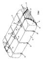
- a liquid storage bag in accordance with the invention is characterised in that it is of generally rectangular configuration comprising a base panel 10, a pair of opposed side panels 11 and 12, a pair of opposed end panels 13 and 14 and a roof panel 15.
- the bag will be formed from a blank 16 which is of rectangular shape. By means of a longitudinal joint 29 this blank is formed into a tubular configuration. Square cutouts 31 are made in the tube to form a pair of tongues 17 at each end as illustrated in Figure 5. The tongues 17 are joined by seams 30 to make the end panel 13 as shown in Figure 6.
- a bag formed as above and depicted in Figure 8 will be of a generally rectangular profile and particularly suitable for housing within a rigid container 19 such as a conventional ISO container. It is envisaged that the bag will be dimensioned to be a snug fit within the container 19.
- the bag shown in Figure 8 will preferably be provided with a harness as described in more detail below and housed within the container 19,
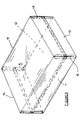
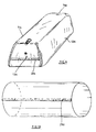
- An alternative arrangement is shown in Figures 9 to 12 which show a version of the bag having side and end walls which slope upwardly in a convergent fashion and which is designed to be free standing within a container 19 without the need for a harness or other supporting devices.
- the bag is of generally trapezoidal profile.
- the bag is formed in a similar manner to the bag shown in Figure 8, by utilizing a blank of rectangular shape, not shown, which is formed into a tubular configuration by means of a longitudinal joint 29a, Figure 10. The difference in construction is found in the cutouts 31a which were not square, but of angled shape as shown in Figure 11.
- tongues 17a are of unequal size.
- the tongues 17a are joined by a seam 30a and the ends folded in the manner shown in Figure 12 to provide angled end seams 18a.
- the seams 18a will be sealed in a conventional manner with additional reinforcement where necessary.
- the bag of Figure 9 is substantially self supporting and when housed within a container will not impinge on the container wall. Accordingly the bag will usually not require constraining means such as a harness or the like.
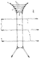
- the harness Figure 3 may be provided for the embodiment of the bag shown in Figures 1, 2 and 8 to control movement thereof, during filling, discharge and transportation. Loops 24 will secure the harness to the bag, Figure 2.
- the harness comprises a pair of longitudinal strap elements 20 and a plurality of transverse strap elements 21.
- the longitudinal strap elements extend from the lower corner zones of the container along one end panel 14 of the bag over the upper surface 15 thereof, and along the other end panel 13 of the bag.
- a suitable hook, clasp of the like formations 22 will be provided for securing the ends of the strap elements to eye formations 26 or the like provided on the floor of the container 19 and adjacent to the walls.
- the longitudinal strap elements 20 are reinforced at least at the door side of the container by means of a plurality of spaced transverse linking straps 23 provided in the zone of the end panel of the bag. It has been found that the longitudinal straps 20 together with these linking straps 23 will limit excessive surge movement of the end preventing the bag from exerting undue stress on or even bulging out of the door of the container.
- linking straps 23 define the contour of the end portions of the strap elements 20. Ring elements serve to link the various strap elements together as shown in Figure 2.
- the transverse straps 21 of the harness extend transversely across the roof 15 of the bag and down each side panel 11 and 12 thereof as illustrated.
- the invention relates to a novel storage bag, a blank for forming such a bag, a harness for use with the bag as well as a transportation system comprising the bag with or without the harness of the invention in combination with a rigid container.
Landscapes
- Engineering & Computer Science (AREA)
- Mechanical Engineering (AREA)
- Tubes (AREA)
- Bag Frames (AREA)
- Packages (AREA)
Claims (10)
- Sammelbehälter aus einem flexiblen Flächenmaterial, geformt aus einem einzelnem Rohling (16), der gegenüberliegende Seitenkanten und gegenüberliegende Stirnkanten hat, der in die Form einer schlauchförmigen Manschette gefaltet ist, der eine Längsnaht (29) hat und entlang derer verbunden ist, die schlauchförmige Manschette definiert eine Grundfläche (10), eine Dachfläche (15) und gegenüberliegende Seitenwände (11, 12) für den Sammelbehälter, dadurch gekennzeichnet, daß die Stirnwände (13, 14) des Sammelbehälters aus Teilstirnwandbahnabschnitten (17) geformt sind, die von den Stirnkanten des gefalteten Rohlings hervorstehen, um von der Dachfläche und Grundfläche oder alternativ dazu von den Seitenwänden wegzuklappen und die entlang einer Naht (30) an deren Stirnkanten verbunden sind, die Seitenkanten der Teilstirnwandbahnabschnitte werden dort an die Seitenwände befestigt, wo die Teilstirnwandbahnabschnitte von der Dach- und Grundfläche des Behälters wegklappen oder alternativ dazu dort an die Dach- und Grundfläche des Behälters befestigt werden, wo die Teilstirnwandbahnabschnitte von den gegenüberliegenden Seitenwänden des Behälters wegklappen.
- Behälter nach Anspruch 1, wobei der Behälter im wesentlichen von rechteckiger Form ist und die Teilstirnwandbahnabschnitte (17) im wesentlichen rechteckig und gleichartig sind.
- Behälter nach Anspruch 1, wobei der Behälter im wesentlichen von trapezähnlicher Form ist und die Teilstirnwandbahnabschnitte (17a) zueinander gefaltet sind, um einen abgestumpften, dreiecksförmigen Stirnwandabschnitt (13a) zu bilden.
- Behälter nach jntedem der Ansprüche 1 bis 3, der ein verstärkendes Gurtwerk enthält, das freie Enden (22) hat, die verwendet werden, um an das Innere der Containers (19) befestigt zu werden, das Gurtwerk enthält zwei oder mehr Längsgurte (20), die sich über die Stirnabschnitte (13, 14) und über die Dachfläche (15) des Behälters erstrecken und enthält einen oder mehrere Quergurte (21), die sich über die Seitenwandabschnitte (11, 12) und über die Dachfläche des Behälters erstrecken.
- Behälter nach Anspruch 4, wobei das Gurtwerk zwei Längsgurte (20) umfaßt, die an den Stirnbahnen (13, 14) des Behälters nach außen in Richtung der unteren Bodenecken des Behälters auseinanderlaufen, mit einer Reihe von Querhaltegurten (23), die zur Verfügung gestellt werden, um die nach außen auseinanderlaufenden Gurte in Abständen an einem oder beiden Endbereichen miteinander zu verbinden.
- Behälter nach jedem der Ansprüche 1 bis 3, der aus einer rechteckigen Bahn (16) geformt ist, die gegenüberliegende Seitenkanten und gegenüberliegende Stirnkanten und ein Paar von einander entfernt angeordneten Teilstirnwandbahnabschnitten (17) hat, die von jeder Stirnkante hervorstehen, jeder Teilstirnwandbahnabschnitt hat Seitenkanten und eine Stirnkante, aneinander angrenzende Teilstirnwandbahnabschnitte werden so angeordnet, daß deren Stirnkanten miteinander verbindbar sind, um einen Stirnwandabschnitt (13, 14) des Behälters zu errichten, wobei die Seitenkanten mit einer angrenzenden Seitenwand (11, 12), einer Dachfläche (15) oder einer Grundfläche (10) des Behälters verbunden sind.
- Behälter nach Anspruch 6, wobei die Teilstirnwandbahnabschnitte (17) rechteckig sind.
- Behälter nach Anspruch 6, wobei bei jeder Stirnkante der rechteckigen Bahn (16) die Seitenkanten des einen Teilstirnwandbahnabschnittes (17a) nach außen hin in Richtung seiner Stirnkanten auseinanderlaufen, während die Seitenkanten des angrenzenden Teilstirnwandbahnabschnittes (17a) nach innen hin in Richtung seiner Stirnkante zusammenlaufen, wobei die Länge beider Stirnkanten im wesentlichen gleich ist.
- Verfahren zum Formen eines Sammelbehälters, das die Schritte beinhaltet, um einen Rohling aus Flächenmaterial in Form einer rechteckigen Bahn zur Verfügung zu stellen, die gegenüberliegende Seitenkanten und gegenüberliegende Stirnkanten und ein Paar von einander entfernt angeordneten Teilstirnwandbahnabschnitten hat, die von jeder Stirnkante hervorstehen, jeder Teilstirnwandbahnabschnitt hat Seitenkanten und eine Stirnkante, die rechteckige Bahn wird auf sich selbst gefaltet und deren Seitenkanten werden verbunden, um eine schlauchförmige Manschette zu bilden, die eine Grundfläche, eine Dachfläche und gegenüberliegende Seitenwände für den Sammelbehälter definiert, die Stirnkanten des Teilstirnwandbahnabschnittes werden miteinander verbunden, um einen Stirnwandabschnitt an jeder Stirnseite der schlauchförmigen Manschette zu bilden, und die Seitenkanten der Stirnwandabschnitte werden dort mit den Seitenwänden verbunden, wo die Teilstirnwandbahnabschnitte von der Dach- und Grundfläche des Behälters weggeklappt sind, oder alternativ dazu mit der Dach- und Grundfläche verbunden sind, wo die Teilstirnwandbahnabschnitte von den gegenüberliegenden Seitenwänden des Behälters weggeklappt sind, um Ecknähte zu bilden.
- Verfahren nach Anspruch 9, wobei die rechteckige Bahn auf sich selbst gefaltet ist und entlang seiner Seitenkanten verbunden ist, um eine schlauchförmige Manschette zu bilden, bevor die Teilstirnwandbahnabschnitte zur Verfügung gestellt werden.
Priority Applications (1)
| Application Number | Priority Date | Filing Date | Title |
|---|---|---|---|
| AT89302089T ATE100055T1 (de) | 1988-03-02 | 1989-03-02 | Flexibler behaelter fuer fluessigkeiten. |
Applications Claiming Priority (2)
| Application Number | Priority Date | Filing Date | Title |
|---|---|---|---|
| ZA881469 | 1988-03-02 | ||
| ZA881469 | 1988-03-02 |
Publications (2)
| Publication Number | Publication Date |
|---|---|
| EP0331491A1 EP0331491A1 (de) | 1989-09-06 |
| EP0331491B1 true EP0331491B1 (de) | 1994-01-12 |
Family
ID=25579187
Family Applications (1)
| Application Number | Title | Priority Date | Filing Date |
|---|---|---|---|
| EP89302089A Expired - Lifetime EP0331491B1 (de) | 1988-03-02 | 1989-03-02 | Flexibler Behälter für Flüssigkeiten |
Country Status (3)
| Country | Link |
|---|---|
| EP (1) | EP0331491B1 (de) |
| AT (1) | ATE100055T1 (de) |
| DE (1) | DE68912162T2 (de) |
Families Citing this family (9)
| Publication number | Priority date | Publication date | Assignee | Title |
|---|---|---|---|---|
| US5188460A (en) * | 1988-03-02 | 1993-02-23 | Btr Dunlop Limited | Liquid storage bag |
| US5263601A (en) * | 1989-09-29 | 1993-11-23 | Transbor Systems, Inc. | Cargo container |
| US5181625A (en) * | 1990-02-15 | 1993-01-26 | Podd Sr Victor T | Liner for a cargo container |
| US5137170A (en) * | 1991-07-15 | 1992-08-11 | Matias Carlos J D | Flexible insert and method of installation within a generally rectangular container |
| US5222621A (en) * | 1991-07-15 | 1993-06-29 | Matias Carlos J D | Modified flexible insert for a generally rectangular container |
| JPH0624486A (ja) * | 1991-07-15 | 1994-02-01 | Carlos J D Matias | 略矩形コンテナ用改良型可撓インサート |
| GB2319243B (en) * | 1994-02-03 | 1998-10-14 | Seec Inc | Method of transporting coal |
| GB9620023D0 (en) * | 1996-09-26 | 1996-11-13 | Stafford Stephen A | Collapsible fluid vessels |
| NL1023975C2 (nl) * | 2003-07-22 | 2005-01-25 | Dacro B V | Voering voor een container. |
Family Cites Families (4)
| Publication number | Priority date | Publication date | Assignee | Title |
|---|---|---|---|---|
| FR1290641A (fr) * | 1961-05-26 | 1962-04-13 | Ballonfabrik Augsburg Vorm A R | Conteneurs pliants pour le transport des liquides |
| US4132310A (en) * | 1976-05-21 | 1979-01-02 | Uniroyal, Inc. | Shipping system for liquids and powders |
| GB1595227A (en) * | 1978-03-09 | 1981-08-12 | British Hovercraft Corp Ltd | Flexible containers |
| DE3123150A1 (de) * | 1981-06-11 | 1982-12-30 | Hans 4000 Düsseldorf Lissner | Behaelter aus flexiblem material fuer die lagerung und den transport von schuettguetern |
-
1989
- 1989-03-02 DE DE89302089T patent/DE68912162T2/de not_active Expired - Fee Related
- 1989-03-02 EP EP89302089A patent/EP0331491B1/de not_active Expired - Lifetime
- 1989-03-02 AT AT89302089T patent/ATE100055T1/de not_active IP Right Cessation
Also Published As
| Publication number | Publication date |
|---|---|
| EP0331491A1 (de) | 1989-09-06 |
| DE68912162T2 (de) | 1994-04-28 |
| ATE100055T1 (de) | 1994-01-15 |
| DE68912162D1 (de) | 1994-02-24 |
Similar Documents
| Publication | Publication Date | Title |
|---|---|---|
| US5188460A (en) | Liquid storage bag | |
| US5323922A (en) | Collapsible containment system | |
| US5076710A (en) | Spread strap flexible bulk container | |
| EP1375387B1 (de) | Flexibler Schüttgutbehälter für Fleisch oder Fleischprodukte | |
| US4499599A (en) | Stackable flexible bulk container | |
| US4781475A (en) | Reinforced bulk bag | |
| US7476028B2 (en) | Bulk bag for meat and meat products | |
| US5423611A (en) | Reinforced bag-like container | |
| US4759473A (en) | Collapsible receptacle with integral sling | |
| EP0868373B1 (de) | Flexibler behälter für fliessfähige stoffe | |
| US5695286A (en) | Bottom lift bulk bag | |
| US5865541A (en) | Bulk container liner and method | |
| US5209364A (en) | Collapsible containment system | |
| US5358335A (en) | Bulk bag with conical top | |
| IL112028A (en) | Flexible bulk container | |
| US5468528A (en) | Bulk bag with internal baffles | |
| US4781473A (en) | Large bag with lift straps | |
| EP0331491B1 (de) | Flexibler Behälter für Flüssigkeiten | |
| US5203633A (en) | Spread strap flexible bulk container | |
| US5165802A (en) | Spread strap flexible bulk container | |
| CA1158574A (en) | Collapsible receptacle with integral sling | |
| US5158367A (en) | Spread strap flexible bulk container | |
| IE51973B1 (en) | Flexible container for bulk material | |
| GB1590943A (en) | Containers | |
| EP0280493A2 (de) | Behälterauskleidung |
Legal Events
| Date | Code | Title | Description |
|---|---|---|---|
| PUAI | Public reference made under article 153(3) epc to a published international application that has entered the european phase |
Free format text: ORIGINAL CODE: 0009012 |
|
| AK | Designated contracting states |
Kind code of ref document: A1 Designated state(s): AT BE CH DE ES FR GB GR IT LI LU NL SE |
|
| 17P | Request for examination filed |
Effective date: 19900305 |
|
| 17Q | First examination report despatched |
Effective date: 19920109 |
|
| GRAA | (expected) grant |
Free format text: ORIGINAL CODE: 0009210 |
|
| AK | Designated contracting states |
Kind code of ref document: B1 Designated state(s): AT BE CH DE ES FR GB GR IT LI LU NL SE |
|
| PG25 | Lapsed in a contracting state [announced via postgrant information from national office to epo] |
Ref country code: SE Effective date: 19940112 Ref country code: NL Effective date: 19940112 Ref country code: LI Effective date: 19940112 Ref country code: GR Free format text: LAPSE BECAUSE OF FAILURE TO SUBMIT A TRANSLATION OF THE DESCRIPTION OR TO PAY THE FEE WITHIN THE PRESCRIBED TIME-LIMIT Effective date: 19940112 Ref country code: ES Free format text: THE PATENT HAS BEEN ANNULLED BY A DECISION OF A NATIONAL AUTHORITY Effective date: 19940112 Ref country code: CH Effective date: 19940112 Ref country code: BE Effective date: 19940112 Ref country code: AT Effective date: 19940112 |
|
| REF | Corresponds to: |
Ref document number: 100055 Country of ref document: AT Date of ref document: 19940115 Kind code of ref document: T |
|
| ITF | It: translation for a ep patent filed | ||
| REF | Corresponds to: |
Ref document number: 68912162 Country of ref document: DE Date of ref document: 19940224 |
|
| ET | Fr: translation filed | ||
| ITTA | It: last paid annual fee | ||
| PG25 | Lapsed in a contracting state [announced via postgrant information from national office to epo] |
Ref country code: LU Free format text: LAPSE BECAUSE OF NON-PAYMENT OF DUE FEES Effective date: 19940331 |
|
| REG | Reference to a national code |
Ref country code: CH Ref legal event code: PL |
|
| NLV1 | Nl: lapsed or annulled due to failure to fulfill the requirements of art. 29p and 29m of the patents act | ||
| PLBE | No opposition filed within time limit |
Free format text: ORIGINAL CODE: 0009261 |
|
| STAA | Information on the status of an ep patent application or granted ep patent |
Free format text: STATUS: NO OPPOSITION FILED WITHIN TIME LIMIT |
|
| 26N | No opposition filed | ||
| REG | Reference to a national code |
Ref country code: GB Ref legal event code: IF02 |
|
| PGFP | Annual fee paid to national office [announced via postgrant information from national office to epo] |
Ref country code: FR Payment date: 20020227 Year of fee payment: 14 |
|
| PGFP | Annual fee paid to national office [announced via postgrant information from national office to epo] |
Ref country code: GB Payment date: 20020306 Year of fee payment: 14 |
|
| PGFP | Annual fee paid to national office [announced via postgrant information from national office to epo] |
Ref country code: DE Payment date: 20020528 Year of fee payment: 14 |
|
| PG25 | Lapsed in a contracting state [announced via postgrant information from national office to epo] |
Ref country code: GB Free format text: LAPSE BECAUSE OF NON-PAYMENT OF DUE FEES Effective date: 20030302 |
|
| PG25 | Lapsed in a contracting state [announced via postgrant information from national office to epo] |
Ref country code: DE Free format text: LAPSE BECAUSE OF NON-PAYMENT OF DUE FEES Effective date: 20031001 |
|
| GBPC | Gb: european patent ceased through non-payment of renewal fee | ||
| PG25 | Lapsed in a contracting state [announced via postgrant information from national office to epo] |
Ref country code: FR Free format text: LAPSE BECAUSE OF NON-PAYMENT OF DUE FEES Effective date: 20031127 |
|
| REG | Reference to a national code |
Ref country code: FR Ref legal event code: ST |
|
| PG25 | Lapsed in a contracting state [announced via postgrant information from national office to epo] |
Ref country code: IT Free format text: LAPSE BECAUSE OF NON-PAYMENT OF DUE FEES;WARNING: LAPSES OF ITALIAN PATENTS WITH EFFECTIVE DATE BEFORE 2007 MAY HAVE OCCURRED AT ANY TIME BEFORE 2007. THE CORRECT EFFECTIVE DATE MAY BE DIFFERENT FROM THE ONE RECORDED. Effective date: 20050302 |