EP0331141B1 - Boiler - Google Patents
Boiler Download PDFInfo
- Publication number
- EP0331141B1 EP0331141B1 EP89103568A EP89103568A EP0331141B1 EP 0331141 B1 EP0331141 B1 EP 0331141B1 EP 89103568 A EP89103568 A EP 89103568A EP 89103568 A EP89103568 A EP 89103568A EP 0331141 B1 EP0331141 B1 EP 0331141B1
- Authority
- EP
- European Patent Office
- Prior art keywords
- tubing
- housing
- tubings
- flue pipe
- heating
- Prior art date
- Legal status (The legal status is an assumption and is not a legal conclusion. Google has not performed a legal analysis and makes no representation as to the accuracy of the status listed.)
- Expired - Lifetime
Links
Images

Classifications
-
- F—MECHANICAL ENGINEERING; LIGHTING; HEATING; WEAPONS; BLASTING
- F28—HEAT EXCHANGE IN GENERAL
- F28F—DETAILS OF HEAT-EXCHANGE AND HEAT-TRANSFER APPARATUS, OF GENERAL APPLICATION
- F28F21/00—Constructions of heat-exchange apparatus characterised by the selection of particular materials
- F28F21/04—Constructions of heat-exchange apparatus characterised by the selection of particular materials of ceramic; of concrete; of natural stone
-
- F—MECHANICAL ENGINEERING; LIGHTING; HEATING; WEAPONS; BLASTING
- F24—HEATING; RANGES; VENTILATING
- F24H—FLUID HEATERS, e.g. WATER OR AIR HEATERS, HAVING HEAT-GENERATING MEANS, e.g. HEAT PUMPS, IN GENERAL
- F24H1/00—Water heaters, e.g. boilers, continuous-flow heaters or water-storage heaters
- F24H1/22—Water heaters other than continuous-flow or water-storage heaters, e.g. water heaters for central heating
- F24H1/24—Water heaters other than continuous-flow or water-storage heaters, e.g. water heaters for central heating with water mantle surrounding the combustion chamber or chambers
- F24H1/26—Water heaters other than continuous-flow or water-storage heaters, e.g. water heaters for central heating with water mantle surrounding the combustion chamber or chambers the water mantle forming an integral body
- F24H1/263—Water heaters other than continuous-flow or water-storage heaters, e.g. water heaters for central heating with water mantle surrounding the combustion chamber or chambers the water mantle forming an integral body with a dry-wall combustion chamber
-
- F—MECHANICAL ENGINEERING; LIGHTING; HEATING; WEAPONS; BLASTING
- F24—HEATING; RANGES; VENTILATING
- F24H—FLUID HEATERS, e.g. WATER OR AIR HEATERS, HAVING HEAT-GENERATING MEANS, e.g. HEAT PUMPS, IN GENERAL
- F24H9/00—Details
- F24H9/14—Arrangements for connecting different sections, e.g. in water heaters
- F24H9/146—Connecting elements of a heat exchanger
Definitions
- the invention relates to a boiler for the combustion of liquid or gaseous fuels according to the preamble of the main claim.
- Such boilers are known for example from DE-A-26 45 717.
- the invention is therefore based on the object of improving a boiler of the type mentioned using ceramic material to the effect that it is not only sufficiently resistant to pollutants resulting from the fuels, but also against pollutants from the air, with the proviso that to maintain the proven design and functional principle of boilers of the generic type and to design the ceramic material in such a way that such a boiler can be produced at a reasonable cost.
- the main problem of the liquid and pressure-tight integration of the ceramic body in the water-carrying sheet steel housing is simple due to its simple geometric shape in the form of a cylinder according to claim 1, characterized in that on the one hand it provides for polished sealing seat surfaces on the ceramic body or on the other hand arranges the cylindrical ceramic molding in a continuous sheet steel tube of the water-carrying housing.
- the inner cylinder which is preferably rib-free and forms the combustion chamber wall, is manufactured with undersize so that it can be used in the outer cylinder provided with longitudinal ribs.
- the inner cylinder is then suitably widened by the insertion tolerance measure, so that the inner cylinder comes into contact with the free ends of the longitudinal ribs of the other cylinder.
- the two ceramic cylinders are advantageously of the same length, the necessary heating gas overflow opening for the transfer of the heating gases into the heating gas trains being formed from a plurality of slots in the inner tube train and each slot leading to at least one of the individual trains delimited by the longitudinal ribs.
- the edges of the through openings of the front and rear walls of the water-carrying housing are advantageously designed in the form of at least one annular groove and this is either formed from the opening edge regions of the walls or molded as an additional part on this, which is closer is explained.
- the ceramic tube can be slightly tapered at its insertion end be so that it can better pass through the sealing rings, which automatically get an interference fit between the ring groove and the ceramic body after passage of the conical area.
- the additional part forming the annular groove is designed as a conical ring collar which can be fastened to the front and rear walls of the housing and encloses a wedge-shaped gusset space with the front and rear walls.
- the seal and the ring collar are to be dimensioned or designed so that there is a press fit for the seal when the ring collar is attached to the front and rear walls. Since in this embodiment the ceramic tube can first be inserted into the water-bearing housing without seals, an advantageous embodiment with regard to the outer tube is to provide the ground sealing seat surfaces with at least one surface-enlarging profile, into which the sealing ring is then pressed after the ring collar has been tightened.
- the boiler according to the invention is preferably designed such that the closure carrying the burner and the flue gas collection chamber are arranged on the front and rear walls of the housing without contact with the two ceramic tubes. This is also provided because it would be absolutely problematic to attach these burner and fume cupboard tube closures to the ceramic bodies themselves.
- the boiler consists in a known manner of a water-carrying housing 16, which is penetrated by a pipe 1 enclosing the combustion chamber 8 and the heating gas-carrying rooms divided into individual sections, which is closed at one end with a closure 23 carrying the burner 25 and at the other End in an exhaust gas collection chamber 24 with exhaust gas outlet 24 'opens.
- the pipe run 1 is formed from liquid-tight ceramic material, which is ground in the area of the passage openings 2 of the front and rear walls 3, 4 of the housing to form sealing seat surfaces 5.
- At least one sealing ring 7 is placed between the opening edges 6 (see in particular FIGS. 3 - 6) of the front and rear walls 3, 4 of the housing and the ground sealing seat surfaces of the outer tubing 1.
- a second, smaller diameter, surrounding the combustion chamber 8 is seated in the tube pull 1 and provided on the extractor side with an inserted bottom 9, pipe tube 10, which is also made of ceramic material.
- the bottom 9 can also consist of ceramic material or of another suitable, refractory material.
- longitudinal ribs 12 are provided in the annular cylindrical space 11 between the two pipe runs 1 and 10 as parts of the outer pipe run 1, which, as can be seen in FIG. 2, rest with their free ends 13 on the wall of the inner pipe run 10.
- the two pipe runs are advantageously of the same length, as a result of which the two pipe runs can support one another over their entire length.
- the heating gas overflow opening 14 is formed from a plurality of slots 14 'on the inner tube train 10, each slot 14' to at least one of the the longitudinal ribs 12 limited single trains 15 (Fig. 2) leads. Possibly. a slot can be created so wide that a slot detects several adjacent individual trains 15.
- FIGS. 3 to 6 With regard to the attachment of seals in the form of sealing rings 7, reference is made to FIGS. 3 to 6. As can be seen from these representations, the edges 6 of the through openings 2 of the front and rear walls 3 and 4 of the housing 16 are designed in the form of at least one annular groove 17 (FIGS. 3, 4), these opening regions of the walls 3, 4 molded (Fig. 4, 5) or as an additional part 18 (Fig. 3) is molded onto this. With regard to the requirements to be observed, reference is made to the above explanations in this regard.
- the ground seal seat 5 is provided with a plurality of surface-enlarging profiles 20, into which the corresponding cross-sectional sealing ring 19 is pressed when the ring collar 18 'is tightened, as shown.
- the embodiment according to FIG. 7 differs from the previously described embodiment only in that this boiler design advantageously does without special seals, as described above.
- the pipe run 1 is in contact with the pipe run 21 or between the pipe run 1 and the pipe run 21 an elastic, heat-conducting mass layer 22 is arranged.
- both constructions have in common that the outer ceramic tube 1 sits, so to speak, "floating" in the water-carrying housing 16.
- water-carrying housing 16 does not necessarily have to consist of sheet steel, but can also be formed, for example, from gray cast iron, aluminum, stainless steel or even from ceramic. Even if the housing 16 is made of ceramic, the "floating" integration of the two pipe runs 1 and 10 is essential since the housing 16, because it is cooled, is subjected to different thermal loads than the two pipe runs 1 and 10.
Abstract
Description
Die Erfindung betrifft einen Heizkessel für die Verbrennung von flüssigen oder gasförmigen Brennstoffen gemäß Oberbegriff des Hauptanspruches.The invention relates to a boiler for the combustion of liquid or gaseous fuels according to the preamble of the main claim.
Derartige Heizkessel sind bspw. nach der DE-A-26 45 717 bekannt.Such boilers are known for example from DE-A-26 45 717.
. Bekannt sind auch insbesondere in Verbindung mit derartigen Kesseln Maßnahmen und Ausführungsformen, die derartige Heizkessel kondensatfest machen sollen, welche Forderung von derartigen Kesseln auch mehr oder weniger gut erfüllt wird. Die einschlägigen diesbezüglichen Maßnahmen reichen von einer Emaillierung der gefährdeten Wände über Gußeinsätze bis zur doppelund mehrlagigen Ausbildung der mit Heizgasen beaufschlagten Wandungen. Auch der Gedanke, Keramikmaterial, das schon seit den Anfängen des Ofen- und Kesselbaus benutzt wird, für den modernen Heizkesselbau zu verwenden, ist nicht neu siehe hierzu DE-A-34 13 968, DE-A-33 31 340 und WO 86/00 386 und wird in zunehmendem Maße wieder in Betracht gezogen, und zwar insbesondere deshalb, weil Korrosionsgefährdungen nicht nur durch die in den Brennstoffen vorhandenen und bei der Verbrennung aktiv werdenden Schadstoffe, deren Auswirkungen mit den obengenannten Maßnahmen weitgehend befriedigend begegnet werden konnte, sondern auch wegen der in der Luft in zunehmendem Maße vorhandenen Schadstoffe. So sind bspw. schon Schäden an kondensatfesten Heizkesseln festgestellt worden, deren mühsam ermittelte Ursache sich schließlich aus dem klebstoff ergaben, mit dem der Bodenbelag im Aufstellraum des Heizkessels befestigt war. Gleiches gilt auch für Aufstellräume von Heizkesseln, bei denen es unvermeidbar ist, daß vom Kessel belastete Luft angesaugt wird, die aus anderen Räumen stammt, in denen mit insoweit schädlichen Chemikalien gearbeitet wird, die selbst gasförmig sind oder schädliche Gase abgehen, wie dies bspw. in chemischen Reinigungsanlagen, Druckereien od. dgl. der Fall ist. An Entwicklungsbemühungen, Keramikmaterial für moderne Heizkessel einzusetzen, hat es dabei nicht gefehlt, nur ist dies bisher entweder an den konstruktiven Möglichkeiten gescheitert oder das Ganze führte zu Konstruktionen, die aus Kostengründen letztlich für eine wirtschaftliche Umsetzung in die Praxis nicht in Betracht gezogen werden konnten.. Also known in connection with such boilers are measures and embodiments which are intended to make such boilers condensate-proof, which requirement of such boilers is also more or less well met. The relevant measures in this regard range from enamelling the endangered walls via cast inserts to double and multi-layer design of the walls exposed to the heating gases. The idea of using ceramic material that has been used since the beginning of furnace and boiler construction for modern boiler construction is also not new. See DE-A-34 13 968, DE-A-33 31 340 and WO 86 / 00 386 and is increasingly being considered again, in particular because corrosion risks are not only caused by the pollutants present in the fuels and which become active during combustion, the effects of which could be largely satisfactorily counteracted with the abovementioned measures, but also because of pollutants increasingly present in the air. For example, damage to condensate-proof boilers has already been identified, the laborious cause of which ultimately resulted from the adhesive with which the floor covering was attached in the boiler's installation room. The same also applies to installation rooms of boilers, where it is inevitable that air polluted by the boiler will be sucked in, which comes from other rooms in which harmful chemicals are used, which are themselves gaseous or emit harmful gases, such as. in chemical cleaning systems, printing plants or the like. is the case. There was no lack of development efforts to use ceramic material for modern boilers, only this has either failed due to the design options or the whole thing led to constructions that ultimately could not be considered for economical implementation in practice.
Der Erfindung liegt demgemäß die Aufgabe zugrunde, einen Heizkessel der eingangs genannten Art unter Verwendung von Keramikmaterial dahingehend zu verbessern, daß dieser nicht nur ausreichend widerstandsfähig gegen aus den Brennstoffen resultierenden Schadstoffen, sondern dies auch gegen Schadstoffe aus der Luft ist und zwar mit der Maßgabe, das bewährte Konstruktions- und Funktionsprinzip von Heizkesseln der gattungsgemäßen Art beizubehalten und das Keramikmaterial dabei so zu gestalten, daß ein derartiger Heizkessel zu vertretbaren Kosten hergestellt werden kann.The invention is therefore based on the object of improving a boiler of the type mentioned using ceramic material to the effect that it is not only sufficiently resistant to pollutants resulting from the fuels, but also against pollutants from the air, with the proviso that to maintain the proven design and functional principle of boilers of the generic type and to design the ceramic material in such a way that such a boiler can be produced at a reasonable cost.
Diese Aufgabe ist mit einem Heizkessel der eingangs genannten Art nach der Erfindung durch die im Kennzeichen des Patentanspruches 1 angeführten Merkmale gelöst. Eine andere Lösung ergibt sich nach dem unabhängigen Patentanspruch 2, und vorteilhafte und praktische Ausführungsformen ergeben sich nach den Unteransprüchen.This object is achieved with a boiler of the type mentioned according to the invention by the features stated in the characterizing part of
Bei dieser erfindungsgemäßen Lösung ist der bislang diesbezüglich gehegte Gedanke verlassen, Heizkessel insgesamt aus Keramikmaterial fertigen zu wollen, der schon versucht worden ist, sondern hierbei wird der Weg beschritten, lediglich die flammund heizgasbeaufschlagten Flächen aus Keramikmaterial zu bilden, dies aber nicht etwa im Sinne einer "Ausmauerung", sondern in der Weise, daß Keramikmaterial zu einem in sich weitgehend einheitlichen, geometrisch einfachen Formkörper ausgebildet wird, der in einfacher Weise mit dem wasserführenden Gehäuse aus Stahlblech zusammengebracht werden kann, der dabei gleichzeitig auch die Brennkammer mit umfaßt. Das wesentliche Problem der flüssigkeits- und druckdichten Einbindung des Keramikkörpers in das wasserführende Stahlblechgehäuse ist dabei aufgrund von dessen eïnfacher geometrischen Formgebung in Gestalt eines Zylinders einfach gemäß Patentanspruch 1, dadurch gelost, daß man einerseits am Keramikkörper für geschliffene Dichtungssitzflächen sorgt oder andererseits den zylindrischen Keramikformkörper in einem durchgehenden Stahlblechrohrzug des wasserführenden Gehäuses anordnet. Durch die einfache Formgebung des Keramikkörpers in Gestalt zweier durchmesserunterschiedlichen Zylinder, wobei der eine oder andere mit achsparallel verlaufenden, heizgaszuggliedernden Längsrippen versehen ist, ist die Möglichkeit geschaffen, diese Teile rationell im Strangpreßverfahren herstellen und gemeinsam in ihrer Einbauzuordnung brennen zu können. Soweit die beiden Zylinder einzeln hergestellt werden, wird der vorzugsweise rippenfreie, die Brennkammerwand bildende Innenzylinder mit Untermaß hergestellt, damit er in den mit Längsrippen versehenen Außenzylinder eingesetzt werden kann. Vor dem gemeinsamen Brennen der beiden Teile wird dann der Innenzylinder in geeigneter Weise um das Einschubtoleranzmaß aufgeweitet, damit der Innenzylinder mit den freien Enden der Längsrippen des anderen Zylinders in Kontakt kommt. Vorteilhaft werden aus herstellungstechnischen Gründen die beiden Keramikzylinder gleich lang ausgebildet, wobei die notwendige Heizgasüberströmöffnung für die Überleitung der Heizgase in die Heizgaszüge aus mehreren Schlitzen des inneren Rohrzuges gebildet ist und jeder Schlitz zu mindestens einem der von den Längsrippen begrenzten Einzelzügen führt.With this solution according to the invention, the thought previously held in this regard of wanting to manufacture the boiler as a whole from ceramic material, which has already been attempted, but here the path is taken to only form the surfaces exposed to flame and hot gas from ceramic material, but not in the sense of one "Brick lining", but in such a way that ceramic material is formed into a largely uniform, geometrically simple molded body that can be brought together in a simple manner with the water-carrying housing made of sheet steel, which at the same time also includes the combustion chamber. The main problem of the liquid and pressure-tight integration of the ceramic body in the water-carrying sheet steel housing is simple due to its simple geometric shape in the form of a cylinder according to
Um die notwendigen Dichtungsringe vorsehen und anordnen zu können, sind vorteilhaft die Ränder der Durchgriffsöffnungen der Vorder- und Rückwand des wasserführenden Gehäuses in Form mindestens einer Ringnut ausgebildet und diese ist entweder aus den Öffnungsrandbereichen der Wände ausgeformt oder als Zusatzteil an diesem angeformt, was noch näher erläutert wird. In Rücksicht auf den Einschub des Keramikrohrzuges in das wasserführende Gehäuse bei bereits eingesetzten Dichtungsringen kann der Keramikrohrzug an seinem Einschubende schwach konisch angeschliffen sein, um damit die Dichtungsringe besser passieren zu können, die nach Passage des konischen Bereiches automatisch einen Preßsitz zwischen Ringnut und Keramikkörper erhalten. Möglich ist aber auch eine Ausbildung derart, daß das die Ringnut bildende Zusatzteil als konischer, an der Vorder- und Rückwand des Gehäuses befestigbarer, einen keilförmigen Zwickelraum mit der Vorder- und Rückwand einschließender Ringkragen ausgebildet ist. Die Dichtung und der Ringkragen sind dabei so zu bemessen bzw. zu gestalten, daß sich bei Anbringung der Ringkragen an der Vorder- und Rückwand ein Preßsitz für die Dichtung ergibt. Da bei dieser Ausführungsform der Keramikrohrzug zunächst ohne Dichtungen in das wasserführende Gehäuse eingesetzt werden kann, besteht eine vorteilhafte Ausführungsform bezüglich des äußeren Rohrzuges darin, die geschliffenen Dichtungssitzflächen mit mindestens einer oberflächenvergrößernden Profilierung zu versehen, in die sich dann nach Festspannen des Ringkragens der Dichtungsring einpreßt.In order to be able to provide and arrange the necessary sealing rings, the edges of the through openings of the front and rear walls of the water-carrying housing are advantageously designed in the form of at least one annular groove and this is either formed from the opening edge regions of the walls or molded as an additional part on this, which is closer is explained. Regarding the insertion of the ceramic tube into the water-bearing housing with sealing rings already in place, the ceramic tube can be slightly tapered at its insertion end be so that it can better pass through the sealing rings, which automatically get an interference fit between the ring groove and the ceramic body after passage of the conical area. However, it is also possible to design such that the additional part forming the annular groove is designed as a conical ring collar which can be fastened to the front and rear walls of the housing and encloses a wedge-shaped gusset space with the front and rear walls. The seal and the ring collar are to be dimensioned or designed so that there is a press fit for the seal when the ring collar is attached to the front and rear walls. Since in this embodiment the ceramic tube can first be inserted into the water-bearing housing without seals, an advantageous embodiment with regard to the outer tube is to provide the ground sealing seat surfaces with at least one surface-enlarging profile, into which the sealing ring is then pressed after the ring collar has been tightened.
Bei der anderen Ausführungsform nach dem unabhängigen Patentanspruch 2 ergibt sich überhaupt keine Dichtungsproblematik, da hierbei die beiden Keramikrohrzüge in einem abdichtenden, mit dem wasserführenden Gehäuse verschweißten Rohrzug aus Stahlblech angeordnet werden. Für den Wärmeübergang vom Keramikkörper zum Stahlblechrohrzug wird dabei in geeigneter Weise dafür gesorgt, daß der äußere Keramikrohrzug mit dem Stahlblechrohrzug in Berührungskontakt steht oder zwischen dem Stahlbechrohrzug und dem Keramikrohrzug wird eine wärmeleitende, elastische Masseschicht angeordnet. In Rücksicht auf die erwartbaren Wärmelängsdehnungen der beiden Keramikrohrzüge, und dies gilt für beide Varianten, wird der erfindungsgemäße Heizkessel bevorzugt derart ausgebildet, daß der den Brenner tragende Verschluß und die Abgassammelkammer kontaktfrei zu den beiden Keramikrohrzügen an der Vorder- und Rückwand des Gehäuses angeordnet sind. Dies wird auch deshalb vorgesehen, weil es absolut problematisch wäre, diese Brenner- und abzugsseitigen Rohrzugverschlüsse an den Keramikkörpern selbst anzubringen.In the other embodiment according to
Der erfindungsgemäße Heizkessel wird nachfolgend anhand der zeichnerischen Darstellung von Ausführungsbeispielen näher erläutert.The boiler according to the invention is explained in more detail below with reference to the drawing of exemplary embodiments.
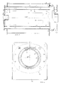
- Fig. 1 einen Längsschnitt durch den erfindungsgemäßen Heizkessel;1 shows a longitudinal section through the boiler according to the invention.
- Fig. 2 einen Querschnitt durch den Heizungskessel gemäß Fig. 1;FIG. 2 shows a cross section through the heating boiler according to FIG. 1;
- Fig. 3 - 6 im Schnitt verschiedene Ausführungsformen der Abdichtungsbereiche undFig. 3-6 in section different embodiments of the sealing areas and
- Fig. 7 einen Teilschnitt durch den Heizkessel in einer weiteren Ausführungsform.Fig. 7 shows a partial section through the boiler in a further embodiment.
Der Heizkessel besteht in bekannter Weise aus einem wasserführenden Gehäuse 16, das von einem die Brennkammer 8 und die die heizgasführenden, in Einzelzüge gegliederten Räume umschließenden Rohrzug 1 durchgriffen wird, der an einem Ende mit einem den Brenner 25 tragenden Verschluß 23 abgeschlossen ist und am anderen Ende in eine Abgassammelkammer 24 mit Abgasabzugsanschluß 24′ mündet.The boiler consists in a known manner of a water-carrying
Wie aus den Fig. 1 und 2 ersichtlich, ist der Rohrzug 1 aus flüssigkeitsdichtem Keramikmaterial gebildet, der im Bereich der Durchgriffsöffnungen 2 der Gehäusevorder- und - rückwand 3, 4 unter Ausbildung von Dichtungssitzflächen 5 geschliffen ist. Zwischen den Öffnungsrändern 6 (s. hierzu insbesondere die Fig. 3 - 6) der Gehäusevorder- und -rückwand 3, 4 und den geschliffenen Dichtungssitzflächen des äußeren Rohrzuges 1 ist dabei mindestens je eine Dichtungsring 7 plaziert. Im Rohrzug 1 sitzt ein zweiter, durchmesserkleinerer, die Brennkammer 8 umschließender und abzugsseitig mit einem eingesetzten Boden 9 versehen Rohrzug 10, der ebenfalls aus Keramikmaterial besteht. Der Boden 9 kann dabei ebenfalls aus Keramikmaterial oder aus einem anderen geeigneten, feuerfesten Material bestehen. Beim dargestellten Ausführungsbeispiel sind im ringzylindrischen Zwischenraum 11 zwischen den beiden Rohrzügen 1 und 10 Längsrippen 12 als Teile des äußeren Rohrzuges 1 vorgesehen, die, wie aus Fig. 2 ersichtlich, mit ihren freien Enden 13 an der Wand des inneren Rohrzuges 10 anliegen.As can be seen from FIGS. 1 and 2, the
Wie dargestellt, sind die beiden Rohrzüge vorteilhaft gleich lang ausgebildet, wodurch sich die beiden Rohrzüge über ihre Gesamtlänge gegenseitig abstützen können. Um einen Übergang für die Heizgaszüge aus der Brennkammer 8 in den in Einzelzüge durch die Längsrippen 12 gegliederten ringzylindrischen Zwischenraum 11 zu schaffen, ist die Heizgasüberströmöffnung 14 aus mehreren Schlitzen 14′ am inneren Rohrzug 10 gebildet, wobei jeder Schlitz 14′ zu mindestens einem der von den Längsrippen 12 begrenzten Einzelzügen 15 (Fig. 2) führt. Ggf. kann dabei ein Schlitz so breit angelegt werden, daß ein Schlitz mehrere nebeneinanderliegende Einzelzüge 15 erfaßt.As shown, the two pipe runs are advantageously of the same length, as a result of which the two pipe runs can support one another over their entire length. In order to create a transition for the heating gas flues from the
Bezüglich der Dichtungsanbringung in Form von Dichtungsringen 7 ist auf der Fig. 3 bis 6 zu verweisen. Wie aus diesen Darstellungen ersichtlich, sind die Ränder 6 der Durchgriffsöffnungen 2 der Vorder- und Rückwand 3 und 4 des Gehäuses 16 in Form von mindestens einer Ringnut 17 (Fig. 3, 4) ausgebildet, wobei diese aus den Öffnungsrandbereichen der Wände 3, 4 ausgeformt (Fig. 4, 5) oder als Zusatzteil 18 (Fig. 3) an diesen angeformt ist. Bezüglich der dabei zu beachtenden Maßgaben wird auf die diesbezüglichen obigen Erläuterungen Bezug genommen. Bevorzugt wird dabei die Ausführungsform gemäß Fig. 6, die darin besteht, daß das Zusatzteil 18 als konischer, an der Vorder- und Rückwand 3 und 4 des Gehäuses 16 befestigbarer, eine keilförmigen Zwickelraum 19 mit der Vorder- und Rückwand 3 und 4 einschließender Ringkragen 18′ ausgebildet ist, wobei die geschliffene Dichtungssitzfläche 5 mit mehreren oberflächenvergrößernden Profilierungen 20 versehen ist, in die sich der entsprechende querschnittsbemessene Dichtungsring 19 beim Festspannen des Ringkragens 18′, wie dargestellt, einpreßt.With regard to the attachment of seals in the form of
Die Ausführungsform nach Fig. 7 unterscheidet sich von der vorbeschriebenen Ausführungsform lediglich dadurch, daß diese Kesselausbildung vorteilhaft ohne besondere Dichtungen, wie vorbeschrieben, auskommt. Hierbei sitzen nämlich die beiden Keramikrohrzüge 1 und 10 in einem Rohrzug 21 aus Stahlblech, der mit der Vorder- und Rückwand 3, 4 des Gehäuses 16 flüssigkeitsdicht verbunden ist, die im übrigen, wie vorbeschrieben, ausgebildet sind. Der Rohrzug 1 steht dabei mit dem Rohrzug 21 in Berührungskontakt oder zwischen dem Rohrzug 1 und dem Rohrzug 21 ist eine elastische, wärmeleitende Masseschicht 22 angeordnet. Abgesehen von dieser abweichenden Ausführungsform ist beiden Konstruktionen gemeinsam, daß der äußere Keramikrohrzug 1 gewissermaßen "schwimmend" im wasserführenden Gehäuse 16 sitzt. In Rücksicht auf diese "schwimmende" Anordnung der Rohrzüge 1 und 10 im Gehäuse 16 sind bei beiden Ausführungsformen der den Brenner 25 tragende Verschluß 23 und die Abgassammelkammer 24 kontaktfrei zu den beiden Rohrzügen 1 und 10 an der Vorder- und Rückwand 3, 4 des Gehäuses 16 in zweckentsprechender Weise befestigt. Dadurch sind die beiden Keramikrohrzüge 1 und 10 nicht fest in das Gehäuse 16 eingebunden und Längsausdehnungen der beiden Keramikrohrzüge 1 und 10 steht nichts entgegen.The embodiment according to FIG. 7 differs from the previously described embodiment only in that this boiler design advantageously does without special seals, as described above. This is because the two ceramic pipe runs 1 and 10 are seated in a pipe run 21 made of sheet steel, which is connected to the front and
Bezüglich des wasserführenden Gehäuses 16 ist im übrigen darauf hinzuweisen, daß dieses keineswegs zwingend aus Stahlblech bestehen muß, sondern auch bspw. aus Grauguß, Aluminium, Edelstahl oder selbst sogar aus Keramik gebildet sein kann. Selbst bei einer Ausbildung des Gehäuses 16 aus Keramik ist dabei die "schwimmende" Einbindung der beiden Rohrzüge 1 und 10 wesentlich, da das Gehäuse 16, weil gekühlt, anderen Wärmebelastungen unterworfen ist als die beiden Rohrzüge 1 und 10.With regard to the water-carrying
Claims (9)
Priority Applications (1)
| Application Number | Priority Date | Filing Date | Title |
|---|---|---|---|
| AT89103568T ATE77470T1 (en) | 1988-03-03 | 1989-03-01 | BOILER. |
Applications Claiming Priority (2)
| Application Number | Priority Date | Filing Date | Title |
|---|---|---|---|
| DE3806804 | 1988-03-03 | ||
| DE3806804A DE3806804A1 (en) | 1988-03-03 | 1988-03-03 | HEATING BOILER |
Publications (3)
| Publication Number | Publication Date |
|---|---|
| EP0331141A2 EP0331141A2 (en) | 1989-09-06 |
| EP0331141A3 EP0331141A3 (en) | 1990-04-18 |
| EP0331141B1 true EP0331141B1 (en) | 1992-06-17 |
Family
ID=6348660
Family Applications (1)
| Application Number | Title | Priority Date | Filing Date |
|---|---|---|---|
| EP89103568A Expired - Lifetime EP0331141B1 (en) | 1988-03-03 | 1989-03-01 | Boiler |
Country Status (3)
| Country | Link |
|---|---|
| EP (1) | EP0331141B1 (en) |
| AT (1) | ATE77470T1 (en) |
| DE (2) | DE3806804A1 (en) |
Citations (2)
| Publication number | Priority date | Publication date | Assignee | Title |
|---|---|---|---|---|
| DE2645717A1 (en) * | 1976-10-09 | 1978-04-13 | Hans Viessmann | BOILERS FOR BURNING LIQUID OR GAS FUELS |
| DE3331340A1 (en) * | 1983-08-31 | 1985-04-11 | Buderus Ag, 6330 Wetzlar | Central heating boiler |
Family Cites Families (7)
| Publication number | Priority date | Publication date | Assignee | Title |
|---|---|---|---|---|
| DE2906362C2 (en) * | 1979-02-19 | 1981-02-05 | Hans 3559 Battenberg Viessmann | Heating boilers for liquid or gaseous fuels |
| DE3014245C2 (en) * | 1980-04-14 | 1984-06-28 | Kernforschungsanlage Jülich GmbH, 5170 Jülich | Combustion and heating device with a ceramic burner head |
| DE3025651C2 (en) * | 1980-07-07 | 1983-02-17 | Hans 3559 Battenberg Vießmann | Heating boiler |
| DE3413968A1 (en) * | 1984-03-31 | 1985-10-10 | Didier-Werke Ag, 6200 Wiesbaden | Device for combustion support for an oil burner or gas burner |
| US4538551A (en) * | 1984-06-20 | 1985-09-03 | Vapor Corporation | Refractory choke for a high intensity combustor |
| DE3425259C2 (en) * | 1984-07-10 | 1986-10-23 | Wolfgang 5063 Overath Schmitter | Heat generator |
| DE3535341A1 (en) * | 1985-10-03 | 1987-04-09 | Viessmann Hans | BOILER FOR LIQUID OR GASEOUS FUELS |
-
1988
- 1988-03-03 DE DE3806804A patent/DE3806804A1/en not_active Withdrawn
-
1989
- 1989-03-01 EP EP89103568A patent/EP0331141B1/en not_active Expired - Lifetime
- 1989-03-01 AT AT89103568T patent/ATE77470T1/en not_active IP Right Cessation
- 1989-03-01 DE DE8989103568T patent/DE58901651D1/en not_active Expired - Lifetime
Patent Citations (2)
| Publication number | Priority date | Publication date | Assignee | Title |
|---|---|---|---|---|
| DE2645717A1 (en) * | 1976-10-09 | 1978-04-13 | Hans Viessmann | BOILERS FOR BURNING LIQUID OR GAS FUELS |
| DE3331340A1 (en) * | 1983-08-31 | 1985-04-11 | Buderus Ag, 6330 Wetzlar | Central heating boiler |
Also Published As
| Publication number | Publication date |
|---|---|
| DE3806804A1 (en) | 1989-09-14 |
| EP0331141A2 (en) | 1989-09-06 |
| EP0331141A3 (en) | 1990-04-18 |
| DE58901651D1 (en) | 1992-07-23 |
| ATE77470T1 (en) | 1992-07-15 |
Similar Documents
| Publication | Publication Date | Title |
|---|---|---|
| DE4116692A1 (en) | HEAT EXCHANGER INSERT FOR AIR HEATERS | |
| DE2629962C2 (en) | Device for soundproofing a radiant heating tube for an industrial furnace | |
| DE2721832A1 (en) | BOILER | |
| EP0331141B1 (en) | Boiler | |
| DE3601000A1 (en) | Water-heating boiler | |
| DE1168929B (en) | Tubular heat exchanger element | |
| DE2814155A1 (en) | Heat exchanger for boiler - has stair cross-section flue gas tube enclosed by water jacket | |
| EP0711954B1 (en) | Air/flue gas stack | |
| EP0387584B1 (en) | Heating gas draft tube | |
| AT395209B (en) | HEATING DEVICE | |
| DE3327140A1 (en) | GAS BURNER, ESPECIALLY FOR LIQUID GAS, FOR INSTALLATION IN A HEAT EXCHANGER | |
| CH635189A5 (en) | Heating boiler for burning liquid or gaseous fuels | |
| DE951999C (en) | Flue pipe heat exchanger for exhaust gases | |
| DE10158299A1 (en) | Water tube boiler | |
| DE3045387C2 (en) | Flue gas heat exchanger | |
| DE2025472C3 (en) | Heating boiler | |
| DE3940165C1 (en) | ||
| DE2856338B2 (en) | Heating boilers for liquid or gaseous fuels | |
| EP0617242A2 (en) | Three-pass boiler | |
| EP0430061B1 (en) | Boiler | |
| DE7305328U (en) | Multi-pass boiler | |
| DE2361834A1 (en) | Boiler plant with fresh air shaft - has opening to atmosphere in region of opening of flue gas shaft at chimney top | |
| EP1058057A1 (en) | Balanced flue element | |
| DE3506640A1 (en) | Mixing head for a gasification oil burner | |
| LU85997A1 (en) | HEATING BOILER FOR LIQUID OR GASEOUS FUELS |
Legal Events
| Date | Code | Title | Description |
|---|---|---|---|
| PUAI | Public reference made under article 153(3) epc to a published international application that has entered the european phase |
Free format text: ORIGINAL CODE: 0009012 |
|
| AK | Designated contracting states |
Kind code of ref document: A2 Designated state(s): AT BE CH DE FR GB IT LI NL |
|
| PUAL | Search report despatched |
Free format text: ORIGINAL CODE: 0009013 |
|
| AK | Designated contracting states |
Kind code of ref document: A3 Designated state(s): AT BE CH DE FR GB IT LI NL |
|
| 17P | Request for examination filed |
Effective date: 19900411 |
|
| 17Q | First examination report despatched |
Effective date: 19910115 |
|
| GRAA | (expected) grant |
Free format text: ORIGINAL CODE: 0009210 |
|
| AK | Designated contracting states |
Kind code of ref document: B1 Designated state(s): AT BE CH DE FR GB IT LI NL |
|
| REF | Corresponds to: |
Ref document number: 77470 Country of ref document: AT Date of ref document: 19920715 Kind code of ref document: T |
|
| ET | Fr: translation filed | ||
| REF | Corresponds to: |
Ref document number: 58901651 Country of ref document: DE Date of ref document: 19920723 |
|
| ITF | It: translation for a ep patent filed |
Owner name: MODIANO & ASSOCIATI S.R |
|
| GBT | Gb: translation of ep patent filed (gb section 77(6)(a)/1977) | ||
| PLBE | No opposition filed within time limit |
Free format text: ORIGINAL CODE: 0009261 |
|
| STAA | Information on the status of an ep patent application or granted ep patent |
Free format text: STATUS: NO OPPOSITION FILED WITHIN TIME LIMIT |
|
| 26N | No opposition filed | ||
| PGFP | Annual fee paid to national office [announced via postgrant information from national office to epo] |
Ref country code: GB Payment date: 19990225 Year of fee payment: 11 |
|
| PGFP | Annual fee paid to national office [announced via postgrant information from national office to epo] |
Ref country code: BE Payment date: 19990303 Year of fee payment: 11 |
|
| PGFP | Annual fee paid to national office [announced via postgrant information from national office to epo] |
Ref country code: CH Payment date: 19990326 Year of fee payment: 11 |
|
| PGFP | Annual fee paid to national office [announced via postgrant information from national office to epo] |
Ref country code: NL Payment date: 19990331 Year of fee payment: 11 Ref country code: FR Payment date: 19990331 Year of fee payment: 11 Ref country code: DE Payment date: 19990331 Year of fee payment: 11 Ref country code: AT Payment date: 19990331 Year of fee payment: 11 |
|
| PG25 | Lapsed in a contracting state [announced via postgrant information from national office to epo] |
Ref country code: GB Free format text: LAPSE BECAUSE OF NON-PAYMENT OF DUE FEES Effective date: 20000301 Ref country code: AT Free format text: LAPSE BECAUSE OF NON-PAYMENT OF DUE FEES Effective date: 20000301 |
|
| PG25 | Lapsed in a contracting state [announced via postgrant information from national office to epo] |
Ref country code: LI Free format text: LAPSE BECAUSE OF NON-PAYMENT OF DUE FEES Effective date: 20000331 Ref country code: CH Free format text: LAPSE BECAUSE OF NON-PAYMENT OF DUE FEES Effective date: 20000331 Ref country code: BE Free format text: LAPSE BECAUSE OF NON-PAYMENT OF DUE FEES Effective date: 20000331 |
|
| BERE | Be: lapsed |
Owner name: VIESSMANN HANS Effective date: 20000331 |
|
| PG25 | Lapsed in a contracting state [announced via postgrant information from national office to epo] |
Ref country code: NL Free format text: LAPSE BECAUSE OF NON-PAYMENT OF DUE FEES Effective date: 20001001 |
|
| GBPC | Gb: european patent ceased through non-payment of renewal fee |
Effective date: 20000301 |
|
| REG | Reference to a national code |
Ref country code: CH Ref legal event code: PL |
|
| PG25 | Lapsed in a contracting state [announced via postgrant information from national office to epo] |
Ref country code: FR Free format text: LAPSE BECAUSE OF NON-PAYMENT OF DUE FEES Effective date: 20001130 |
|
| NLV4 | Nl: lapsed or anulled due to non-payment of the annual fee |
Effective date: 20001001 |
|
| REG | Reference to a national code |
Ref country code: FR Ref legal event code: ST |
|
| PG25 | Lapsed in a contracting state [announced via postgrant information from national office to epo] |
Ref country code: DE Free format text: LAPSE BECAUSE OF NON-PAYMENT OF DUE FEES Effective date: 20010103 |
|
| PG25 | Lapsed in a contracting state [announced via postgrant information from national office to epo] |
Ref country code: IT Free format text: LAPSE BECAUSE OF NON-PAYMENT OF DUE FEES;WARNING: LAPSES OF ITALIAN PATENTS WITH EFFECTIVE DATE BEFORE 2007 MAY HAVE OCCURRED AT ANY TIME BEFORE 2007. THE CORRECT EFFECTIVE DATE MAY BE DIFFERENT FROM THE ONE RECORDED. Effective date: 20050301 |