EP0330554A1 - Verfahren und Vorrichtung zur kontinuierlichen Herstellung von Betonbauten - Google Patents
Verfahren und Vorrichtung zur kontinuierlichen Herstellung von Betonbauten Download PDFInfo
- Publication number
- EP0330554A1 EP0330554A1 EP89400451A EP89400451A EP0330554A1 EP 0330554 A1 EP0330554 A1 EP 0330554A1 EP 89400451 A EP89400451 A EP 89400451A EP 89400451 A EP89400451 A EP 89400451A EP 0330554 A1 EP0330554 A1 EP 0330554A1
- Authority
- EP
- European Patent Office
- Prior art keywords
- blade
- concrete
- produced
- lift
- blades
- Prior art date
- Legal status (The legal status is an assumption and is not a legal conclusion. Google has not performed a legal analysis and makes no representation as to the accuracy of the status listed.)
- Withdrawn
Links
Images


Classifications
-
- E—FIXED CONSTRUCTIONS
- E02—HYDRAULIC ENGINEERING; FOUNDATIONS; SOIL SHIFTING
- E02B—HYDRAULIC ENGINEERING
- E02B7/00—Barrages or weirs; Layout, construction, methods of, or devices for, making same
- E02B7/02—Fixed barrages
- E02B7/04—Dams across valleys
- E02B7/08—Wall dams
Definitions
- the invention relates to a method and a device for the continuous production of concrete structures.
- construction joints are generally designed to be able to transmit shear forces in their plane and this requires, according to traditional methods, complicated formwork.
- the object of the present invention is in particular to remedy these drawbacks and to this end relates to a process for the continuous production of concrete structures, characterized in that adjacent concrete levees are produced successively by separating these lifts constituted by a thin blade, this blade not having in itself a structure sufficient to withstand the thrust of a concrete lift, this blade is properly supported by support means, the first concrete lift is carried out then, in the second place, the adjacent concrete is lifted while keeping the blade thus embedded in the concrete and which materializes the limit between the two studs.
- grout injection devices are fixed on the blade, these devices being connected by their supply tube.
- the devices and their feed tube are arranged on the side of the blade receiving in support the first lift of concrete in order to carry out, via these devices, the injection of the grout the space between the opposite side of the blade and the second adjacent concrete lift.
- positioning devices projecting from the face of the blade arranged on the side of the first concrete lift to be produced are fixed on the blade.
- the blades are arranged so that they pass right through the thickness of the structure to be produced, these blades extending to formwork facing the structure.
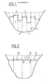
- the object of the present invention is therefore the economical construction of structures in vibrated or compacted concrete, according to which (see FIG. 2) successive lifting of adjacent concrete is carried out 51, 52, 53 by incorporating in each case limits 6 between the corresponding studs, a thin blade lost in perennial material (metal or synthetic product).
- This arrangement makes it possible to carry out the lifting of concrete 51, 52, 53, continuously, that is to say to successively carry out neighboring lifting, from one end of the structure to the other, in the direction of arrow F in FIG. 2, these lifts creating only a slight level difference between them.
- blades arranged transversely to the structure, terminate by their lateral edges, up to the facing faces of the structure, the latter thus being able to be shuttered without discontinuity at the joints, which considerably simplifies the production of this shuttering, by facilitating obtaining a suitable seal between the blades and the shuttering which is perpendicular to it.
- These thin blades consist of thin sheets or plates of metal or plastic, the thickness of which may be of a millimeter order, that is to say d 'A structure such that the rigidity of the blade is in itself insufficient to contain the thrust of the concrete of the lifting in progress.
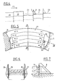
- Support means such as 8 in FIGS. 3b and 3c, will be provided on the face of the blade opposite to that receiving the concrete, in order to keep it in position.
- these support means 8 forming the support structures are removable and are intended to be removed before pouring the next concrete lift.
- these support means may be provided in the form of lost devices remaining embedded in the structure after its completion.
- the latter can be produced either in a single element, or in several elements overlapping each other to form a continuous joint surface.
- the lost blade 7 is embedded between two adjacent concrete studs 9 and 10, the stud 10 produced in the second place forming or not a slight projection relative to the previous stud 9, the limit between the two studs being materialized by the blade 7, the upper end of which ends at the upper surface of the stud 10.
- the formulation of concrete for the construction of the works will preferably be carried out in order to have a good skeleton of large aggregates and a mortar with a minimum cement dosage but rich in paste, by means of auxiliary fines. quality controlled.
- additives plasticizers, water reducers, air entrainers
- the formwork is then allowed, provided that the concrete surface does not tear off, which is avoided by keeping the lost blade in position by the use of holding members 11 ( Figure 3b) engaged in concrete.
- These members are fixed to the blade 7 in order to form projections on the face of the blade disposed on the side of the concrete lift to be produced in the first place, that is to say on the side opposite to the face which is supported by the support means 8.
- This blade is provided, on the side of the concrete lift to be produced, holding means 11 as well as devices 13 allowing the injection of a cement or other grout into the space which is formed between the two adjacent studs, after setting concrete secondly made stud.
- the lost blade 7 therefore ensures, during the vibration of the concrete and this until its cohesion is sufficient, the resumption of the thrusts by relying on removable, rigid and light elements 8, easy to set up according to the layout of the desired joint and easy to remove before concreting the neighboring stud.
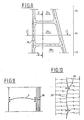
- these removable elements can be replaced by rigid rigid elements, rising with the joint and constituted, for example (see FIG. 13), by tubes or bars 17 which successively fit one into the other and placed on the side of the blade which is opposite to that which receives the concrete lift.
- rigid rigid elements rising with the joint and constituted, for example (see FIG. 13)
- tubes or bars 17 which successively fit one into the other and placed on the side of the blade which is opposite to that which receives the concrete lift.
- a guy line system 18 formed by cables and connecting the upper end of the tubes 17 to piles 19 inserted in the lower stud.
- Each concrete lift is obtained, for example (see Figure 3c) by depositing three successive layers of concrete which are each spread and vibrated or compacted and when the lift has sufficient cohesion, the support means 8 are removed, as far as where they are removable, then we proceed, in successive layers, to the realization of the adjacent lift 20 (figure 3d) poured by resting on the opposite face of the blade 7. After hardening of the concrete of the two adjacent liftings 14 and 20 and as a result of the removal of this concrete, a space is created between the face of the blade 7 which is opposite to that comprising the holding members 11 and the opposite face of the pad 20, that is to say on the side of the concrete which is poured in the second place.
- this strip may be coated with a product preventing the bonding of the fresh concrete. This will give a good formation and a good position of this space, into which will then be injected, under pressure, a filling grout restoring the mechanical continuity of the structure and improving its sealing.
- the studs 21 and 22 have already been made, the concrete of the stud 21 being already hardened.
- the formwork is then removed from the facings located at the height of this stud 22, in order to transfer them downstream, and for example with a view to producing the stud 24.
- the blades 7 have in themselves, given their thinness, a certain degree of deformability, making it possible to give the joint connecting two adjacent studs a particular shape favoring the nesting of the studs to help prevent their displacement relative by shear.
- the material and the thickness of these blades will therefore be such that they have sufficient deformability in their plane, to make it possible to easily obtain, on site, the desired geometry.
- This geometry is maintained by an independent lost or removable support structure, which is itself designed as a function of the rigidity of the blade used, so that this structure can withstand the thrusts of the concrete and, in particular, those which are related to the liquefaction of concrete during its vibration.
- This blade which is waterproof to laitance and which is integral with the concrete on one of its faces by means of the anchoring devices, could for example be produced in a curved form 26, as shown in FIG. 5, in order to produce adjacent studs which fit into each other by complementary concave / convex faces separated by this curved blade 26.
- the pouring of the concrete to carry out the lifting 27 will be carried out in successive layers, preferably respecting, for each layer, the direction and the chronology of the deposits materialized by the arrows referenced from a to e.
- the lifting is delimited by the facing formwork 28 and 29 and by the two blades 26, one of which is held against the stud previously produced and the other of which is held in position by the support means 8 .
- a sealing strip 38 intended to be sealed by its two lateral edges in adjacent studs.
- This strip which extends near the periphery of the lateral face of the two adjacent studs, delimits between a lateral face of the most recent concrete stud and the opposite face of the blade anchored in the oldest stud, a compartment watertight into which will then be injected, via the conduits 32 (see Figure 7), the cement grout or the like having to form the joint between the two studs.
- FIG 8 there is thus shown in vertical cross section, a concrete structure and in particular a dam comprising three successive levels 33, 34 and 35 of studs, whose lateral faces delimited by the deformable blades, are surrounded by bands of joint 38 forming, for each pad, a sealed compartment 331, 341, 351.
- the grout In these compartments is injected the grout to constitute the joint and ensuring the intimate connection between the two adjacent studs, this joint reconstituting a homogeneous structure ensuring a regular distribution of the loads.
- the blades 26 are bent to form curved cylinder portions, the generators of which are located vertically in the structure. Any other arrangement may however be considered, depending on the nature of the work, its dimensions and its shape.
- this curved blade will be straight.
- FIG 11 there is shown a blade which is provided, on one of its faces, projecting elements forming the holding members in position on the oldest concrete.
- These holding members are, in the example shown, produced in the form of flattened "V" folded blades, fixed by any means (welding, riveting, bonding, etc.) to the blade.
- These holding devices can be produced in very different ways from rods, blades or folded, cut or stamped plates, to allow an energetic positioning of the blade on the concrete without altering the possibilities of shaping this blade and also without allowing the flow of milt during the vibration.
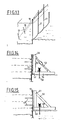
- This plate 7 also comprises, on its face disposed on the side of the oldest concrete, that is to say on the side of the holding members 11, an attached band delimiting the slot 12 allowing the vertical covering of the blades, as well as orifices in which the injection fittings 40 and their valve are fixed.
- the lost blade 7 made of metal or plastic can also be produced in the form of a complex material and, for example, in the form of a flexible material, of the tarpaulin type, suitably reinforced (see FIG. 12).
- the blade corresponding to a lift can be formed of several flexible blades 51 returned in 511 in the concrete lift at each layer and over a few tens of centimeters, in order to achieve a suitable maintenance of this blade part.
- the injection devices are fixed on rigid elements 52 placed on the previous layer and connecting to the flexible elements 51 of the blade.
- the injection devices supplied by the tubes 41 can be produced by cuffs 42 (see FIG. 18) implemented on the non-anchored side of the blade 7 and covered with a protective cover 43 preventing the cuff from being blocked 42 in concrete.
- the valve of the injection device will preferably be constituted by a block of flexible material, elastically deformable, applying to the opposite non-anchored face of the blade 7 in order to deform and allow the passage of the grout when the latter is brought under sufficient pressure by the flexible tubes 41 into the valve bodies connected in series.
- the assembly of a valve body and its valve on either side of an orifice of the blade 7 (constituting the injection device 40), will preferably be produced by screwing through the orifice of this blade or by gluing.
- the flexible valve will be adjusted by tightening screws to adjust the opening pressure.
- the injection of grout is possible at the same place where creates the opening under the effect of the withdrawal of the concrete, that is to say on the side of the blade 7 which is not integral with the concrete.
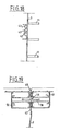
- each compartment is provided in its lower part with a primary injection ramp 44 (see FIG. 16) constituted by a sleeve tube 42 (see FIG. 18).
- the valves are distributed with sufficient density to allow homogeneous filling of the open joint space with suitably fluidized and delayed grout.
- the role of the valves is, in particular, to authorize any subsequent reinjection of the compartment.
- Each injection compartment 331, 341, 351 also comprises, in its upper part (see FIG. 16) a collecting gutter 45 provided against the smooth face of the blade 7 in order to ensure the return of the grout after filling of the chamber delimited by the sealing strip 38.
- Each injection compartment 331, 341, 351 is of a shape which is determined by the trace of the blade, its periphery being delimited by the seal 38. However, this seal should cross the blade at its periphery and , for this purpose, this seal 38 is disposed (see FIG. 19) in a slot 46 formed between two blades 47 and 48.
- One, 47, of these blades is located on the internal side relative to the slot and is fixed at the periphery of the blade 7 and the other, 48, external with respect to this slot, is maintained at a determined spacing from the blade 47 by two rigid reinforcing cages 49 and 50 located on either side of these blades 47, 48.
- This arrangement also makes it possible to rigidly position the sealing strip 38 without making a mechanical connection with the facing formwork.
- the support elements ensuring the support of the blade lost during concreting can be produced in various ways, but preferably so as to be able to adapt to the shape that it is desired to give to this blade.
- these support or support elements consist of tubes 17 anchored to the base in the directly lower stud and which can be bent longitudinally of the desired degree by exerting a determined tension on the stay cables 18.
- These support elements can also be produced (see FIG. 14) in the form of stays 53 adjustable in length and determining the angle formed between a base 54 and a support element 55 provided with chevrons 56.
- This element of support 55 is mounted articulated on the base 54 via a pin 57, this base 54 being positioned on the upper face of the lower level stud by anchoring stops 58.
Landscapes
- Engineering & Computer Science (AREA)
- Structural Engineering (AREA)
- General Engineering & Computer Science (AREA)
- Mechanical Engineering (AREA)
- Civil Engineering (AREA)
- On-Site Construction Work That Accompanies The Preparation And Application Of Concrete (AREA)
Applications Claiming Priority (2)
| Application Number | Priority Date | Filing Date | Title |
|---|---|---|---|
| FR8802093A FR2627524B1 (fr) | 1988-02-22 | 1988-02-22 | Procede et dispositif pour la realisation en continu d'ouvrages en beton |
| FR8802093 | 1988-02-22 |
Publications (1)
| Publication Number | Publication Date |
|---|---|
| EP0330554A1 true EP0330554A1 (de) | 1989-08-30 |
Family
ID=9363480
Family Applications (1)
| Application Number | Title | Priority Date | Filing Date |
|---|---|---|---|
| EP89400451A Withdrawn EP0330554A1 (de) | 1988-02-22 | 1989-02-17 | Verfahren und Vorrichtung zur kontinuierlichen Herstellung von Betonbauten |
Country Status (3)
| Country | Link |
|---|---|
| EP (1) | EP0330554A1 (de) |
| FR (1) | FR2627524B1 (de) |
| NO (1) | NO890738L (de) |
Cited By (1)
| Publication number | Priority date | Publication date | Assignee | Title |
|---|---|---|---|---|
| CN102587381A (zh) * | 2012-04-09 | 2012-07-18 | 浙江大学 | 一种利用双膨胀水泥浇筑大坝的方法 |
Citations (7)
| Publication number | Priority date | Publication date | Assignee | Title |
|---|---|---|---|---|
| US1628933A (en) * | 1925-11-11 | 1927-05-17 | Arthur E Troiel | Method of grouting |
| US2961731A (en) * | 1953-02-20 | 1960-11-29 | Dow A Buzzell | Means and method for molding concrete sections of hydraulic concrete structures |
| US3120047A (en) * | 1961-05-04 | 1964-02-04 | John M Crom | Method of making a liquid impervious wall |
| US3452546A (en) * | 1967-04-21 | 1969-07-01 | Gen Forages C O F O R Cie | Steel pile assembly for the erection of underground concrete walls |
| US3893302A (en) * | 1973-10-25 | 1975-07-08 | Rapidex Inc | Machine and method for excavating trenches and for constructing walls in trenches |
| EP0039661A2 (de) * | 1980-05-01 | 1981-11-11 | Heinz Witschi | Verwendung von Streckmetall als verlorene Abschalung |
| EP0093697A2 (de) * | 1982-05-04 | 1983-11-09 | Heinz Witschi | Verfahren und Anlage zur Herstellung eines als verlorene Abschalung verwendbaren Profilelementes |
Family Cites Families (1)
| Publication number | Priority date | Publication date | Assignee | Title |
|---|---|---|---|---|
| DE2944385A1 (de) * | 1979-11-02 | 1981-05-14 | Josef Riepl Bau-Aktiengesellschaft, 8000 München | Verfahren zum herstellen von schlitzwaenden |
-
1988
- 1988-02-22 FR FR8802093A patent/FR2627524B1/fr not_active Expired - Lifetime
-
1989
- 1989-02-17 EP EP89400451A patent/EP0330554A1/de not_active Withdrawn
- 1989-02-21 NO NO89890738A patent/NO890738L/no unknown
Patent Citations (7)
| Publication number | Priority date | Publication date | Assignee | Title |
|---|---|---|---|---|
| US1628933A (en) * | 1925-11-11 | 1927-05-17 | Arthur E Troiel | Method of grouting |
| US2961731A (en) * | 1953-02-20 | 1960-11-29 | Dow A Buzzell | Means and method for molding concrete sections of hydraulic concrete structures |
| US3120047A (en) * | 1961-05-04 | 1964-02-04 | John M Crom | Method of making a liquid impervious wall |
| US3452546A (en) * | 1967-04-21 | 1969-07-01 | Gen Forages C O F O R Cie | Steel pile assembly for the erection of underground concrete walls |
| US3893302A (en) * | 1973-10-25 | 1975-07-08 | Rapidex Inc | Machine and method for excavating trenches and for constructing walls in trenches |
| EP0039661A2 (de) * | 1980-05-01 | 1981-11-11 | Heinz Witschi | Verwendung von Streckmetall als verlorene Abschalung |
| EP0093697A2 (de) * | 1982-05-04 | 1983-11-09 | Heinz Witschi | Verfahren und Anlage zur Herstellung eines als verlorene Abschalung verwendbaren Profilelementes |
Cited By (1)
| Publication number | Priority date | Publication date | Assignee | Title |
|---|---|---|---|---|
| CN102587381A (zh) * | 2012-04-09 | 2012-07-18 | 浙江大学 | 一种利用双膨胀水泥浇筑大坝的方法 |
Also Published As
| Publication number | Publication date |
|---|---|
| FR2627524A1 (fr) | 1989-08-25 |
| NO890738L (no) | 1989-08-23 |
| NO890738D0 (no) | 1989-02-21 |
| FR2627524B1 (fr) | 1991-06-21 |
Similar Documents
| Publication | Publication Date | Title |
|---|---|---|
| EP2390420B1 (de) | Schlitzwand mit vorgefertigter Hohllamelle und Verfahren zur Herstellung einer solchen Wand | |
| EP0089861B1 (de) | Verfahren zum Verstärken von Gewölben oder ähnlichen Konstruktionen | |
| EP0166656B1 (de) | Vorgefertigte Stützelemente zum Schutz, Verstärken und/oder Bekleiden von Ausschachtungen, Anker- und Verbindungsvorrichtungen und Verfahren zum Anwenden dieser Elemente und Vorrichtungen | |
| FR2669259A1 (fr) | Procede de fabrication de voussoirs prefabriques. | |
| EP0381547B1 (de) | Verfahren zur Herstellung einer vergrabenen Leitung | |
| EP0285465B1 (de) | Bauelement, insbesondere Verkleidungselement mit integrierter Wärmedämmung | |
| EP0833987B1 (de) | Durchgehend verstärkte trennwand, zugehorige herstellungsverfahren und schalung | |
| EP0028558B1 (de) | Verfahren zum Verbessern des Gleitwiderstandes von einer Baukonstruktion und ihre Fundierung | |
| EP0330554A1 (de) | Verfahren und Vorrichtung zur kontinuierlichen Herstellung von Betonbauten | |
| FR2903437A1 (fr) | Element prefabrique pour la realisation d'une paroi en beton arme et paroi ainsi realisee | |
| EP0568441A1 (de) | Tragstruktur wie zum Beispiel eine Decke, mit Trägern und einer Betonplatte und Verfahren zu ihrer Herstellung | |
| FR2721988A1 (fr) | Conduite de circulation de fluide | |
| EP2563975B1 (de) | Formteilwand mit fertigteilverkleidung | |
| FR2727447A1 (fr) | Ouvrage de passage sous remblai et son procede de realisation | |
| EP0360682B1 (de) | Dehnungsfuge für Betonbodenbelag | |
| FR2750442A1 (fr) | Nouvelle paroi drainante, procede pour sa realisation et element mis en oeuvre | |
| EP2231947A1 (de) | Vorgefertigtes element zur herstellung einer stahlbetonplatte und so hergestellte platte | |
| FR2473085A1 (fr) | Procede pour assurer la continuite des armatures entre des panneaux successifs d'une paroi en beton arme, et panier d'armatures pour la mise en oeuvre de ce procede | |
| EP0584298B1 (de) | Langförmige abdeckung grossen durchmessers sowie herstellungsverfahren | |
| FR2600359A1 (fr) | Dispositif pour faciliter le maconnage d'elements de construction | |
| FR2548247A1 (fr) | Piece de formes en materiaux legers a champs identiques, symetriques ou inversables, notamment pour l'etancheite thermique, electrique ou phonique de tous volumes | |
| FR2732701A1 (fr) | Dalles decoratives a elements moules preappareilles sur trame et procede de mise en oeuvre | |
| FR2458644A1 (fr) | Dalle-tuile | |
| FR2738580A1 (fr) | Structure de tablier de pont et procede pour realiser le tablier | |
| FR3105274A3 (fr) | Procédé de formation d'une couche de construction dotée d'un passage |
Legal Events
| Date | Code | Title | Description |
|---|---|---|---|
| PUAI | Public reference made under article 153(3) epc to a published international application that has entered the european phase |
Free format text: ORIGINAL CODE: 0009012 |
|
| AK | Designated contracting states |
Kind code of ref document: A1 Designated state(s): AT BE CH DE ES GB GR IT LI LU NL SE |
|
| 17P | Request for examination filed |
Effective date: 19900102 |
|
| 17Q | First examination report despatched |
Effective date: 19910920 |
|
| STAA | Information on the status of an ep patent application or granted ep patent |
Free format text: STATUS: THE APPLICATION IS DEEMED TO BE WITHDRAWN |
|
| 18D | Application deemed to be withdrawn |
Effective date: 19920131 |