EP0166656B1 - Vorgefertigte Stützelemente zum Schutz, Verstärken und/oder Bekleiden von Ausschachtungen, Anker- und Verbindungsvorrichtungen und Verfahren zum Anwenden dieser Elemente und Vorrichtungen - Google Patents
Vorgefertigte Stützelemente zum Schutz, Verstärken und/oder Bekleiden von Ausschachtungen, Anker- und Verbindungsvorrichtungen und Verfahren zum Anwenden dieser Elemente und Vorrichtungen Download PDFInfo
- Publication number
- EP0166656B1 EP0166656B1 EP85401227A EP85401227A EP0166656B1 EP 0166656 B1 EP0166656 B1 EP 0166656B1 EP 85401227 A EP85401227 A EP 85401227A EP 85401227 A EP85401227 A EP 85401227A EP 0166656 B1 EP0166656 B1 EP 0166656B1
- Authority
- EP
- European Patent Office
- Prior art keywords
- elements
- prefabricated
- fact
- anchors
- ground
- Prior art date
- Legal status (The legal status is an assumption and is not a legal conclusion. Google has not performed a legal analysis and makes no representation as to the accuracy of the status listed.)
- Expired
Links
Images


Classifications
-
- E—FIXED CONSTRUCTIONS
- E02—HYDRAULIC ENGINEERING; FOUNDATIONS; SOIL SHIFTING
- E02D—FOUNDATIONS; EXCAVATIONS; EMBANKMENTS; UNDERGROUND OR UNDERWATER STRUCTURES
- E02D29/00—Independent underground or underwater structures; Retaining walls
- E02D29/02—Retaining or protecting walls
- E02D29/0258—Retaining or protecting walls characterised by constructional features
- E02D29/0266—Retaining or protecting walls characterised by constructional features made up of preformed elements
-
- E—FIXED CONSTRUCTIONS
- E02—HYDRAULIC ENGINEERING; FOUNDATIONS; SOIL SHIFTING
- E02D—FOUNDATIONS; EXCAVATIONS; EMBANKMENTS; UNDERGROUND OR UNDERWATER STRUCTURES
- E02D17/00—Excavations; Bordering of excavations; Making embankments
- E02D17/02—Foundation pits
- E02D17/04—Bordering surfacing or stiffening the sides of foundation pits
Definitions
- the invention relates to a method of coating and / or supporting with prefabricated coating elements of the walls of natural or artificial excavations in the ground, such as slopes, banks, trenches, wells, tunnels, etc. , according to which an excavation having a wall is made in the ground.
- Such a method relates, in particular, to the protection, reinforcement, or stabilization of land.
- the realization of a retaining wall requires an excavation whose initial volume is greater than the final space.
- Cladding walls are placed from the bottom up, and hooking elements are placed in the free space located behind the cladding elements; a layer of soil is then poured to fill the space behind the covering elements and to cover the anchoring elements corresponding to a row of covering elements; this layer of land is then compacted.
- the object of the invention is, above all, to provide a method of coating and / or supporting excavation walls which makes it possible to obtain, with a minimum of operations, the desired coating with optimal anchoring in a ground which has suffered a minimum of disorders. It is further desired that this process makes it possible to ensure the coating and / or the support of excavation walls as and when these excavations are carried out. It is moreover desirable that such a process leads to a coating having good phonic, sealing and aesthetic qualities.
- the prefabricated covering elements have a through hole for the anchoring reinforcement.
- the prefabricated elements can include specific tamping holes.
- the stuffing can be put in place using the existing holes in the covering elements, either anchor holes or specific stuffing holes.
- the prefabricated elements are essentially full, that is to say that the total area of the openings possibly formed in these elements is less than 30% of the total area of the element.
- the number of prefabricated elements fixed to reinforcements sealed in the ground (and therefore the number of reinforcements sealed in the ground) can be at most equal to half the number of prefabricated elements.
- the number of sealing reinforcements, and therefore the number of prefabricated elements fixed to these reinforcements is equal to one third of the total number of prefabricated elements.
- the jam may consist of a lean mortar or a swelling product.
- the prefabricated elements can be identical; they can be placed alternately on the front and back.
- connection means between the prefabricated elements can be constituted either by assembly means of the “dry” type such as grooves or notches male and female conjugate, or by assembly means involving a sealant of the mortar type, resin or other, the edges of the prefabricated elements being provided with grooves intended to receive the sealant.
- the blocking of the prefabricated elements on the frameworks sealed in the ground is generally carried out after the injection of the tamping.
- the prefabricated elements intended to be fixed to sealing reinforcements, may include a reinforced zone provided with a hole for passage of the sealing reinforcement, this reinforced zone being provided in particular in the central region of said element.
- the prefabricated elements can have a hexagonal or circular shape. They can be made of concrete, binders or composite materials.
- Anchoring frames 2 are sealed in the ground S and protrude from the wall 1, by parts 3 provided at their external ends with fixing elements such as a thread capable of cooperating with a suitable nut d.
- the reinforcements 2 are driven into the ground S with a percussion / vibration machine (not shown); alternatively, a hole can be drilled in the ground, and the reinforcement is introduced into this hole.
- the frame can be sealed in the ground, which remains in place, with a cement grout or similar product.
- Covering elements 4 are hung on the sealed frames 2.
- covering elements 4 are constituted by prefabricated elements which are essentially solid, that is to say that if openings are provided inside the contour of each element 4, the surface of the openings is less than 30% of the total surface of element 4.
- each opening has an area less than 1/20 of the total surface of element 4.
- element 4 can have an area of the order of one square meter.
- the elements 4 have, on their edges, connecting means L with adjacent elements.
- the elements 4 can be flat or curved, for example partially cylindrical.
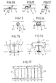
- the edges 5 of the elements have, at mid-thickness, a recess 6 so that an edge 7 having a thickness substantially equal to half the thickness of the element, extends beyond the entire outline of the element.
- the projecting edges 7 will come to bear against one another as shown in FIG. 10, which will ensure a connection of the elements or panels with each other.
- connection means L essentially formed by an assembly of ribs and grooves, may have shapes different from those shown in FIGS. 1 and 10.
- protruding elements such as 8 could be provided.
- FIG. 8 in the form of a “dovetail” intended to cooperate with corresponding recesses such as 9.
- Figure 9 shows another variant of connecting means which can be provided on the edge of the elements 4, and which is constituted by a sort of tongue 10 of circular shape, which is connected by a portion 11 narrowed at the edge of the panel.
- This tongue 10 is intended to cooperate with a corresponding recess, in the manner of the connecting means provided between the pieces of a puzzle.
- the part 7a projecting over the entire periphery of the covering element is limited by a convex-concave surface 12 suitable for cooperating with the convex-concave surface. of the adjacent element arranged upside down.
- FIG. 12 represents connection means L of the tenon type 13 provided on the edge of an element and mortise 14 provided on the edge of the adjacent element.
- connection means of the “dry” type male and female elements are combined (grooves or notches) either in the plane of the covering element (solution of FIGS. 8 and 9) either in section (solution of Figures 10 to 12).
- the connecting means L interlock with a keying by sealing product M, of the mortar, resin or other product type, between the elements 4a, 4b which have, on their edges, grooves or g, r grooves intended to receive this sealant.
- a strong inclusion such as steel bars, fibers, or the like can be provided in the sealant.
- the covering elements 4 or 4a, 4b are assembled “in situ” and are fixed to the end parts 3 of the sealed frames.
- the elements 4, 4a, 4b are put in place as the excavation E progresses. As visible from FIG. 1, the elements 4, 4a, 4b are put in place top to bottom.
- the assembled system is self-stable.
- the number of elements 4 that are fixed on the reinforcements 2 and therefore the number of sealed reinforcements 2 is at most equal to 1 ⁇ half of the total number of prefabricated elements.
- Drainage means D are arranged over the entire height of the excavation wall 1, between this wall 1 and the covering R.
- These drainage means D may be constituted, for example, by a draining curtain such as a sheet 16 of fibers, in particular a geotextile sheet unwound along the wall 1.
- a channel 17 provided with a drain 18 is provided at the bottom of this wall to collect drainage water.
- the drainage means D can be constituted by strainers (not shown) formed by plastic pipes provided with holes in their wall and arranged against the wall 1 while being inclined downwards.
- a stuffing B is injected.
- This stuffing can be formed by a thin mortar or by a swelling product, or even by sand.
- the stuffing B is put in place using holes existing in the elements (either anchoring holes or specific stuffing holes).
- the blocking elements 4 associated with these frames are locked on the sealed frames 2, this blocking being ensured by relatively moderate tightening of the screwed nuts. on the threaded ends of parts 3 of the armatures.
- the heads of the reinforcements and the nuts can be covered by a cover, for example made of concrete, so that the coating R has its finished appearance.
- Figures 15 and 16 show anchoring devices with a head in particular self-locking between adjacent elements.
- the edges 7 of the adjacent elements 4 are inclined substantially at 60 ° -70 ° relative to the mean plane of the element.
- the frame 2 passes between two adjacent edges.
- a self-blocking head T made of resistant material (metal, concrete, hard plastic), in the shape of a trunk of a pyramid or a truncated cone, whose wall matches that of the edges, acts like a wedge under the action of the anchoring force, this head T being retained by the nut d.
- the head T1 is formed by a sort of plate with projecting edges u engaged in the notches provided on the adjacent elements, with possibly self-locking effect.
- the frames 2 can be provided with an adjustable internal stopper w (for example metal plate) (FIGS. 15, 16), making it possible to correctly position the prefabricated elements.
- an adjustable internal stopper w for example metal plate
- the elements such as 15 (FIG. 6) intended to be fixed to the sealing reinforcements 2 comprise a reinforced zone 20, of greater thickness, in particular provided in the central region of said element and provided with a through hole for the frame 2.
- the prefabricated elements 4 can be identical or complementary.
- the coating R involves different coating elements.
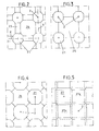
- elements 21 in the form of regular octagons fixed on the frames 2.
- the spaces 24 delimited by a contour formed by elements 21 and elements 22, 23 can be open or, possibly, provided with other elements or with own means to retain stuffing B, in the case where the space 24 has a large surface.
- FIG. 4 shows a variant according to which the elements 21 of octagonal shape, anchored on the frames 2, ensure the maintenance of other elements 26 of square shape of which one diagonal is substantially vertical and the other diagonal substantially horizontal.
- These prefabricated elements, of two different types, are coupled to each other in a determined order.
- FIG. 5 shows a coating obtained using identical elements 27 which are substantially square in shape but whose angles have been cut.
- An element 27, fixed to a frame 2 is arranged “front” while other elements 27a, adjacent to this element 27 are arranged “back” (in a manner similar to that shown in FIG. 1) to allow the attachment of the connecting means L, of the type shown in FIGS. 10 and 11, provided on the edges of these elements.
- FIG. 7 shows an embodiment in which the prefabricated elements 28 have a circular shape.
- One element in three, as in the case of FIG. 6, is fixed on a connecting frame 2, the distribution of the fixed elements among all the other elements being regular, as in the case of FIG. 6.
- the method of the invention allows a rapid coating of natural or artificial excavation walls, having interesting properties on the phonic level, in particular because of the nature of the surface, and on the aesthetic level.
- FIG. 17 shows a variant in which longitudinal elements 4f (vertical, horizontal, oblique) are fixed at several points, on several anchors 2, these longitudinal elements 4f serving to maintain transverse elements 4g ensuring the coating.
Claims (11)
Priority Applications (1)
| Application Number | Priority Date | Filing Date | Title |
|---|---|---|---|
| AT85401227T ATE47446T1 (de) | 1984-06-29 | 1985-06-19 | Vorgefertigte stuetzelemente zum schutz, verstaerken und/oder bekleiden von ausschachtungen, anker- und verbindungsvorrichtungen und verfahren zum anwenden dieser elemente und vorrichtungen. |
Applications Claiming Priority (2)
| Application Number | Priority Date | Filing Date | Title |
|---|---|---|---|
| FR8410336A FR2566814B1 (fr) | 1984-06-29 | 1984-06-29 | Elements prefabriques de soutenement pour la protection, le renforcement et/ou le revetement d'excavations, dispositifs d'ancrage et d'assemblage et procede de mise en oeuvre de ces elements et dispositifs |
| FR8410336 | 1984-06-29 |
Publications (3)
| Publication Number | Publication Date |
|---|---|
| EP0166656A2 EP0166656A2 (de) | 1986-01-02 |
| EP0166656A3 EP0166656A3 (en) | 1986-05-28 |
| EP0166656B1 true EP0166656B1 (de) | 1989-10-18 |
Family
ID=9305613
Family Applications (1)
| Application Number | Title | Priority Date | Filing Date |
|---|---|---|---|
| EP85401227A Expired EP0166656B1 (de) | 1984-06-29 | 1985-06-19 | Vorgefertigte Stützelemente zum Schutz, Verstärken und/oder Bekleiden von Ausschachtungen, Anker- und Verbindungsvorrichtungen und Verfahren zum Anwenden dieser Elemente und Vorrichtungen |
Country Status (7)
| Country | Link |
|---|---|
| US (1) | US4718792A (de) |
| EP (1) | EP0166656B1 (de) |
| JP (1) | JPS6114322A (de) |
| AT (1) | ATE47446T1 (de) |
| DE (1) | DE3573817D1 (de) |
| ES (1) | ES8801015A1 (de) |
| FR (1) | FR2566814B1 (de) |
Cited By (1)
| Publication number | Priority date | Publication date | Assignee | Title |
|---|---|---|---|---|
| DE4214078A1 (de) * | 1992-04-29 | 1993-11-04 | Linden Betonwerk Gmbh & Co | Bausystem fuer ein bepflanzbare boeschungssteine umfasssendes stuetzbauwerk |
Families Citing this family (25)
| Publication number | Priority date | Publication date | Assignee | Title |
|---|---|---|---|---|
| DE3716496C1 (en) * | 1987-05-16 | 1988-11-10 | Bilfinger Berger Bau | Sealing system for refuse landfills with sloping landfill delimitations |
| DE3802671A1 (de) * | 1988-01-29 | 1989-08-10 | Niederberg Chemie | Deponiestandort mit steilwaenden |
| DE3931316C2 (de) * | 1988-03-31 | 1999-02-11 | Hermann Dr Ing Lohmiller | Verfahren zur Herstellung einer Verbau- oder Stützwand für Geländeeinschnitte |
| FR2641295B1 (fr) * | 1989-01-03 | 1991-12-13 | Flourens Bruno | Procede et dispositif pour l'ancrage des ecailles de soutien d'un mur en terre armee |
| IT1237757B (it) * | 1989-11-10 | 1993-06-17 | Rios Giovanni Da | Pannello prefabbricato con supporto vegetativo, particolarmente per muri di sostegno |
| US5207038A (en) * | 1990-06-04 | 1993-05-04 | Yermiyahu Negri | Reinforced earth structures and method of construction thereof |
| JPH0587451U (ja) * | 1990-12-14 | 1993-11-26 | 株式会社ゼクセル | 建屋の局所冷暖房装置 |
| US5221157A (en) * | 1990-12-28 | 1993-06-22 | Prestedge Gordon K | Revetments and units for use in constructing revetments |
| US5158399A (en) * | 1991-12-27 | 1992-10-27 | Flores Raymond H | Method for erecting a below grade wall |
| ES2063685B1 (es) * | 1993-03-08 | 1995-06-16 | Abilla Alejandro Marsol | Material para revestimiento ecologico de taludes y procedimiento correspondiente. |
| GB2276899B (en) * | 1993-03-11 | 1995-12-20 | Cordek Ltd | Improvements in or relating to filling in a hollow in the ground |
| GB2284002A (en) * | 1993-11-19 | 1995-05-24 | George Hayes | A modular coastal protection system |
| US5395185A (en) * | 1993-11-22 | 1995-03-07 | Schnabel Foundation Company | Method of temporarily shoring and permanently facing and excavated slope with a retaining wall |
| US5551810A (en) * | 1994-06-08 | 1996-09-03 | Schnabel Foundation Company | Retaining wall with an outer face and method of forming the same |
| GB9417573D0 (en) * | 1994-09-01 | 1994-10-19 | Vidal Henri Brevets | Facing panel for earth structures |
| US5588784A (en) * | 1995-06-07 | 1996-12-31 | Schnabel Foundation Company | Soil or rock nail wall with outer face and method of constructing the same |
| US6167671B1 (en) | 1998-12-21 | 2001-01-02 | Steven D. Wilson | Prefabricated concrete wall form system |
| GB2351518B (en) * | 1999-07-01 | 2003-09-03 | Cordek Ltd | Improvements in or relating to facings for a ground slope and method of building such facings |
| GB2356003B (en) * | 1999-11-05 | 2003-10-01 | Rmc | Wall lining method and system |
| US20040007656A1 (en) * | 2002-07-12 | 2004-01-15 | George Seela | Reusable modular composite panel form system |
| US6874975B2 (en) * | 2002-12-09 | 2005-04-05 | Hilfiker Pipe Company | Soil-nail apparatus and method for constructing soil reinforced earthen retaining walls |
| US7828497B2 (en) * | 2007-09-18 | 2010-11-09 | Franklin Dale Boxberger | Construction and design method |
| US8523495B2 (en) * | 2009-06-01 | 2013-09-03 | Franklin R. Lacy | Bulkhead anchoring system for waterways |
| AT516826B1 (de) * | 2015-09-28 | 2016-09-15 | Swietelsky Baugesellschaft M B H | Vorrichtung zur Baugrubensicherung |
| CN113605402B (zh) * | 2021-07-26 | 2023-02-21 | 江苏银洲建设集团有限公司 | 一种深基坑支护止水系统及其施工方法 |
Family Cites Families (14)
| Publication number | Priority date | Publication date | Assignee | Title |
|---|---|---|---|---|
| US3198614A (en) * | 1962-02-26 | 1965-08-03 | Robert P Powell | Piling construction |
| US3464211A (en) * | 1967-03-08 | 1969-09-02 | Magne A Andresen | Modular structure for restraining walls |
| US3802204A (en) * | 1970-04-01 | 1974-04-09 | E Mason | Retaining wall and method for construction of the same |
| CH545892A (de) * | 1973-05-08 | 1974-02-15 | ||
| US3922864A (en) * | 1974-02-25 | 1975-12-02 | Hilfiker Pipe Co | Stringer for retaining wall construction |
| US4117686A (en) * | 1976-09-17 | 1978-10-03 | Hilfiker Pipe Co. | Fabric structures for earth retaining walls |
| CH621174A5 (en) * | 1977-07-07 | 1981-01-15 | Willi Steiner | Method of constructing a retaining wall and set of structural parts for carrying out this method |
| FR2415193A1 (fr) * | 1978-01-20 | 1979-08-17 | Louis Claude | Elements de soutenement pour ouvrages de travaux publics, tels que galeries, tunnels, puits, tranchees.. |
| JPS5567293A (en) * | 1978-11-15 | 1980-05-21 | Toshiba Corp | Horn type loudspeaker |
| FR2446376A1 (fr) * | 1979-01-15 | 1980-08-08 | Pont A Mousson | Procede et dispositif pour l'assemblage de voussoirs d'un revetement de tunnel |
| DE3042967A1 (de) * | 1980-11-04 | 1982-07-01 | Rudolf Nikolaus 8034 Germering Aumiller | Bepflanzbare, platzsparende hohlwand (laermschutzwand) |
| US4426176A (en) * | 1981-08-10 | 1984-01-17 | Tokuyama Soda Co., Ltd. | L-Shaped concrete block and method for constructing a retaining wall by such L-shaped concrete blocks |
| US4449857A (en) * | 1981-10-26 | 1984-05-22 | Vsl Corporation | Retained earth system with threaded connection between a retaining wall and soil reinforcement panels |
| JPS5938425A (ja) * | 1982-08-26 | 1984-03-02 | Makoto Kaneuji | 斜面切取工法 |
-
1984
- 1984-06-29 FR FR8410336A patent/FR2566814B1/fr not_active Expired
- 1984-12-25 JP JP59281888A patent/JPS6114322A/ja active Pending
-
1985
- 1985-06-19 AT AT85401227T patent/ATE47446T1/de not_active IP Right Cessation
- 1985-06-19 DE DE8585401227T patent/DE3573817D1/de not_active Expired
- 1985-06-19 EP EP85401227A patent/EP0166656B1/de not_active Expired
- 1985-06-28 ES ES545177A patent/ES8801015A1/es not_active Expired
-
1987
- 1987-02-12 US US07/014,170 patent/US4718792A/en not_active Expired - Fee Related
Cited By (1)
| Publication number | Priority date | Publication date | Assignee | Title |
|---|---|---|---|---|
| DE4214078A1 (de) * | 1992-04-29 | 1993-11-04 | Linden Betonwerk Gmbh & Co | Bausystem fuer ein bepflanzbare boeschungssteine umfasssendes stuetzbauwerk |
Also Published As
| Publication number | Publication date |
|---|---|
| ES8801015A1 (es) | 1987-12-01 |
| US4718792A (en) | 1988-01-12 |
| EP0166656A2 (de) | 1986-01-02 |
| FR2566814B1 (fr) | 1986-10-17 |
| ATE47446T1 (de) | 1989-11-15 |
| DE3573817D1 (en) | 1989-11-23 |
| JPS6114322A (ja) | 1986-01-22 |
| FR2566814A1 (fr) | 1986-01-03 |
| ES545177A0 (es) | 1987-12-01 |
| EP0166656A3 (en) | 1986-05-28 |
Similar Documents
| Publication | Publication Date | Title |
|---|---|---|
| EP0166656B1 (de) | Vorgefertigte Stützelemente zum Schutz, Verstärken und/oder Bekleiden von Ausschachtungen, Anker- und Verbindungsvorrichtungen und Verfahren zum Anwenden dieser Elemente und Vorrichtungen | |
| CA1302111C (fr) | Procede et appareillage pour la realisation d'une dalle rigide permettant de porter une construction | |
| CA1319261C (fr) | Structures cellulaires pour murs de soutenement | |
| EP0060230A1 (de) | Tragkonstruktion aus einem Konglomerat oder armiertem Beton, insbesondere gegen Erdbeben, für ebene sowie gewölbte oder bogenförmige Konstruktionen, hergestellt aus Modul-Elementen | |
| EP0244890B2 (de) | Verfahren zur Herstellung von hohlen Elementen, wie etwa Leitungen, Silos oder Bunker und Elemente, hergestellt durch dieses Verfahren | |
| EP0381547B1 (de) | Verfahren zur Herstellung einer vergrabenen Leitung | |
| FR2557200A1 (fr) | Dispositif de soutenement souple des parois de galeries souterraines | |
| FR2631397A1 (fr) | Procede d'assemblage d'un element en beton et d'un support et structure correspondante | |
| FR2876716A1 (fr) | Dispositif pour la realisation d'une barriere etanche anti-crue | |
| FR2613394A1 (fr) | Parois etanches pour ouvrages hydrauliques en beton compact et procede de construction de celles-ci | |
| FR2465032A1 (fr) | Perfectionnement aux murs de soutenement | |
| FR2631358A1 (fr) | Construction de soutenement pour stabiliser le sol | |
| CH434335A (fr) | Procédé de construction d'un passage sous voie et installation pour la mise en oeuvre de ce procédé | |
| FR2488302A1 (fr) | Jeu d'elements de construction pour eriger des murs de soutenement | |
| EP0004998A2 (de) | Baustruktur | |
| FR2824851A1 (fr) | Appui de pont prefabrique | |
| FR2619401A1 (fr) | Elements prefabriques pour la construction de murs et parois | |
| FR2509771A1 (fr) | Ensemble d'elements prefabriques pour l'erection d'un mur-caisson a poutres et mur-caisson obtenu | |
| FR2543202A1 (fr) | Piscine realisee par assemblage d'elements prefabriques en beton | |
| KR100830310B1 (ko) | 토류판용 중공 판넬 | |
| FR2807456A1 (fr) | Dispositif de soutenement et/ou de stabilisation de mur, merlon, talus | |
| FR2994702A1 (fr) | Module de paroi laterale, notamment de bassin ou de mur routier ou de cloture, ensemble de tels modules et bassin comportant de tels modules | |
| FR2610339A1 (fr) | Procede de realisation de soubassements d'immeubles et moyens pour mettre en oeuvre ledit procede | |
| FR2486563A2 (fr) | Element prefabrique pour l'erection d'un mur-caisson et murs obtenus | |
| EP0395534A1 (de) | Gebäudekonstruktion |
Legal Events
| Date | Code | Title | Description |
|---|---|---|---|
| PUAI | Public reference made under article 153(3) epc to a published international application that has entered the european phase |
Free format text: ORIGINAL CODE: 0009012 |
|
| AK | Designated contracting states |
Designated state(s): AT BE CH DE GB IT LI NL SE |
|
| PUAL | Search report despatched |
Free format text: ORIGINAL CODE: 0009013 |
|
| AK | Designated contracting states |
Kind code of ref document: A3 Designated state(s): AT BE CH DE GB IT LI NL SE |
|
| 17P | Request for examination filed |
Effective date: 19861114 |
|
| 17Q | First examination report despatched |
Effective date: 19880422 |
|
| GRAA | (expected) grant |
Free format text: ORIGINAL CODE: 0009210 |
|
| AK | Designated contracting states |
Kind code of ref document: B1 Designated state(s): AT BE CH DE GB IT LI NL SE |
|
| PG25 | Lapsed in a contracting state [announced via postgrant information from national office to epo] |
Ref country code: SE Effective date: 19891018 Ref country code: NL Effective date: 19891018 Ref country code: AT Effective date: 19891018 |
|
| REF | Corresponds to: |
Ref document number: 47446 Country of ref document: AT Date of ref document: 19891115 Kind code of ref document: T |
|
| REF | Corresponds to: |
Ref document number: 3573817 Country of ref document: DE Date of ref document: 19891123 |
|
| GBT | Gb: translation of ep patent filed (gb section 77(6)(a)/1977) | ||
| ITF | It: translation for a ep patent filed |
Owner name: JACOBACCI & PERANI S.P.A. |
|
| NLV1 | Nl: lapsed or annulled due to failure to fulfill the requirements of art. 29p and 29m of the patents act | ||
| PLBE | No opposition filed within time limit |
Free format text: ORIGINAL CODE: 0009261 |
|
| STAA | Information on the status of an ep patent application or granted ep patent |
Free format text: STATUS: NO OPPOSITION FILED WITHIN TIME LIMIT |
|
| 26N | No opposition filed | ||
| PGFP | Annual fee paid to national office [announced via postgrant information from national office to epo] |
Ref country code: GB Payment date: 19930611 Year of fee payment: 9 |
|
| PGFP | Annual fee paid to national office [announced via postgrant information from national office to epo] |
Ref country code: CH Payment date: 19930617 Year of fee payment: 9 |
|
| ITTA | It: last paid annual fee | ||
| PGFP | Annual fee paid to national office [announced via postgrant information from national office to epo] |
Ref country code: BE Payment date: 19930709 Year of fee payment: 9 |
|
| PGFP | Annual fee paid to national office [announced via postgrant information from national office to epo] |
Ref country code: DE Payment date: 19930713 Year of fee payment: 9 |
|
| PG25 | Lapsed in a contracting state [announced via postgrant information from national office to epo] |
Ref country code: GB Effective date: 19940619 |
|
| PG25 | Lapsed in a contracting state [announced via postgrant information from national office to epo] |
Ref country code: LI Effective date: 19940630 Ref country code: CH Effective date: 19940630 Ref country code: BE Effective date: 19940630 |
|
| BERE | Be: lapsed |
Owner name: LOUIS CLAUDE Effective date: 19940630 |
|
| GBPC | Gb: european patent ceased through non-payment of renewal fee |
Effective date: 19940619 |
|
| REG | Reference to a national code |
Ref country code: CH Ref legal event code: PL |
|
| PG25 | Lapsed in a contracting state [announced via postgrant information from national office to epo] |
Ref country code: DE Effective date: 19950301 |