EP0325828B1 - Method of producing molding members - Google Patents
Method of producing molding members Download PDFInfo
- Publication number
- EP0325828B1 EP0325828B1 EP88303433A EP88303433A EP0325828B1 EP 0325828 B1 EP0325828 B1 EP 0325828B1 EP 88303433 A EP88303433 A EP 88303433A EP 88303433 A EP88303433 A EP 88303433A EP 0325828 B1 EP0325828 B1 EP 0325828B1
- Authority
- EP
- European Patent Office
- Prior art keywords
- molding member
- synthetic resin
- resin material
- section
- continuous body
- Prior art date
- Legal status (The legal status is an assumption and is not a legal conclusion. Google has not performed a legal analysis and makes no representation as to the accuracy of the status listed.)
- Expired - Lifetime
Links
Images


Classifications
-
- B—PERFORMING OPERATIONS; TRANSPORTING
- B60—VEHICLES IN GENERAL
- B60J—WINDOWS, WINDSCREENS, NON-FIXED ROOFS, DOORS, OR SIMILAR DEVICES FOR VEHICLES; REMOVABLE EXTERNAL PROTECTIVE COVERINGS SPECIALLY ADAPTED FOR VEHICLES
- B60J1/00—Windows; Windscreens; Accessories therefor
- B60J1/20—Accessories, e.g. wind deflectors, blinds
- B60J1/2002—Wind deflectors specially adapted for preventing soiling, e.g. for side windows
-
- B—PERFORMING OPERATIONS; TRANSPORTING
- B26—HAND CUTTING TOOLS; CUTTING; SEVERING
- B26D—CUTTING; DETAILS COMMON TO MACHINES FOR PERFORATING, PUNCHING, CUTTING-OUT, STAMPING-OUT OR SEVERING
- B26D1/00—Cutting through work characterised by the nature or movement of the cutting member or particular materials not otherwise provided for; Apparatus or machines therefor; Cutting members therefor
- B26D1/01—Cutting through work characterised by the nature or movement of the cutting member or particular materials not otherwise provided for; Apparatus or machines therefor; Cutting members therefor involving a cutting member which does not travel with the work
- B26D1/02—Cutting through work characterised by the nature or movement of the cutting member or particular materials not otherwise provided for; Apparatus or machines therefor; Cutting members therefor involving a cutting member which does not travel with the work having a stationary cutting member
-
- B—PERFORMING OPERATIONS; TRANSPORTING
- B26—HAND CUTTING TOOLS; CUTTING; SEVERING
- B26D—CUTTING; DETAILS COMMON TO MACHINES FOR PERFORATING, PUNCHING, CUTTING-OUT, STAMPING-OUT OR SEVERING
- B26D1/00—Cutting through work characterised by the nature or movement of the cutting member or particular materials not otherwise provided for; Apparatus or machines therefor; Cutting members therefor
- B26D1/01—Cutting through work characterised by the nature or movement of the cutting member or particular materials not otherwise provided for; Apparatus or machines therefor; Cutting members therefor involving a cutting member which does not travel with the work
- B26D1/12—Cutting through work characterised by the nature or movement of the cutting member or particular materials not otherwise provided for; Apparatus or machines therefor; Cutting members therefor involving a cutting member which does not travel with the work having a cutting member moving about an axis
- B26D1/14—Cutting through work characterised by the nature or movement of the cutting member or particular materials not otherwise provided for; Apparatus or machines therefor; Cutting members therefor involving a cutting member which does not travel with the work having a cutting member moving about an axis with a circular cutting member, e.g. disc cutter
- B26D1/20—Cutting through work characterised by the nature or movement of the cutting member or particular materials not otherwise provided for; Apparatus or machines therefor; Cutting members therefor involving a cutting member which does not travel with the work having a cutting member moving about an axis with a circular cutting member, e.g. disc cutter coacting with a fixed member
-
- B—PERFORMING OPERATIONS; TRANSPORTING
- B26—HAND CUTTING TOOLS; CUTTING; SEVERING
- B26D—CUTTING; DETAILS COMMON TO MACHINES FOR PERFORATING, PUNCHING, CUTTING-OUT, STAMPING-OUT OR SEVERING
- B26D3/00—Cutting work characterised by the nature of the cut made; Apparatus therefor
- B26D3/28—Splitting layers from work; Mutually separating layers by cutting
-
- B—PERFORMING OPERATIONS; TRANSPORTING
- B29—WORKING OF PLASTICS; WORKING OF SUBSTANCES IN A PLASTIC STATE IN GENERAL
- B29C—SHAPING OR JOINING OF PLASTICS; SHAPING OF MATERIAL IN A PLASTIC STATE, NOT OTHERWISE PROVIDED FOR; AFTER-TREATMENT OF THE SHAPED PRODUCTS, e.g. REPAIRING
- B29C48/00—Extrusion moulding, i.e. expressing the moulding material through a die or nozzle which imparts the desired form; Apparatus therefor
- B29C48/001—Combinations of extrusion moulding with other shaping operations
- B29C48/0019—Combinations of extrusion moulding with other shaping operations combined with shaping by flattening, folding or bending
-
- B—PERFORMING OPERATIONS; TRANSPORTING
- B29—WORKING OF PLASTICS; WORKING OF SUBSTANCES IN A PLASTIC STATE IN GENERAL
- B29C—SHAPING OR JOINING OF PLASTICS; SHAPING OF MATERIAL IN A PLASTIC STATE, NOT OTHERWISE PROVIDED FOR; AFTER-TREATMENT OF THE SHAPED PRODUCTS, e.g. REPAIRING
- B29C48/00—Extrusion moulding, i.e. expressing the moulding material through a die or nozzle which imparts the desired form; Apparatus therefor
- B29C48/001—Combinations of extrusion moulding with other shaping operations
- B29C48/0022—Combinations of extrusion moulding with other shaping operations combined with cutting
-
- B—PERFORMING OPERATIONS; TRANSPORTING
- B29—WORKING OF PLASTICS; WORKING OF SUBSTANCES IN A PLASTIC STATE IN GENERAL
- B29C—SHAPING OR JOINING OF PLASTICS; SHAPING OF MATERIAL IN A PLASTIC STATE, NOT OTHERWISE PROVIDED FOR; AFTER-TREATMENT OF THE SHAPED PRODUCTS, e.g. REPAIRING
- B29C48/00—Extrusion moulding, i.e. expressing the moulding material through a die or nozzle which imparts the desired form; Apparatus therefor
- B29C48/03—Extrusion moulding, i.e. expressing the moulding material through a die or nozzle which imparts the desired form; Apparatus therefor characterised by the shape of the extruded material at extrusion
- B29C48/12—Articles with an irregular circumference when viewed in cross-section, e.g. window profiles
-
- B—PERFORMING OPERATIONS; TRANSPORTING
- B29—WORKING OF PLASTICS; WORKING OF SUBSTANCES IN A PLASTIC STATE IN GENERAL
- B29C—SHAPING OR JOINING OF PLASTICS; SHAPING OF MATERIAL IN A PLASTIC STATE, NOT OTHERWISE PROVIDED FOR; AFTER-TREATMENT OF THE SHAPED PRODUCTS, e.g. REPAIRING
- B29C48/00—Extrusion moulding, i.e. expressing the moulding material through a die or nozzle which imparts the desired form; Apparatus therefor
- B29C48/15—Extrusion moulding, i.e. expressing the moulding material through a die or nozzle which imparts the desired form; Apparatus therefor incorporating preformed parts or layers, e.g. extrusion moulding around inserts
- B29C48/154—Coating solid articles, i.e. non-hollow articles
- B29C48/155—Partial coating thereof
-
- B—PERFORMING OPERATIONS; TRANSPORTING
- B29—WORKING OF PLASTICS; WORKING OF SUBSTANCES IN A PLASTIC STATE IN GENERAL
- B29C—SHAPING OR JOINING OF PLASTICS; SHAPING OF MATERIAL IN A PLASTIC STATE, NOT OTHERWISE PROVIDED FOR; AFTER-TREATMENT OF THE SHAPED PRODUCTS, e.g. REPAIRING
- B29C48/00—Extrusion moulding, i.e. expressing the moulding material through a die or nozzle which imparts the desired form; Apparatus therefor
- B29C48/25—Component parts, details or accessories; Auxiliary operations
- B29C48/30—Extrusion nozzles or dies
- B29C48/302—Extrusion nozzles or dies being adjustable, i.e. having adjustable exit sections
-
- B—PERFORMING OPERATIONS; TRANSPORTING
- B29—WORKING OF PLASTICS; WORKING OF SUBSTANCES IN A PLASTIC STATE IN GENERAL
- B29C—SHAPING OR JOINING OF PLASTICS; SHAPING OF MATERIAL IN A PLASTIC STATE, NOT OTHERWISE PROVIDED FOR; AFTER-TREATMENT OF THE SHAPED PRODUCTS, e.g. REPAIRING
- B29C48/00—Extrusion moulding, i.e. expressing the moulding material through a die or nozzle which imparts the desired form; Apparatus therefor
- B29C48/25—Component parts, details or accessories; Auxiliary operations
- B29C48/92—Measuring, controlling or regulating
-
- B—PERFORMING OPERATIONS; TRANSPORTING
- B29—WORKING OF PLASTICS; WORKING OF SUBSTANCES IN A PLASTIC STATE IN GENERAL
- B29C—SHAPING OR JOINING OF PLASTICS; SHAPING OF MATERIAL IN A PLASTIC STATE, NOT OTHERWISE PROVIDED FOR; AFTER-TREATMENT OF THE SHAPED PRODUCTS, e.g. REPAIRING
- B29C67/00—Shaping techniques not covered by groups B29C39/00 - B29C65/00, B29C70/00 or B29C73/00
- B29C67/0044—Shaping techniques not covered by groups B29C39/00 - B29C65/00, B29C70/00 or B29C73/00 for shaping edges or extremities
-
- B—PERFORMING OPERATIONS; TRANSPORTING
- B60—VEHICLES IN GENERAL
- B60J—WINDOWS, WINDSCREENS, NON-FIXED ROOFS, DOORS, OR SIMILAR DEVICES FOR VEHICLES; REMOVABLE EXTERNAL PROTECTIVE COVERINGS SPECIALLY ADAPTED FOR VEHICLES
- B60J1/00—Windows; Windscreens; Accessories therefor
- B60J1/02—Windows; Windscreens; Accessories therefor arranged at the vehicle front, e.g. structure of the glazing, mounting of the glazing
-
- B—PERFORMING OPERATIONS; TRANSPORTING
- B60—VEHICLES IN GENERAL
- B60J—WINDOWS, WINDSCREENS, NON-FIXED ROOFS, DOORS, OR SIMILAR DEVICES FOR VEHICLES; REMOVABLE EXTERNAL PROTECTIVE COVERINGS SPECIALLY ADAPTED FOR VEHICLES
- B60J10/00—Sealing arrangements
- B60J10/15—Sealing arrangements characterised by the material
- B60J10/18—Sealing arrangements characterised by the material provided with reinforcements or inserts
-
- B—PERFORMING OPERATIONS; TRANSPORTING
- B60—VEHICLES IN GENERAL
- B60J—WINDOWS, WINDSCREENS, NON-FIXED ROOFS, DOORS, OR SIMILAR DEVICES FOR VEHICLES; REMOVABLE EXTERNAL PROTECTIVE COVERINGS SPECIALLY ADAPTED FOR VEHICLES
- B60J10/00—Sealing arrangements
- B60J10/20—Sealing arrangements characterised by the shape
- B60J10/21—Sealing arrangements characterised by the shape having corner parts or bends
-
- B—PERFORMING OPERATIONS; TRANSPORTING
- B60—VEHICLES IN GENERAL
- B60J—WINDOWS, WINDSCREENS, NON-FIXED ROOFS, DOORS, OR SIMILAR DEVICES FOR VEHICLES; REMOVABLE EXTERNAL PROTECTIVE COVERINGS SPECIALLY ADAPTED FOR VEHICLES
- B60J10/00—Sealing arrangements
- B60J10/20—Sealing arrangements characterised by the shape
- B60J10/22—Sealing arrangements characterised by the shape having varying cross-section in the longitudinal direction
-
- B—PERFORMING OPERATIONS; TRANSPORTING
- B60—VEHICLES IN GENERAL
- B60J—WINDOWS, WINDSCREENS, NON-FIXED ROOFS, DOORS, OR SIMILAR DEVICES FOR VEHICLES; REMOVABLE EXTERNAL PROTECTIVE COVERINGS SPECIALLY ADAPTED FOR VEHICLES
- B60J10/00—Sealing arrangements
- B60J10/20—Sealing arrangements characterised by the shape
- B60J10/25—Sealing arrangements characterised by the shape characterised by water drainage means
-
- B—PERFORMING OPERATIONS; TRANSPORTING
- B60—VEHICLES IN GENERAL
- B60J—WINDOWS, WINDSCREENS, NON-FIXED ROOFS, DOORS, OR SIMILAR DEVICES FOR VEHICLES; REMOVABLE EXTERNAL PROTECTIVE COVERINGS SPECIALLY ADAPTED FOR VEHICLES
- B60J10/00—Sealing arrangements
- B60J10/20—Sealing arrangements characterised by the shape
- B60J10/26—Sealing arrangements characterised by the shape characterised by the surface shape
- B60J10/265—Sealing arrangements characterised by the shape characterised by the surface shape the surface being primarily decorative
-
- B—PERFORMING OPERATIONS; TRANSPORTING
- B60—VEHICLES IN GENERAL
- B60J—WINDOWS, WINDSCREENS, NON-FIXED ROOFS, DOORS, OR SIMILAR DEVICES FOR VEHICLES; REMOVABLE EXTERNAL PROTECTIVE COVERINGS SPECIALLY ADAPTED FOR VEHICLES
- B60J10/00—Sealing arrangements
- B60J10/70—Sealing arrangements specially adapted for windows or windscreens
-
- B—PERFORMING OPERATIONS; TRANSPORTING
- B60—VEHICLES IN GENERAL
- B60J—WINDOWS, WINDSCREENS, NON-FIXED ROOFS, DOORS, OR SIMILAR DEVICES FOR VEHICLES; REMOVABLE EXTERNAL PROTECTIVE COVERINGS SPECIALLY ADAPTED FOR VEHICLES
- B60J10/00—Sealing arrangements
- B60J10/80—Sealing arrangements specially adapted for opening panels, e.g. doors
-
- B—PERFORMING OPERATIONS; TRANSPORTING
- B60—VEHICLES IN GENERAL
- B60R—VEHICLES, VEHICLE FITTINGS, OR VEHICLE PARTS, NOT OTHERWISE PROVIDED FOR
- B60R13/00—Elements for body-finishing, identifying, or decorating; Arrangements or adaptations for advertising purposes
- B60R13/07—Water drainage or guide means not integral with roof structure
-
- B—PERFORMING OPERATIONS; TRANSPORTING
- B29—WORKING OF PLASTICS; WORKING OF SUBSTANCES IN A PLASTIC STATE IN GENERAL
- B29C—SHAPING OR JOINING OF PLASTICS; SHAPING OF MATERIAL IN A PLASTIC STATE, NOT OTHERWISE PROVIDED FOR; AFTER-TREATMENT OF THE SHAPED PRODUCTS, e.g. REPAIRING
- B29C2793/00—Shaping techniques involving a cutting or machining operation
- B29C2793/0027—Cutting off
-
- B—PERFORMING OPERATIONS; TRANSPORTING
- B29—WORKING OF PLASTICS; WORKING OF SUBSTANCES IN A PLASTIC STATE IN GENERAL
- B29C—SHAPING OR JOINING OF PLASTICS; SHAPING OF MATERIAL IN A PLASTIC STATE, NOT OTHERWISE PROVIDED FOR; AFTER-TREATMENT OF THE SHAPED PRODUCTS, e.g. REPAIRING
- B29C2793/00—Shaping techniques involving a cutting or machining operation
- B29C2793/0063—Cutting longitudinally
-
- B—PERFORMING OPERATIONS; TRANSPORTING
- B29—WORKING OF PLASTICS; WORKING OF SUBSTANCES IN A PLASTIC STATE IN GENERAL
- B29C—SHAPING OR JOINING OF PLASTICS; SHAPING OF MATERIAL IN A PLASTIC STATE, NOT OTHERWISE PROVIDED FOR; AFTER-TREATMENT OF THE SHAPED PRODUCTS, e.g. REPAIRING
- B29C2948/00—Indexing scheme relating to extrusion moulding
- B29C2948/92—Measuring, controlling or regulating
- B29C2948/92504—Controlled parameter
- B29C2948/92609—Dimensions
- B29C2948/92638—Length
-
- B—PERFORMING OPERATIONS; TRANSPORTING
- B29—WORKING OF PLASTICS; WORKING OF SUBSTANCES IN A PLASTIC STATE IN GENERAL
- B29C—SHAPING OR JOINING OF PLASTICS; SHAPING OF MATERIAL IN A PLASTIC STATE, NOT OTHERWISE PROVIDED FOR; AFTER-TREATMENT OF THE SHAPED PRODUCTS, e.g. REPAIRING
- B29C2948/00—Indexing scheme relating to extrusion moulding
- B29C2948/92—Measuring, controlling or regulating
- B29C2948/92819—Location or phase of control
- B29C2948/92933—Conveying, transporting or storage of articles
-
- B—PERFORMING OPERATIONS; TRANSPORTING
- B29—WORKING OF PLASTICS; WORKING OF SUBSTANCES IN A PLASTIC STATE IN GENERAL
- B29C—SHAPING OR JOINING OF PLASTICS; SHAPING OF MATERIAL IN A PLASTIC STATE, NOT OTHERWISE PROVIDED FOR; AFTER-TREATMENT OF THE SHAPED PRODUCTS, e.g. REPAIRING
- B29C48/00—Extrusion moulding, i.e. expressing the moulding material through a die or nozzle which imparts the desired form; Apparatus therefor
- B29C48/001—Combinations of extrusion moulding with other shaping operations
-
- B—PERFORMING OPERATIONS; TRANSPORTING
- B29—WORKING OF PLASTICS; WORKING OF SUBSTANCES IN A PLASTIC STATE IN GENERAL
- B29C—SHAPING OR JOINING OF PLASTICS; SHAPING OF MATERIAL IN A PLASTIC STATE, NOT OTHERWISE PROVIDED FOR; AFTER-TREATMENT OF THE SHAPED PRODUCTS, e.g. REPAIRING
- B29C48/00—Extrusion moulding, i.e. expressing the moulding material through a die or nozzle which imparts the desired form; Apparatus therefor
- B29C48/03—Extrusion moulding, i.e. expressing the moulding material through a die or nozzle which imparts the desired form; Apparatus therefor characterised by the shape of the extruded material at extrusion
- B29C48/06—Rod-shaped
-
- B—PERFORMING OPERATIONS; TRANSPORTING
- B29—WORKING OF PLASTICS; WORKING OF SUBSTANCES IN A PLASTIC STATE IN GENERAL
- B29C—SHAPING OR JOINING OF PLASTICS; SHAPING OF MATERIAL IN A PLASTIC STATE, NOT OTHERWISE PROVIDED FOR; AFTER-TREATMENT OF THE SHAPED PRODUCTS, e.g. REPAIRING
- B29C48/00—Extrusion moulding, i.e. expressing the moulding material through a die or nozzle which imparts the desired form; Apparatus therefor
- B29C48/03—Extrusion moulding, i.e. expressing the moulding material through a die or nozzle which imparts the desired form; Apparatus therefor characterised by the shape of the extruded material at extrusion
- B29C48/13—Articles with a cross-section varying in the longitudinal direction, e.g. corrugated pipes
-
- B—PERFORMING OPERATIONS; TRANSPORTING
- B29—WORKING OF PLASTICS; WORKING OF SUBSTANCES IN A PLASTIC STATE IN GENERAL
- B29L—INDEXING SCHEME ASSOCIATED WITH SUBCLASS B29C, RELATING TO PARTICULAR ARTICLES
- B29L2007/00—Flat articles, e.g. films or sheets
- B29L2007/007—Narrow strips, e.g. ribbons, tapes, bands
-
- B—PERFORMING OPERATIONS; TRANSPORTING
- B29—WORKING OF PLASTICS; WORKING OF SUBSTANCES IN A PLASTIC STATE IN GENERAL
- B29L—INDEXING SCHEME ASSOCIATED WITH SUBCLASS B29C, RELATING TO PARTICULAR ARTICLES
- B29L2031/00—Other particular articles
- B29L2031/30—Vehicles, e.g. ships or aircraft, or body parts thereof
- B29L2031/3005—Body finishings
- B29L2031/302—Trim strips
-
- Y—GENERAL TAGGING OF NEW TECHNOLOGICAL DEVELOPMENTS; GENERAL TAGGING OF CROSS-SECTIONAL TECHNOLOGIES SPANNING OVER SEVERAL SECTIONS OF THE IPC; TECHNICAL SUBJECTS COVERED BY FORMER USPC CROSS-REFERENCE ART COLLECTIONS [XRACs] AND DIGESTS
- Y10—TECHNICAL SUBJECTS COVERED BY FORMER USPC
- Y10T—TECHNICAL SUBJECTS COVERED BY FORMER US CLASSIFICATION
- Y10T428/00—Stock material or miscellaneous articles
- Y10T428/24—Structurally defined web or sheet [e.g., overall dimension, etc.]
- Y10T428/2419—Fold at edge
- Y10T428/24198—Channel-shaped edge component [e.g., binding, etc.]
Definitions
- the present invention relates to a method of producing molding members, for instance for automobiles, formed at least partly of a synthetic resin material.
- An automobile employs various kinds of elongate molding members formed at least partly of a synthetic resin material, such as drip molding members, front and rear window molding members, etc.
- the drip molding member extends along the front pillar and the side edge of the roof panel of the vehicle body
- front and rear window molding members extend respectively along the periphery of the front and rear window plates, i.e. along the front and rear pillars and the front and rear edges of the roof panel.
- a variety of requirements are imposed on the molding members, mainly from design and/or functional viewpoint, and resulted in an increased demand in the automobile industry for the molding members whose cross-sectional shape varies in the longitudinal direction.
- one proposal is directed to a window molding member having side portions with a first predetermined cross-sectional shape, an upper portion with a second predetermined cross-sectional shape, and corner portions arranged between the side and upper portions, where the cross-sectional shape changes gradually from the first to the second.
- a drip molding member composed of a core element in the form of a metal strip which has been shaped into the desired cross-sectional shape, as well as upper and lower lip elements of synthetic resin material which are integral with the core element and molded such that the core element is partly exposed to, and visible from outside as a longitudinally extending ornamental portion with a metallic luster.
- the lower lip element is of a cross-sectional shape that is substantially constant throughout the entire length, while the upper lip element has a pillar portion with a relatively wide first cross-sectional shape, a roof portion with a relatively narrow second cross-sectional shape, and a corner portion between the pillar and roof portions, where the cross-sectional shape changes gradually from the first to the second.
- each molding member Another possibility for the production of such molding members is to physically divide each molding member into first and second extruded portions with the respectively predetermined cross-sectional shapes, which are connected with each other either by an injection molding process or by using a separate connection piece.
- connection of the two portions by means of the injection molding accompanies formation of undesirable burrs along the junctions and resultant deterioration in the appearance, while use of the separate connection piece results in the increased number of the required components and assembly steps.
- GB-A-2126151 shows a process in which a molding member having a lip portion is cut in a predetermined pattern by engagement with a cutter movable laterally to the member.
- the preamble of claim 1 is based on this disclosure.
- EP 118397 shows a device for extruding a molding member with a lip portion. This lip is immediately following the extrusion step, selectively permanently deflected from its extruded shape.
- a method of producing a molding member for instance for a front or rear window for an automobile which includes, viewed in cross-section, a main body adapted to cover a gap formed between a window plate and an automobile body panel, a lip section projecting from said main body and adapted to cover the outer periphery of said window plate, the molding member being formed at least partly of a synthetic resin and the method including the steps of extruding the synthetic resin material into an elongate continuous body with a substantially constant cross-section throughout the length thereof; and removing from a predetermined location of said continuous body a controlled amount of the synthetic resin material, synchronously with the extrusion of the synthetic resin material, such that the cross-section of said continuous body varies in the longitudinal direction thereof, characterised in that said main body further comprises a ridge section projecting from the lip section for preventing flow of water across said ridge section, and in that said controlled amount of the synthetic resin material is removed from that portion of said continuous body which corresponds to said ridge section of said
- the longitudinally variable cross-sectional shape of the molding member can be readily obtained essentially based on extrusion molding technology, simply by removing a controlled amount of the synthetic resin material from a predetermined location of the continuous body after it has been extruded, and by subsequently cutting the continuous body into a predetermined length of the molding member.
- all the process steps can be carried out continuously, as contrasted with the conventional injection molding method, so that it is possible to produce the molding members with the desired, longitudinally variable cross-sectional shape, by means of a compact arrangement of the facility, and with a markedly improved productivity.
- connection of separately extruded portions of a molding member is not necessary, so that the present invention does not require the assembly of a plurality of components when producing a molding member, and preserves an excellent appearance of the product in an advantageous manner.
- FIG. 1 an automobile designated as a whole by reference numeral 1, which is provided with various kinds of elongate molding members composed at least partly of a suitable synthetic resin material.
- These molding member include, among others, a front window molding member 2, a drip molding member 3, etc., and the present invention is applicable to produce these elongate molding members with an improved productivity, as will be fully explained hereinafter.
- the front window molding member 2 is arranged along the periphery of side or the windshield plate, and includes a pair of side or pillar portions 2a extending along the front pillars of the automobile 1, respectively, an upper or roof portion 2b extending along the front edge of the roof panel of the automobile 1, and a pair of corner portions 2c arranged between the pillar portions 2a and that roof portion 2b.
- Each pillar portion 2a has a predetermined first cross-sectional shape which is substantially constant throughout the entire length of that portion 2a.
- the roof portion 2b has a predetermined second cross-sectional shape which is substantially constant throughout the entire length of that portion 2b, but which is different from that of the pillar portion 2a. Consequently, the shape of the pillar portion 2a gradually changes to that of the roof portion 2b in each corner portion 2c, or in its neighbourhood.
- the drip molding member 3 is arranged along the front pillar and the side edge of the roof panel of the automobile.
- molding members, 2,3 can be produced in the manner to be described hereinafter. Just for the sake of convenience, the following description will be made with reference to the production of the drip molding member 3.
- FIG. 2 a system diagram of the production line for carrying out the method according to the present invention.
- the production line includes an uncoiler 11 from which a metal strip 12 is continuously supplied by a pair of pinch rollers 13.
- Another roller 14 serves to continuously supply a protective tape 15 which is separably adhered, by means of a pair of adhesion rollers 16, onto that portion of the metal strip 12 which eventually forms ornamental portions 5 of the molding member 3 with the desired metallic luster, and which has thus to be protected by the tape 15.
- the metal strip 12 applied with the protective tape 15 forms a composite body 17 which, subsequently, is subjected to surface degreasing and cleaning at a cleaning station 18 for carrying out a sanding or the like treatment, is coated with an adhesive material at a roll coating station 19, and is subjected to baking at the baking station 20.
- the composite body 17 is further passed through and cooled in a cooling tank 21, and is then shaped into a desired, longitudinally constant cross-section at a roll forming machine 22 to form a continuous core element 4 of the molding member 3.
- the core element 4 so obtained is supplied to a measuring station 23 which includes a rotary encoder or the like detector for measuring the supplied length of the core element 4, and then to an extrusion die 24 which is further supplied with a suitable synthetic resin material in its heated molten state.
- the molten synthetic resin material is co-extruded from the extrusion die 24 as a continuous extruded body 25 in which the upper and lower lip elements 6, 7 are made integral with the core element 4, whereby the extruded body 25 has a substantially constant cross-section which corresponds to that of the pillar portion 3a of the molding member 3.
- the extruded body 25 as extruded from the extrusion die 24 is further subjected to the removal of a controlled amount of synthetic resin material from the predetermined location of the upper lip element 6.
- a controller 26 which is adapted to receive from the measuring station 23 a signal representing the supplied length of the core element 4, while a first cutting station 27 is arranged on the exit or discharge side of the die 24 and is adapted to be controlled by the controller 26 according to the supplied length of the core element 4.
- the extruded body 25 is subsequently passed through a cooling tank 28 where it is cooled, and is then advanced by a take-up device 29 and cut into the predetermined length of the product at a second cutting station 30 which, too, is controlled by the controller 26 according to the supplied length of the core element 4.
- the removal of the synthetic resin material is carried out while the extruded body 25 is still hot and soft.
- the extruded body 25 subjected to the removal of the synthetic resin material at the first cutting station 27 is then supplied to the second cutting station 30 where it is cut into the predetermined length of the desired molding member 3 at predetermined positions of the extruded body 25 which correspond to the centers of the length 2L1 and 2L3, respectively.
- the molding members can be continuously produced one by one, in an efficient and reliable manner.
- the molding member to be produced is designated as a whole by reference numeral 50, and is adapted to be arranged along the outer periphery of a front or rear window plate 51 which is formed of a transparent inorganic glass or transparent synthetic resin, such as polycarbonate resin, acrylic resin, or the like.
- the window plate 51 is secured to the automobile body panel 52 by means of an adhesive material 53, with a rubber dam member 54 arranged between the plate 51 and the body panel 52.
- the window plate 51 is further provided, on its rear surface, with an opaque printed layer 55 which extends along the periphery of the plate 51 so that the adhesive material 53 and the dam member 54 are not visible from outside, and which thus provides a highly refined appearance.
- the window molding member 50 includes a main body 56 which is formed of flexible and/or soft polyvinylchloride (PVC) resin, ionomer resin, ethylene-vinyl acetate copolymer (EVA) resin, transparent cellulose acetate butylate (CAB) resin, appropriate synthetic rubber material or other suitable thermoplastic and elastomeric synthetic resin material with a flexibility.
- PVC polyvinylchloride
- EVA ethylene-vinyl acetate copolymer
- CAB transparent cellulose acetate butylate
- the material forming the main body 56 is extruded about a metal strip forming a core element 57 which is thus embedded in the synthetic resin material of the main body 56.
- the main body 56 of the window molding member 50 includes a leg section 58 extending into a gap 59 left between the window plate 51 and the automobile body panel 52.
- the main body 56 further includes a pair of lip sections 60, 61 formed on, and projecting from both sides of the leg section 58.
- the lip section 60 has a free end which bears against the outer surface of the automobile body panel 52, while the lip section 61 is formed with a projection 62 in the form of a ridge near the free end thereof, which bears against the outer surface of the window plate 51.
- the projection 62 cooperates with the free end of the lip section 61 and the window plate 51 to define a channel 63 which serves to prevent side flow of the water or rain drops 64 across the front pillar of the automobile, from the front window plate toward the side window, and effectively preserves the driver's and/or navigator's sight through the side window, during the driving of the automobile in rainy climate condition.
- the channel 63 guides the flow of water or rain drops 64 along the side edge of the front window plate 51.
- the channel 63 thus extends along the front pillar of the automobile, but is not required along the junction between the upper edge of the front window plate and the roof panel of the automobile; rather, provision of such a channel along the upper edge of the front window plate is undesirable since the channel prevents realization of the so-called flush outer surface of the automobile.
- the lip section 61 of the main body 56 in its upper portion is not provided with the projection 62 with a sufficient length to define the channel 63.
- the lip section 61 assumes an angular position with reference to the leg section 58, which is different from that shown in Fig. 3, and is in direct contact with the surface of the window plate 51 as shown in Fig. 4.
- the window molding member 50 shown in Figs. 3 and 4 has a cross-section which varies in the longitudinal direction.
- the window molding member 50 shown in Figs. 3 and 4 can be produced by the method according to the present invention, with a production line which is substantially the same as that shown in Fig. 2.
- the first cutting station 27 includes a stationary cutter member 65 which assumes a fixed position with reference to the extrusion die 24, a forming roller 66 supported by a movable frame 67 and adapted to be brought into contact with the lip section 61 of the extruded body 25 forming the molding member 50, thereby to deform the lip section 61 while it is still hot and soft.
- a screw threaded rod 68 connects the frame 67 with a reversible servomotor 69 which, in turn, is connected to a controller, like the controller 26 as shown in Fig. 2.
- the servomotor 69 is adapted to displace the forming roller 66 in the direction M' or N' as shown by double arrow in Figs. 5 and 6, in accordance with the length of the core element 57 supplied to the extrusion die 24.
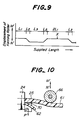
- the window molding member 50 has a pair of side portions 50a, 50b of the length L1, a pair of corner portions 50c, 50d of the length L2 and an upper portion 50e of the length L3, the relation between the displacement of the forming roller 66 in the directions M' and N' and the supplied length of the core element 57 is as shown in Fig. 9.
- the forming roller 66 assumes its uppermost position and is out of contact with the surface of the lip section 61, while the cutter member 65 extends slightly into the projection 62 of the lip section 61 so that a controlled small amount of material is removed from the projection 62, as shown in Fig. 8.
- the servomotor 69 is actuated in the normal direction, displacing the forming roller 66 in the direction N'.
- the forming roller 66 comes into contact with the lip section 61 to deflect this section counterclockwisely with reference to the leg section 58, from an initial angular position shown in Fig. 7 to a deflected angular position shown in Fig. 5.
- Such a deflection of the lip section 61 causes the projection 62 to be lowered, as seen in Figs. 5 to 7, whereas the cutter member 65 assumes a fixed position with reference to the extrusion die 24, so that the projection 62 is subjected to the removal of the material with a gradually increasing depth.
- the servomotor 69 is stopped so that the forming roller 66 is maintained in its lowermost position.
- the resultant maximum deflection of the lip section 61 corresponds to the removal of the material from the projection 62 with the maximum depth.
- the forming roller 66 is maintained in this position until the detector of the measuring station detects completion of the supply of the length L3 of the core element 57.
- the servomotor 69 is then actuated in the reverse direction to displace the forming roller 66 toward the uppermost position.
- the lip section 61 begins to restore into the initial angular position shown in Fig. 8, and the projection 62 thus moves upwardly with reference to the cutter member 65, so that the cutter member 65 removes material from the projection 62 with a gradually decreasing depth.
- the servomotor 69 is stopped as the detector of the measuring station detects completion of the length L2 of the core element 57, and the forming roller 66 is maintained in its uppermost position shown in Fig. 7, for a new cycle of operation, until twice the length L1 of the core element 57 is supplied to the extrusion die 24.
- the extruded body 25 is then cooled and solidified, and is further supplied to the second cutting station, like the station 30 shown in Fig. 2, where it is cut into the predetermined length of the window molding member 50 at a point X shown in Fig. 9, which is at the center of the two side portions.
- FIG. 10 A modification to the above-mentioned embodiment is shown in Fig. 10, in which the cutter member 70 is arranged on or adjacent to the extrusion die 24 and is movable in the directions P' and Q', synchronously with the movement of the forming roller 66 in the directions M' and N'.
- the depth with which material is removed from the projection 62 is varied by the movement of the cutter member 70, while the forming roller 66 serves to deform the lip section 61 while it is still hot and soft.
- the window molding member 50 shown in Figs. 3 and 4 can be produced in a continuous manner as described above.
- a strip-like retainer member 71 with a plurality of retaining fins is adhered to the side and upper webs 52a of the automobile body panel 52.
- the rubber dam 53 is preliminary secured onto the periphery of the rear surface of the window plate 51 which is then applied with adhesive material 53.
- the window plate 51 is then temporarily supported on the flange 52b of the body panel 52, and the leg section 58 of the molding member 50 is inserted, before the adhesive material 53 hardens, into the gap 59 between the body panel 52 and the window plate 51, engaging fins 58a and 58b of the leg section 58 with the retaining fins of the retainer member 71 and the rear edge of the window plate 51, respectively.
- the present invention provides a novel method of producing elongate molding members for automobiles, whereby the longitudinally variable cross-sectional shape of the molding member can be readily obtained essentially based on extrusion molding technology, simply by removing a controlled amount of the synthetic resin material from a predetermined location of the continuous body after it has been extruded, and by subsequently cutting the continuous body into a predetermined length of the molding member.
- the present invention is advantageous in that all the process steps can be carried out continuously, as contrasted with the conventional injection molding method, so that it is possible to produce the molding member with the desired, longitudinally variable cross-sectional shape, by means of a compact arrangement of the facility, and with a markedly improved productivity.
Description
- The present invention relates to a method of producing molding members, for instance for automobiles, formed at least partly of a synthetic resin material.
- An automobile employs various kinds of elongate molding members formed at least partly of a synthetic resin material, such as drip molding members, front and rear window molding members, etc. Of these, the drip molding member extends along the front pillar and the side edge of the roof panel of the vehicle body, while front and rear window molding members extend respectively along the periphery of the front and rear window plates, i.e. along the front and rear pillars and the front and rear edges of the roof panel. A variety of requirements are imposed on the molding members, mainly from design and/or functional viewpoint, and resulted in an increased demand in the automobile industry for the molding members whose cross-sectional shape varies in the longitudinal direction.
- More particularly, one proposal is directed to a window molding member having side portions with a first predetermined cross-sectional shape, an upper portion with a second predetermined cross-sectional shape, and corner portions arranged between the side and upper portions, where the cross-sectional shape changes gradually from the first to the second.
- Another proposal is directed to a drip molding member composed of a core element in the form of a metal strip which has been shaped into the desired cross-sectional shape, as well as upper and lower lip elements of synthetic resin material which are integral with the core element and molded such that the core element is partly exposed to, and visible from outside as a longitudinally extending ornamental portion with a metallic luster. The lower lip element is of a cross-sectional shape that is substantially constant throughout the entire length, while the upper lip element has a pillar portion with a relatively wide first cross-sectional shape, a roof portion with a relatively narrow second cross-sectional shape, and a corner portion between the pillar and roof portions, where the cross-sectional shape changes gradually from the first to the second.
- To produce elongate molding members whose cross-sectional shape varies in the longitudinal direction, it has been a conventional practice to use a process which includes preparation of the core element by shaping the raw metal strip into the desired cross-sectional shape with a roll forming machine, press machine, etc., placing each core element in the mold of an injection molding machine, and subsequently molding the synthetic resin material into the desired configuration. With such a process, however, since the entire core element of the elongate molding member has to be completely accommodated in the mold, the molding machine as a whole becomes very bulky and requires a substantial space in the factory. Moreover, the process involves relatively complex steps with which the molding members can be produced only one by one, and it is thus difficult to improve the productivity.
- Another possibility for the production of such molding members is to physically divide each molding member into first and second extruded portions with the respectively predetermined cross-sectional shapes, which are connected with each other either by an injection molding process or by using a separate connection piece. However, connection of the two portions by means of the injection molding accompanies formation of undesirable burrs along the junctions and resultant deterioration in the appearance, while use of the separate connection piece results in the increased number of the required components and assembly steps.
- GB-A-2126151 shows a process in which a molding member having a lip portion is cut in a predetermined pattern by engagement with a cutter movable laterally to the member.
- The preamble of claim 1 is based on this disclosure.
- EP 118397 shows a device for extruding a molding member with a lip portion. This lip is immediately following the extrusion step, selectively permanently deflected from its extruded shape.
- Therefore, it is a primary object of the present invention to provide a novel method of producing elongate molding members for automobiles, having a cross-sectional shape which is variable in the longitudinal direction, in a facilitated manner and with an improved productivity.
- According to the present invention, there is provided a method of producing a molding member for instance for a front or rear window for an automobile which includes, viewed in cross-section, a main body adapted to cover a gap formed between a window plate and an automobile body panel, a lip section projecting from said main body and adapted to cover the outer periphery of said window plate, the molding member being formed at least partly of a synthetic resin and the method including the steps of extruding the synthetic resin material into an elongate continuous body with a substantially constant cross-section throughout the length thereof; and removing from a predetermined location of said continuous body a controlled amount of the synthetic resin material, synchronously with the extrusion of the synthetic resin material, such that the cross-section of said continuous body varies in the longitudinal direction thereof, characterised in that said main body further comprises a ridge section projecting from the lip section for preventing flow of water across said ridge section, and in that said controlled amount of the synthetic resin material is removed from that portion of said continuous body which corresponds to said ridge section of said molding member, by deflecting the lip section of the main body along the part from which the controlled amount is to be removed such that the ridge section engages means by which the controlled amount is removed and in that the continuous body is subsequently cut into predetermined lengths.
- With the above-mentioned method of the present invention, the longitudinally variable cross-sectional shape of the molding member can be readily obtained essentially based on extrusion molding technology, simply by removing a controlled amount of the synthetic resin material from a predetermined location of the continuous body after it has been extruded, and by subsequently cutting the continuous body into a predetermined length of the molding member. According to the present invention, all the process steps can be carried out continuously, as contrasted with the conventional injection molding method, so that it is possible to produce the molding members with the desired, longitudinally variable cross-sectional shape, by means of a compact arrangement of the facility, and with a markedly improved productivity.
- Moreover, connection of separately extruded portions of a molding member, either by means of an injection molding process or by a connection piece, is not necessary, so that the present invention does not require the assembly of a plurality of components when producing a molding member, and preserves an excellent appearance of the product in an advantageous manner.
- Fig. 1 is a perspective view of an automobile with molding members which may be produced by the method in accordance with the present invention;
- Fig. 2 is a system diagram of the production line for carrying out the method of the present invention, which is adapted to produce various molding members;
- Fig. 3 is a sectional view of the side portion of the window molding member, which may be produced by the method in accordance with the present invention, and which has been secured to an automobile body;
- Fig. 4 is a sectional view of the upper portion of the window molding member shown in Fig. 3;
- Fig. 5 is a front view of the first cutting station adapted to produce the window molding member shown in Figs. 3 and 4;
- Fig. 6 is a sectional view taken substantially along the line B-B in Fig. 5;
- Fig. 7 is a front view similar to Fig. 5, but showing a different operational position of the forming roller;
- Fig. 8 is a schematic view showing the length of each portion of the window molding member;
- Fig. 9 is a diagram showing the relation between the displacement of the forming roller and the supplied length of the core element;
- Fig. 10 is a side view showing the modification to the cutting station shown in Figs. 5 and 6;
- There is shown in Fig. 1 an automobile designated as a whole by reference numeral 1, which is provided with various kinds of elongate molding members composed at least partly of a suitable synthetic resin material. These molding member include, among others, a front
window molding member 2, adrip molding member 3, etc., and the present invention is applicable to produce these elongate molding members with an improved productivity, as will be fully explained hereinafter. - The front
window molding member 2 is arranged along the periphery of side or the windshield plate, and includes a pair of side orpillar portions 2a extending along the front pillars of the automobile 1, respectively, an upper or roof portion 2b extending along the front edge of the roof panel of the automobile 1, and a pair of corner portions 2c arranged between thepillar portions 2a and that roof portion 2b. Eachpillar portion 2a has a predetermined first cross-sectional shape which is substantially constant throughout the entire length of thatportion 2a. Similarly, the roof portion 2b has a predetermined second cross-sectional shape which is substantially constant throughout the entire length of that portion 2b, but which is different from that of thepillar portion 2a. Consequently, the shape of thepillar portion 2a gradually changes to that of the roof portion 2b in each corner portion 2c, or in its neighbourhood. - On the other hand, the
drip molding member 3 is arranged along the front pillar and the side edge of the roof panel of the automobile. - The abovementioned molding members, 2,3 can be produced in the manner to be described hereinafter. Just for the sake of convenience, the following description will be made with reference to the production of the
drip molding member 3. - There is shown in Fig. 2 a system diagram of the production line for carrying out the method according to the present invention. The production line includes an uncoiler 11 from which a
metal strip 12 is continuously supplied by a pair ofpinch rollers 13. Another roller 14 serves to continuously supply aprotective tape 15 which is separably adhered, by means of a pair ofadhesion rollers 16, onto that portion of themetal strip 12 which eventually forms ornamental portions 5 of themolding member 3 with the desired metallic luster, and which has thus to be protected by thetape 15. Themetal strip 12 applied with theprotective tape 15 forms acomposite body 17 which, subsequently, is subjected to surface degreasing and cleaning at acleaning station 18 for carrying out a sanding or the like treatment, is coated with an adhesive material at aroll coating station 19, and is subjected to baking at thebaking station 20. Thecomposite body 17 is further passed through and cooled in acooling tank 21, and is then shaped into a desired, longitudinally constant cross-section at aroll forming machine 22 to form acontinuous core element 4 of themolding member 3. - The
core element 4 so obtained is supplied to ameasuring station 23 which includes a rotary encoder or the like detector for measuring the supplied length of thecore element 4, and then to anextrusion die 24 which is further supplied with a suitable synthetic resin material in its heated molten state. The molten synthetic resin material is co-extruded from the extrusion die 24 as a continuousextruded body 25 in which the upper andlower lip elements 6, 7 are made integral with thecore element 4, whereby theextruded body 25 has a substantially constant cross-section which corresponds to that of the pillar portion 3a of themolding member 3. - To produce molding members with a longitudinally variable cross-section, in accordance with the illustrated preferred embodiment of the present invention, the
extruded body 25 as extruded from theextrusion die 24 is further subjected to the removal of a controlled amount of synthetic resin material from the predetermined location of theupper lip element 6. To this end, there is provided acontroller 26 which is adapted to receive from the measuring station 23 a signal representing the supplied length of thecore element 4, while afirst cutting station 27 is arranged on the exit or discharge side of thedie 24 and is adapted to be controlled by thecontroller 26 according to the supplied length of thecore element 4. Theextruded body 25 is subsequently passed through acooling tank 28 where it is cooled, and is then advanced by a take-updevice 29 and cut into the predetermined length of the product at asecond cutting station 30 which, too, is controlled by thecontroller 26 according to the supplied length of thecore element 4. - Preferably, the removal of the synthetic resin material is carried out while the
extruded body 25 is still hot and soft. - The
extruded body 25 subjected to the removal of the synthetic resin material at thefirst cutting station 27 is then supplied to thesecond cutting station 30 where it is cut into the predetermined length of the desiredmolding member 3 at predetermined positions of theextruded body 25 which correspond to the centers of the length 2L₁ and 2L₃, respectively. - Furthermore, by repeating the above-mentioned operations, the molding members can be continuously produced one by one, in an efficient and reliable manner.
- An embodiment of the present invention, which is applied to the production of the window molding member, will now be explained with reference to Figs. 3 and 4. The molding member to be produced is designated as a whole by
reference numeral 50, and is adapted to be arranged along the outer periphery of a front orrear window plate 51 which is formed of a transparent inorganic glass or transparent synthetic resin, such as polycarbonate resin, acrylic resin, or the like. Thewindow plate 51 is secured to theautomobile body panel 52 by means of anadhesive material 53, with arubber dam member 54 arranged between theplate 51 and thebody panel 52. Thewindow plate 51 is further provided, on its rear surface, with an opaque printedlayer 55 which extends along the periphery of theplate 51 so that theadhesive material 53 and thedam member 54 are not visible from outside, and which thus provides a highly refined appearance. - The
window molding member 50 includes amain body 56 which is formed of flexible and/or soft polyvinylchloride (PVC) resin, ionomer resin, ethylene-vinyl acetate copolymer (EVA) resin, transparent cellulose acetate butylate (CAB) resin, appropriate synthetic rubber material or other suitable thermoplastic and elastomeric synthetic resin material with a flexibility. The material forming themain body 56 is extruded about a metal strip forming acore element 57 which is thus embedded in the synthetic resin material of themain body 56. - More particularly, as shown in Fig. 3 illustrating the cross-section of the
molding member 50 at its side portion when thewindow plate 51 is a front window plate, themain body 56 of thewindow molding member 50 includes aleg section 58 extending into agap 59 left between thewindow plate 51 and theautomobile body panel 52. Themain body 56 further includes a pair oflip sections leg section 58. Thelip section 60 has a free end which bears against the outer surface of theautomobile body panel 52, while thelip section 61 is formed with aprojection 62 in the form of a ridge near the free end thereof, which bears against the outer surface of thewindow plate 51. Theprojection 62 cooperates with the free end of thelip section 61 and thewindow plate 51 to define achannel 63 which serves to prevent side flow of the water orrain drops 64 across the front pillar of the automobile, from the front window plate toward the side window, and effectively preserves the driver's and/or navigator's sight through the side window, during the driving of the automobile in rainy climate condition. In other words, thechannel 63 guides the flow of water or rain drops 64 along the side edge of thefront window plate 51. - The
channel 63 thus extends along the front pillar of the automobile, but is not required along the junction between the upper edge of the front window plate and the roof panel of the automobile; rather, provision of such a channel along the upper edge of the front window plate is undesirable since the channel prevents realization of the so-called flush outer surface of the automobile. Hence, as particularly shown in Fig. 4 illustrating the cross-section of the upper portion of themolding member 50, thelip section 61 of themain body 56 in its upper portion is not provided with theprojection 62 with a sufficient length to define thechannel 63. Furthermore, thelip section 61 assumes an angular position with reference to theleg section 58, which is different from that shown in Fig. 3, and is in direct contact with the surface of thewindow plate 51 as shown in Fig. 4. This means that thewindow molding member 50 shown in Figs. 3 and 4 has a cross-section which varies in the longitudinal direction. - The
window molding member 50 shown in Figs. 3 and 4 can be produced by the method according to the present invention, with a production line which is substantially the same as that shown in Fig. 2. - According to the present embodiment, as shown in Figs. 5 to 7, the first cutting
station 27 includes astationary cutter member 65 which assumes a fixed position with reference to the extrusion die 24, a formingroller 66 supported by amovable frame 67 and adapted to be brought into contact with thelip section 61 of the extrudedbody 25 forming themolding member 50, thereby to deform thelip section 61 while it is still hot and soft. A screw threadedrod 68 connects theframe 67 with areversible servomotor 69 which, in turn, is connected to a controller, like thecontroller 26 as shown in Fig. 2. Thus, theservomotor 69 is adapted to displace the formingroller 66 in the direction M' or N' as shown by double arrow in Figs. 5 and 6, in accordance with the length of thecore element 57 supplied to the extrusion die 24. - Assuming that, as shown in Fig. 8, the
window molding member 50 has a pair ofside portions 50a, 50b of the length L₁, a pair ofcorner portions upper portion 50e of the length L₃, the relation between the displacement of the formingroller 66 in the directions M' and N' and the supplied length of thecore element 57 is as shown in Fig. 9. - More particularly, during the period in which the
die 24 discharges that portion of the extrudedbody 25 which corresponds to theside portions 50a, 50b of themolding member 50 with the length L₁, the formingroller 66 assumes its uppermost position and is out of contact with the surface of thelip section 61, while thecutter member 65 extends slightly into theprojection 62 of thelip section 61 so that a controlled small amount of material is removed from theprojection 62, as shown in Fig. 8. - As the detector of the measuring station detects the completion of the supply of the length L₁ of the
core element 57, or the beginning point of thecorner portion 50c of the length L₂, theservomotor 69 is actuated in the normal direction, displacing the formingroller 66 in the direction N'. During this movement, the formingroller 66 comes into contact with thelip section 61 to deflect this section counterclockwisely with reference to theleg section 58, from an initial angular position shown in Fig. 7 to a deflected angular position shown in Fig. 5. Such a deflection of thelip section 61 causes theprojection 62 to be lowered, as seen in Figs. 5 to 7, whereas thecutter member 65 assumes a fixed position with reference to the extrusion die 24, so that theprojection 62 is subjected to the removal of the material with a gradually increasing depth. - When the detector at the measuring station detects the completion of the supply of the length L₂ of the
core element 57, or the beginning of theupper portion 50e of themolding member 50 with the length L₃, theservomotor 69 is stopped so that the formingroller 66 is maintained in its lowermost position. The resultant maximum deflection of thelip section 61 corresponds to the removal of the material from theprojection 62 with the maximum depth. - The forming
roller 66 is maintained in this position until the detector of the measuring station detects completion of the supply of the length L₃ of thecore element 57. Theservomotor 69 is then actuated in the reverse direction to displace the formingroller 66 toward the uppermost position. Thelip section 61 begins to restore into the initial angular position shown in Fig. 8, and theprojection 62 thus moves upwardly with reference to thecutter member 65, so that thecutter member 65 removes material from theprojection 62 with a gradually decreasing depth. - The
servomotor 69 is stopped as the detector of the measuring station detects completion of the length L₂ of thecore element 57, and the formingroller 66 is maintained in its uppermost position shown in Fig. 7, for a new cycle of operation, until twice the length L₁ of thecore element 57 is supplied to the extrusion die 24. - The extruded
body 25 is then cooled and solidified, and is further supplied to the second cutting station, like thestation 30 shown in Fig. 2, where it is cut into the predetermined length of thewindow molding member 50 at a point X shown in Fig. 9, which is at the center of the two side portions. - A modification to the above-mentioned embodiment is shown in Fig. 10, in which the
cutter member 70 is arranged on or adjacent to the extrusion die 24 and is movable in the directions P' and Q', synchronously with the movement of the formingroller 66 in the directions M' and N'. The depth with which material is removed from theprojection 62 is varied by the movement of thecutter member 70, while the formingroller 66 serves to deform thelip section 61 while it is still hot and soft. - The
window molding member 50 shown in Figs. 3 and 4 can be produced in a continuous manner as described above. To arrange the molding member in place, first of all, a strip-like retainer member 71 with a plurality of retaining fins is adhered to the side andupper webs 52a of theautomobile body panel 52. Therubber dam 53 is preliminary secured onto the periphery of the rear surface of thewindow plate 51 which is then applied withadhesive material 53. Thewindow plate 51 is then temporarily supported on theflange 52b of thebody panel 52, and theleg section 58 of themolding member 50 is inserted, before theadhesive material 53 hardens, into thegap 59 between thebody panel 52 and thewindow plate 51, engagingfins leg section 58 with the retaining fins of theretainer member 71 and the rear edge of thewindow plate 51, respectively. - From the foregoing description, it will be appreciated that the present invention provides a novel method of producing elongate molding members for automobiles, whereby the longitudinally variable cross-sectional shape of the molding member can be readily obtained essentially based on extrusion molding technology, simply by removing a controlled amount of the synthetic resin material from a predetermined location of the continuous body after it has been extruded, and by subsequently cutting the continuous body into a predetermined length of the molding member. The present invention is advantageous in that all the process steps can be carried out continuously, as contrasted with the conventional injection molding method, so that it is possible to produce the molding member with the desired, longitudinally variable cross-sectional shape, by means of a compact arrangement of the facility, and with a markedly improved productivity.
Claims (5)
- A method of producing a molding member (2,3,50) for instance for a front or rear window for an automobile (1), which includes, viewed in cross-section, a main body (50) adapted to cover a gap formed between a window plate (51) and an automobile body panel (52), a lip section (61) projecting from said main body (50) and adapted to cover the outer periphery of said window plate (51), the molding member being formed at least partly of a synthetic resin and the method including the steps of extruding the synthetic resin material into an elongate continuous body (25) with a substantially constant cross-section throughout the length thereof; and removing from a predetermined location of said continuous body (25) a controlled amount of the synthetic resin material, synchronously with the extrusion of the synthetic resin material, such that the cross-section of said continuous body (25) varies in the longitudinal direction thereof, characterised in that said main body (50) further comprises a ridge section (62) projecting from the lip section (61) for preventing flow of water across said ridge section (62), and in that said controlled amount of the synthetic resin material is removed from that portion of said continuous body (25) which corresponds to said ridge section (62) of said molding member, by deflecting the lip section (61) of the main body (50) along the part from which the controlled amount is to be removed such that the ridge section (62) engages means (65) by which the controlled amount is removed and in that the continuous body (25) is subsequently cut into predetermined lengths.
- A method as claimed in claim 1, wherein said controlled amount of the synthetic resin material is removed from the continuous body (25) after the continuous body (25) has been extruded, while it is still hot and soft.
- The method as claimed in claim 1 or 2, wherein said continuous body (25) is formed by continuously supplying a core element (4,58) to an extrusion die (24) through which said synthetic resin material is extruded with said core element (4,58), and wherein said controlled amount of the synthetic resin material is removed from the continuous body (25) in accordance with the supplied length of said core element.
- The method as claimed in claim 1, 2 or 3, wherein said molding member is a front window molding member (2) for an automobile (1), and has an upper portion (2b) adapted to extend along the junction between an upper edge of said window plate and a roof panel of the automobile (1), and wherein said controlled amount of the synthetic resin material is removed from that portion of said continuous body (25) which forms said upper portion (2b) of said molding member.
- The method as claimed in claim 1, 2 or 3, wherein said molding member is a rear window molding member for an automobile, and has side portions to extend along the junction between side edges of said window plate and rear pillars of the automobile, and wherein said controlled amount of the synthetic resin material is removed from those portions of said continuous body which form the side portions of said molding member.
Priority Applications (2)
| Application Number | Priority Date | Filing Date | Title |
|---|---|---|---|
| EP92119916A EP0540061B1 (en) | 1988-01-29 | 1988-04-15 | Molding member and method of producing it |
| EP92119915A EP0541130B1 (en) | 1988-01-29 | 1988-04-15 | Molding members and method of producing them |
Applications Claiming Priority (2)
| Application Number | Priority Date | Filing Date | Title |
|---|---|---|---|
| JP63019289A JPH01195032A (en) | 1988-01-29 | 1988-01-29 | Preparation of window molding |
| JP19289/88 | 1988-01-29 |
Related Child Applications (2)
| Application Number | Title | Priority Date | Filing Date |
|---|---|---|---|
| EP92119916.2 Division-Into | 1992-11-23 | ||
| EP92119915.4 Division-Into | 1992-11-23 |
Publications (2)
| Publication Number | Publication Date |
|---|---|
| EP0325828A1 EP0325828A1 (en) | 1989-08-02 |
| EP0325828B1 true EP0325828B1 (en) | 1993-06-16 |
Family
ID=11995280
Family Applications (3)
| Application Number | Title | Priority Date | Filing Date |
|---|---|---|---|
| EP92119915A Expired - Lifetime EP0541130B1 (en) | 1988-01-29 | 1988-04-15 | Molding members and method of producing them |
| EP92119916A Expired - Lifetime EP0540061B1 (en) | 1988-01-29 | 1988-04-15 | Molding member and method of producing it |
| EP88303433A Expired - Lifetime EP0325828B1 (en) | 1988-01-29 | 1988-04-15 | Method of producing molding members |
Family Applications Before (2)
| Application Number | Title | Priority Date | Filing Date |
|---|---|---|---|
| EP92119915A Expired - Lifetime EP0541130B1 (en) | 1988-01-29 | 1988-04-15 | Molding members and method of producing them |
| EP92119916A Expired - Lifetime EP0540061B1 (en) | 1988-01-29 | 1988-04-15 | Molding member and method of producing it |
Country Status (7)
| Country | Link |
|---|---|
| US (2) | US4865796A (en) |
| EP (3) | EP0541130B1 (en) |
| JP (1) | JPH01195032A (en) |
| KR (1) | KR940000620B1 (en) |
| AU (1) | AU593991B2 (en) |
| CA (1) | CA1323163C (en) |
| DE (3) | DE3881860T2 (en) |
Families Citing this family (71)
| Publication number | Priority date | Publication date | Assignee | Title |
|---|---|---|---|---|
| JPS63141849A (en) * | 1986-12-01 | 1988-06-14 | Hashimoto Forming Co Ltd | Molding and its manufacture |
| JPH0628910B2 (en) * | 1987-09-29 | 1994-04-20 | 橋本フォーミング工業株式会社 | Window molding manufacturing method |
| JPH0615292B2 (en) * | 1987-11-30 | 1994-03-02 | 橋本フォーミング工業株式会社 | Window molding and manufacturing method thereof |
| JPH0640491Y2 (en) * | 1988-03-28 | 1994-10-26 | 株式会社ニフコ | Peripheral mall for automobile window glass |
| DE3819916C2 (en) * | 1988-06-11 | 1996-12-19 | Erfurt Umformtechnik Gmbh | Process for dosing the amount of material in the production of moldings from curable molding materials |
| CA2002768C (en) * | 1988-11-10 | 1997-10-07 | Tatsuya Tamura | Method of manufacturing automobile windows |
| JPH0278408U (en) * | 1988-12-06 | 1990-06-15 | ||
| US5009947A (en) * | 1989-04-28 | 1991-04-23 | Schlegel Corporation | Elastomeric strip and method of manufacture |
| AU620286B2 (en) * | 1989-08-07 | 1992-02-13 | Hashimoto Forming Industry Co. Limited | Method of, and apparatus for manufacturing elongate articles |
| JP2823601B2 (en) * | 1989-09-25 | 1998-11-11 | 株式会社イノアックコーポレーション | Window mall |
| US5203946A (en) * | 1989-09-25 | 1993-04-20 | Hashimoto Forming Industry Co., Ltd. | Method of, and apparatus for manufacturing elongate plastic articles |
| US5061335A (en) * | 1989-09-25 | 1991-10-29 | Hashimoto Forming Industry Co., Ltd. | Method of, and apparatus for manufacturing elongate plastic articles |
| US5233805A (en) * | 1989-10-14 | 1993-08-10 | Tokai Kogyo Kabushiki Kaisha | Molding for automotive front glass and molding apparatus |
| JPH03143730A (en) * | 1989-10-27 | 1991-06-19 | Tokai Kogyo Kk | Automobile front windshield molding and molding device thereof |
| JP3081211B2 (en) * | 1989-10-27 | 2000-08-28 | 東海興業株式会社 | Automotive windshield molding and method of manufacturing the same |
| JPH0745379Y2 (en) * | 1989-11-22 | 1995-10-18 | 東海興業株式会社 | Automotive windshield sealing equipment |
| DE4025166C2 (en) * | 1990-08-08 | 1999-01-14 | Siv Deutschland Gmbh | Process for producing a continuous polyurethane bead |
| US5174623A (en) * | 1990-09-06 | 1992-12-29 | Tokai Kogyo Kabushiki Kaisha | Automobile windshield molding |
| US5190338A (en) * | 1990-09-06 | 1993-03-02 | Tokai Kogyo Kabushiki Kaisha | Automobile windshield molding and method of producing the same |
| USRE37737E1 (en) | 1990-09-06 | 2002-06-11 | Tokai Kogyo Kabushiki Kaisha | Automobile windshield molding and method of producing the same |
| US5656223A (en) * | 1991-07-25 | 1997-08-12 | Tokai Kogyo Kabushiki Kaisha | Windshield molding for vehicles and the production method thereof |
| DE482901T1 (en) * | 1990-10-23 | 1992-09-24 | Tokai Kogyo K.K., Obu, Aichi, Jp | MOLDED PART FOR MOTOR VEHICLE WINDSHIELD AND DEVICE FOR THE PRODUCTION THEREOF. |
| US6196615B1 (en) | 1990-10-23 | 2001-03-06 | Tokai Kogyo Kabushiki Kaisha | Automobile windshield molding and the method of producing the same |
| US6095586A (en) * | 1990-10-23 | 2000-08-01 | Tokai Kogyo Kabushiki Kaisha | Automobile windshield molding and the method of producing the same |
| US5281291A (en) * | 1990-10-24 | 1994-01-25 | Tokai Kogyo Kabushiki Kaisha | Molding and method of producing the same |
| US5229054A (en) * | 1990-11-30 | 1993-07-20 | Tokai Kogyo Kabushiki Kaisha | Method of manufacturing automobile windshield molding |
| US5492387A (en) * | 1991-03-15 | 1996-02-20 | Tokai Kogyo Kabushiki Kaisha | Automobile windshield molding |
| US5257450A (en) * | 1991-03-29 | 1993-11-02 | Hashimoto Forming Industry Co., Ltd. | Automobile windshield molding member and method of manufacturing the same |
| JP2600511B2 (en) * | 1991-03-29 | 1997-04-16 | 橋本フォーミング工業株式会社 | Window molding and manufacturing method thereof |
| JP3150361B2 (en) * | 1991-05-31 | 2001-03-26 | 東海興業株式会社 | Vehicle molding and method of manufacturing the same |
| US5507992A (en) * | 1991-07-25 | 1996-04-16 | Tokai Kogyo Kabushiki Kaisha | Windshield molding for vehicles and the production method thereof |
| FR2683190B1 (en) * | 1991-09-30 | 1995-08-25 | Tokai Kogyo Co Ltd | PROFILE FOR WINDSHIELD AND MANUFACTURING METHOD THEREOF. |
| US5266021A (en) * | 1991-10-10 | 1993-11-30 | Jacobson Theodore L | Apparatus for continuous forming of complex molded shapes |
| US5149478A (en) * | 1991-11-18 | 1992-09-22 | The Standard Products Company | Forming decorative trim strips from continuous extrusions |
| US5395563A (en) * | 1992-02-05 | 1995-03-07 | Toyoda Gosei Co., Ltd. | Manufacturing method and apparatus for forming an elongate body having thickness change |
| JP3072941B2 (en) * | 1992-06-26 | 2000-08-07 | 東海興業株式会社 | Manufacturing method of automotive molding |
| JP2598973Y2 (en) * | 1992-08-18 | 1999-08-23 | 東海興業株式会社 | Automotive wind molding |
| JPH06144003A (en) * | 1992-11-04 | 1994-05-24 | Nifco Inc | Molding for front glass |
| GB9304411D0 (en) * | 1993-03-04 | 1993-04-21 | Silent Channel Prod Ltd | Vehicle window frame |
| ES2107058T3 (en) * | 1993-03-11 | 1997-11-16 | Henniges Elastomer Kunststoff | BODY WINDOW. |
| DE4313194C1 (en) * | 1993-04-22 | 1994-04-07 | Metzeler Automotive Profiles | Mfg. elastomeric strip with variable section lip - using two movable, opposing needles on die ring to cut into extrudate lip before vulcanisation |
| US5447670A (en) * | 1993-04-28 | 1995-09-05 | Toyoda Gosei Co., Ltd. | Method of and apparatus for forming weather strip by extrusion |
| US5360251A (en) * | 1993-11-09 | 1994-11-01 | Nifco, Inc. | Flush mount molding member |
| US6007319A (en) * | 1993-11-30 | 1999-12-28 | Continuous Molding, Inc. | Continuous forming of complex molded shapes |
| US5529650A (en) * | 1994-05-24 | 1996-06-25 | Green Tokai Co., Inc. | Method of making flocked, vehicle molding |
| JP3019729B2 (en) * | 1994-09-22 | 2000-03-13 | 豊田合成株式会社 | Method and apparatus for extruding a weatherstrip |
| GB9424188D0 (en) * | 1994-11-30 | 1995-01-18 | Heywood Williams Plastics Ltd | Window security |
| JPH0911739A (en) * | 1995-06-29 | 1997-01-14 | Toyoda Gosei Co Ltd | Vehicular window molding |
| KR0145834B1 (en) * | 1995-10-06 | 1998-08-17 | 전성원 | Roof molding for roof rain gutter |
| CA2216783C (en) * | 1996-01-30 | 2004-11-23 | Hashimoto Forming Industry Co., Ltd. | Elongate composite member having a longitudinally varying cross-sectional shape, as well as method of, and apparatus for manufacturing the same |
| JP3206439B2 (en) * | 1996-06-28 | 2001-09-10 | 東海興業株式会社 | Molding manufacturing method and apparatus |
| US5874034A (en) * | 1997-04-14 | 1999-02-23 | Xerox Corporation | Swell reducing extrusion die |
| US5964979A (en) * | 1997-08-15 | 1999-10-12 | 3M Innovative Properties Company | Sealing method and article |
| GB2334990A (en) * | 1998-03-03 | 1999-09-08 | Draftex Ind Ltd | A sealing strip for a sunroof comprising a water-directing lip along part of its length |
| US6224145B1 (en) * | 1998-10-30 | 2001-05-01 | Inoac Corporation | Roof molding for an automobile and method of trimming the same |
| US6513854B2 (en) * | 2001-02-15 | 2003-02-04 | Centre Luxembourgeois De Recherches Pour Le Verre Et La Ceramique S.A. (C.R.V.C.) | Method of applying extruded profile to corners of a window glazing |
| US6854784B2 (en) * | 2002-05-22 | 2005-02-15 | Honda Giken Kogyo Kabushiki Kaisha | Automobile drip molding, mounting construction thereof and method of mounting |
| JP3866157B2 (en) * | 2002-05-22 | 2007-01-10 | 本田技研工業株式会社 | Automotive drip molding |
| FR2854360B1 (en) * | 2003-04-29 | 2006-06-02 | Silvatrim Sa | METHOD FOR MANUFACTURING A TRIM HAVING AN EXTRUDED BODY AND A TRAPPER OF THE SAME ASPECT |
| CA2527223C (en) * | 2003-06-04 | 2012-12-04 | Decoma International Inc. | Rigid plastic glass run channel |
| FR2864919B1 (en) * | 2004-01-14 | 2006-03-24 | Hutchinson | DYNAMIC CONTINUOUS APPLICATION CELL OF AN ADHESIVE SEAL ON A RECEPTION SUPPORT. |
| DE102004050861B4 (en) * | 2004-10-18 | 2009-10-08 | Webasto Ag | Mold and method for producing a plastic encapsulated, overmolded or foam-coated plate |
| US8096601B2 (en) * | 2005-06-22 | 2012-01-17 | Magna Car Top Systems Gmbh | Rear window in a rear roof section of an openable roof vehicle |
| US8109812B2 (en) * | 2007-12-14 | 2012-02-07 | Toyota Motor Engineering & Manufacturing North America, Inc. | Motor vehicle instrument panel assembly having a conduit with a gasket support lip |
| US9174519B2 (en) | 2011-10-18 | 2015-11-03 | Henniges Automotive Sealing Systems North America Inc. | Weatherstrip assembly having a variable length shim |
| US9127457B2 (en) * | 2012-07-10 | 2015-09-08 | King Saud University | Machine for deforming and cutting plastic strips for enhancing concrete |
| WO2015006060A2 (en) * | 2013-07-08 | 2015-01-15 | 3M Innovative Properties Company | Installation tools, systems, and methods for flexible profile moldings, such as window film adhesive attachment articles |
| FR3018251B1 (en) * | 2014-03-07 | 2017-09-15 | Renault Sas | DEFLECTOR FOR A MOTOR VEHICLE, IN PARTICULAR FOR A WINDSHIELD |
| JP6268081B2 (en) * | 2014-12-05 | 2018-01-24 | 片山工業株式会社 | Molding |
| ES2843749T3 (en) * | 2016-11-17 | 2021-07-20 | Milan Conception Inc | Cutting unit for cutting rough profiles |
| CN106944942B (en) * | 2017-04-28 | 2019-04-05 | 赵永兴 | A kind of clamp-on pipe vise |
Family Cites Families (42)
| Publication number | Priority date | Publication date | Assignee | Title |
|---|---|---|---|---|
| DE1235164B (en) * | 1967-02-23 | Porsche Kg | Profile strip for framing or holding windows, in particular windshields of motor vehicles | |
| US2126151A (en) * | 1936-08-31 | 1938-08-09 | Monsanto Chemicals | Process of flocculation |
| US2610714A (en) * | 1951-11-28 | 1952-09-16 | Detroit Macoid Corp | Sealing strip |
| US2763346A (en) * | 1953-06-09 | 1956-09-18 | Gen Motors Corp | Connector strip |
| CH363794A (en) * | 1957-08-09 | 1962-08-15 | Basf Ag | Process and device for the production of extruded profile rods from thermoplastics |
| DE1630375C3 (en) * | 1967-10-20 | 1979-11-29 | Daimler-Benz Ag, 7000 Stuttgart | Edging strip for laterally curved windshields of motor vehicles |
| NL160422C (en) * | 1974-05-21 | 1979-10-15 | Philips Nv | PROCESS FOR MANUFACTURE OF A COAXIAL CABLE AND COAXIAL CABLE OBTAINED BY THIS PROCESS. |
| JPS50158659A (en) * | 1974-06-14 | 1975-12-22 | ||
| DE2617123A1 (en) * | 1976-04-17 | 1977-10-27 | Huebner Gummi & Kunststoff | Extruding elastomer with varying section - by mounting adjustable supplementary tool in outlet orifice and moving as required |
| JPS5411977A (en) * | 1977-06-30 | 1979-01-29 | Inoue Gomu Kogyo Kk | Manufacture of synthetic resin lace |
| US4256685A (en) * | 1977-07-05 | 1981-03-17 | W. James Kemerer | Variable profile extrusion method |
| JPS5756214A (en) * | 1980-09-19 | 1982-04-03 | Hashimoto Forming Co Ltd | Method and device for terminal cutting of synthetic resin molding |
| JPS57109913U (en) * | 1980-12-26 | 1982-07-07 | ||
| DE3107218A1 (en) * | 1981-02-26 | 1982-09-02 | Dr.Ing.H.C. F. Porsche Ag, 7000 Stuttgart | RAIN GUTTER FOR A VEHICLE, IN PARTICULAR MOTOR VEHICLE |
| DE3148212A1 (en) * | 1981-12-05 | 1983-06-09 | Continental Gummi-Werke Ag, 3000 Hannover | EXTRUSION PRESS |
| DE3224906C2 (en) * | 1982-07-03 | 1985-09-12 | Continental Gummi-Werke Ag, 3000 Hannover | Device for producing profile strands from elastomeric materials |
| JPS5970528A (en) * | 1982-10-14 | 1984-04-21 | Nishikawa Gomme Kogyo Kk | Extrusion forming method and apparatus |
| JPS5978837A (en) * | 1982-10-28 | 1984-05-07 | Kinugawa Rubber Ind Co Ltd | Molding method of weather strip for automobile |
| JPS5983519U (en) * | 1982-11-30 | 1984-06-06 | 西川ゴム工業株式会社 | Extrusion molding equipment |
| IT1157134B (en) * | 1982-12-10 | 1987-02-11 | Saiag Spa | PROCEDURE AND EQUIPMENT FOR REALIZING A DRAWN CONTINUOUS EXTRUSION IN PARTICULAR A SEAL GASKET FOR BODYWORKS OF MOTOR VEHICLES PRESENTING SUBSEQUENT LENGTHS OF PRE-DETERMINED LENGTHS WITH EACH PRACTICAL PERFORMANCE AND PRACTICAL PERFORMANCE |
| IT1161480B (en) * | 1983-02-03 | 1987-03-18 | Saiag Spa | DEVICE TO MODIFY DURING THE EXTRUSION THE INCLINATION OR ORIENTATION OF A LONGITUDINAL FLAP OF AN EXTRUDED SEAL FOR MOTOR VEHICLES AND GASKET OBTAINED WITH SUCH DEVICE |
| IT1165544B (en) * | 1983-02-17 | 1987-04-22 | Saiag Spa | EQUIPMENT FOR SYNCHRONIZING THE SECTION VARIATIONS OF A DRAWING PARTICULARLY OF A SEAL FOR MOTOR VEHICLE BODIES WITH THE ADVANCE OF THE DRAWN IN AN EXTRUSION MACHINE AND EXTRUSION MACHINE AND EXTRUSION MACHINE INCLUDING THE EXTRUSION MACHINE INCLUDING THE EXTRUSION MACHINE |
| JPS60104322A (en) * | 1983-11-11 | 1985-06-08 | Shiraki Kinzoku Kogyo Kk | Belt molding and manufacture thereof |
| DE3427346A1 (en) * | 1984-07-25 | 1986-01-30 | Continental Gummi-Werke Ag, 3000 Hannover | METHOD FOR PRODUCING SEALING AND / OR CLAMP PROFILING STRIPS |
| JPS61135824A (en) * | 1984-12-05 | 1986-06-23 | Kinugawa Rubber Ind Co Ltd | Automobile window weather strip |
| JPS61167521A (en) * | 1985-01-21 | 1986-07-29 | Toyoda Gosei Co Ltd | Manufacture of weather strip |
| JPS61202917A (en) * | 1985-03-05 | 1986-09-08 | Kinugawa Rubber Ind Co Ltd | Flush mount molding for car |
| IT1183795B (en) * | 1985-04-03 | 1987-10-22 | Saiag Spa | PROCEDURE AND DEVICE FOR THE MANUFACTURE OF A GASKET FOR VEHICLES AND GASKET OBTAINED WITH THE PROCEDURE |
| JPS62178422A (en) * | 1986-01-31 | 1987-08-05 | Hashimoto Forming Co Ltd | Window molding |
| DE3608223A1 (en) * | 1986-03-12 | 1987-10-15 | Huehoco Bandeisen Und Metallwa | METAL CARRIER TAPE FOR PROFILE BARS WITH SHEATH AND ORNAMENTAL OR FUNCTIONAL STRIPES |
| JPH0626922B2 (en) * | 1986-03-15 | 1994-04-13 | 株式会社ニフコ | Peripheral mold for automobile window glass |
| JPH069929B2 (en) * | 1986-03-31 | 1994-02-09 | 橋本フォーミング工業株式会社 | Window molding |
| JPH0517290Y2 (en) * | 1986-05-30 | 1993-05-10 | ||
| JPH0645299B2 (en) * | 1986-05-30 | 1994-06-15 | 橋本フオ−ミング工業株式会社 | Window molding and manufacturing method thereof |
| JP2821739B2 (en) * | 1986-06-30 | 1998-11-05 | 橋本フォーミング工業 株式会社 | Window molding |
| JPH0729547B2 (en) * | 1986-06-30 | 1995-04-05 | 橋本フオ−ミング工業株式会社 | Vehicle window |
| JPH0698895B2 (en) * | 1986-06-30 | 1994-12-07 | 橋本フオ−ミング工業株式会社 | Manufacturing method for window molding |
| US4757660A (en) * | 1986-12-04 | 1988-07-19 | Tokiwa Chemical Industries Co., Ltd. | Front glass mouldings |
| US4757659A (en) * | 1986-12-04 | 1988-07-19 | Tokiwa Chemical Industries Co., Ltd. | Front glass mouldings |
| US4833847A (en) * | 1987-03-12 | 1989-05-30 | Toyoda Gosei Co., Ltd. | Flush mounting molding |
| JPH0636977Y2 (en) * | 1988-01-30 | 1994-09-28 | 株式会社ニフコ | Adhesive wind molding installation device |
| JPH06338023A (en) * | 1993-05-28 | 1994-12-06 | Sony Corp | Magnetic head |
-
1988
- 1988-01-29 JP JP63019289A patent/JPH01195032A/en active Granted
- 1988-04-13 US US07/180,893 patent/US4865796A/en not_active Expired - Lifetime
- 1988-04-15 DE DE88303433T patent/DE3881860T2/en not_active Expired - Fee Related
- 1988-04-15 EP EP92119915A patent/EP0541130B1/en not_active Expired - Lifetime
- 1988-04-15 DE DE3855847T patent/DE3855847T2/en not_active Expired - Fee Related
- 1988-04-15 AU AU14692/88A patent/AU593991B2/en not_active Ceased
- 1988-04-15 DE DE3854946T patent/DE3854946T2/en not_active Expired - Fee Related
- 1988-04-15 EP EP92119916A patent/EP0540061B1/en not_active Expired - Lifetime
- 1988-04-15 EP EP88303433A patent/EP0325828B1/en not_active Expired - Lifetime
- 1988-04-18 KR KR1019880004408A patent/KR940000620B1/en not_active IP Right Cessation
- 1988-04-19 CA CA564516A patent/CA1323163C/en not_active Expired - Fee Related
-
1989
- 1989-07-13 US US07/379,283 patent/US5074610A/en not_active Expired - Lifetime
Also Published As
| Publication number | Publication date |
|---|---|
| KR940000620B1 (en) | 1994-01-26 |
| JPH0564584B2 (en) | 1993-09-14 |
| JPH01195032A (en) | 1989-08-04 |
| DE3855847T2 (en) | 1997-11-27 |
| US5074610A (en) | 1991-12-24 |
| EP0325828A1 (en) | 1989-08-02 |
| DE3854946T2 (en) | 1996-05-30 |
| DE3881860T2 (en) | 1993-09-30 |
| DE3854946D1 (en) | 1996-03-07 |
| DE3881860D1 (en) | 1993-07-22 |
| AU1469288A (en) | 1989-08-03 |
| EP0541130B1 (en) | 1997-03-26 |
| CA1323163C (en) | 1993-10-19 |
| AU593991B2 (en) | 1990-02-22 |
| EP0540061B1 (en) | 1996-01-24 |
| DE3855847D1 (en) | 1997-04-30 |
| US4865796A (en) | 1989-09-12 |
| EP0540061A1 (en) | 1993-05-05 |
| EP0541130A1 (en) | 1993-05-12 |
| KR890011692A (en) | 1989-08-22 |
Similar Documents
| Publication | Publication Date | Title |
|---|---|---|
| EP0325828B1 (en) | Method of producing molding members | |
| US5061335A (en) | Method of, and apparatus for manufacturing elongate plastic articles | |
| EP0310262B1 (en) | Window molding members and method of manufacturing same | |
| US5028460A (en) | Molding member and method of producing same | |
| EP0319262B1 (en) | Window molding members and method of manufacturing same | |
| EP0541824B1 (en) | Window molding for vehicle and method for producing the same | |
| US5104173A (en) | Window molding member for automobiles, and method of manufacturing the same | |
| US5193875A (en) | Automobile windshield molding member and method of manufacturing the same | |
| US5310236A (en) | Molding member for automobile window plate | |
| JPH06459B2 (en) | Wind molding and manufacturing method thereof | |
| US5203946A (en) | Method of, and apparatus for manufacturing elongate plastic articles | |
| EP0423407B1 (en) | Window molding members for automobiles, and method of manufacturing the same | |
| US5257450A (en) | Automobile windshield molding member and method of manufacturing the same | |
| EP0419738B1 (en) | Method of, and apparatus for manufacturing elongate plastic articles | |
| JP3326937B2 (en) | Long decorative material and manufacturing method | |
| JP3239593B2 (en) | Vehicle window molding and manufacturing method | |
| JPH0519904B2 (en) | ||
| JPH0586736B2 (en) | ||
| JP3010939B2 (en) | Window molding | |
| JPH01249318A (en) | Manufacture of window molding | |
| JPH08309822A (en) | Molding for vehicle, manufacture of plate-like member with the mold and molding machine |
Legal Events
| Date | Code | Title | Description |
|---|---|---|---|
| PUAI | Public reference made under article 153(3) epc to a published international application that has entered the european phase |
Free format text: ORIGINAL CODE: 0009012 |
|
| AK | Designated contracting states |
Kind code of ref document: A1 Designated state(s): DE FR GB IT |
|
| 17P | Request for examination filed |
Effective date: 19900126 |
|
| 17Q | First examination report despatched |
Effective date: 19901001 |
|
| GRAA | (expected) grant |
Free format text: ORIGINAL CODE: 0009210 |
|
| AK | Designated contracting states |
Kind code of ref document: B1 Designated state(s): DE FR GB IT |
|
| XX | Miscellaneous (additional remarks) |
Free format text: TEILANMELDUNG 92119915.4 EINGEREICHT AM 15/04/88. |
|
| REF | Corresponds to: |
Ref document number: 3881860 Country of ref document: DE Date of ref document: 19930722 |
|
| ET | Fr: translation filed | ||
| ITF | It: translation for a ep patent filed |
Owner name: PROPRIA PROTEZIONE PROPR. IND. |
|
| PLBE | No opposition filed within time limit |
Free format text: ORIGINAL CODE: 0009261 |
|
| STAA | Information on the status of an ep patent application or granted ep patent |
Free format text: STATUS: NO OPPOSITION FILED WITHIN TIME LIMIT |
|
| 26N | No opposition filed | ||
| REG | Reference to a national code |
Ref country code: GB Ref legal event code: IF02 |
|
| PGFP | Annual fee paid to national office [announced via postgrant information from national office to epo] |
Ref country code: FR Payment date: 20060410 Year of fee payment: 19 |
|
| PGFP | Annual fee paid to national office [announced via postgrant information from national office to epo] |
Ref country code: GB Payment date: 20060412 Year of fee payment: 19 |
|
| PGFP | Annual fee paid to national office [announced via postgrant information from national office to epo] |
Ref country code: DE Payment date: 20060413 Year of fee payment: 19 |
|
| PGFP | Annual fee paid to national office [announced via postgrant information from national office to epo] |
Ref country code: IT Payment date: 20060430 Year of fee payment: 19 |
|
| GBPC | Gb: european patent ceased through non-payment of renewal fee |
Effective date: 20070415 |
|
| PG25 | Lapsed in a contracting state [announced via postgrant information from national office to epo] |
Ref country code: DE Free format text: LAPSE BECAUSE OF NON-PAYMENT OF DUE FEES Effective date: 20071101 |
|
| PG25 | Lapsed in a contracting state [announced via postgrant information from national office to epo] |
Ref country code: GB Free format text: LAPSE BECAUSE OF NON-PAYMENT OF DUE FEES Effective date: 20070415 |
|
| PG25 | Lapsed in a contracting state [announced via postgrant information from national office to epo] |
Ref country code: FR Free format text: LAPSE BECAUSE OF NON-PAYMENT OF DUE FEES Effective date: 20070430 |
|
| PG25 | Lapsed in a contracting state [announced via postgrant information from national office to epo] |
Ref country code: IT Free format text: LAPSE BECAUSE OF NON-PAYMENT OF DUE FEES Effective date: 20070415 |