EP0322520A2 - Hochgenauigkeitsaddiergerät - Google Patents
Hochgenauigkeitsaddiergerät Download PDFInfo
- Publication number
- EP0322520A2 EP0322520A2 EP88116468A EP88116468A EP0322520A2 EP 0322520 A2 EP0322520 A2 EP 0322520A2 EP 88116468 A EP88116468 A EP 88116468A EP 88116468 A EP88116468 A EP 88116468A EP 0322520 A2 EP0322520 A2 EP 0322520A2
- Authority
- EP
- European Patent Office
- Prior art keywords
- value
- input
- output
- adder
- output value
- Prior art date
- Legal status (The legal status is an assumption and is not a legal conclusion. Google has not performed a legal analysis and makes no representation as to the accuracy of the status listed.)
- Withdrawn
Links
Images

Classifications
-
- G—PHYSICS
- G06—COMPUTING OR CALCULATING; COUNTING
- G06F—ELECTRIC DIGITAL DATA PROCESSING
- G06F7/00—Methods or arrangements for processing data by operating upon the order or content of the data handled
- G06F7/38—Methods or arrangements for performing computations using exclusively denominational number representation, e.g. using binary, ternary, decimal representation
- G06F7/48—Methods or arrangements for performing computations using exclusively denominational number representation, e.g. using binary, ternary, decimal representation using non-contact-making devices, e.g. tube, solid state device; using unspecified devices
- G06F7/483—Computations with numbers represented by a non-linear combination of denominational numbers, e.g. rational numbers, logarithmic number system or floating-point numbers
- G06F7/485—Adding; Subtracting
-
- G—PHYSICS
- G06—COMPUTING OR CALCULATING; COUNTING
- G06F—ELECTRIC DIGITAL DATA PROCESSING
- G06F7/00—Methods or arrangements for processing data by operating upon the order or content of the data handled
- G06F7/38—Methods or arrangements for performing computations using exclusively denominational number representation, e.g. using binary, ternary, decimal representation
- G06F7/48—Methods or arrangements for performing computations using exclusively denominational number representation, e.g. using binary, ternary, decimal representation using non-contact-making devices, e.g. tube, solid state device; using unspecified devices
- G06F7/50—Adding; Subtracting
- G06F7/505—Adding; Subtracting in bit-parallel fashion, i.e. having a different digit-handling circuit for each denomination
- G06F7/509—Adding; Subtracting in bit-parallel fashion, i.e. having a different digit-handling circuit for each denomination for multiple operands, e.g. digital integrators
- G06F7/5095—Adding; Subtracting in bit-parallel fashion, i.e. having a different digit-handling circuit for each denomination for multiple operands, e.g. digital integrators word-serial, i.e. with an accumulator-register
-
- G—PHYSICS
- G06—COMPUTING OR CALCULATING; COUNTING
- G06F—ELECTRIC DIGITAL DATA PROCESSING
- G06F7/00—Methods or arrangements for processing data by operating upon the order or content of the data handled
- G06F7/38—Methods or arrangements for performing computations using exclusively denominational number representation, e.g. using binary, ternary, decimal representation
- G06F7/48—Methods or arrangements for performing computations using exclusively denominational number representation, e.g. using binary, ternary, decimal representation using non-contact-making devices, e.g. tube, solid state device; using unspecified devices
- G06F7/499—Denomination or exception handling, e.g. rounding or overflow
- G06F7/49905—Exception handling
- G06F7/4991—Overflow or underflow
- G06F7/49921—Saturation, i.e. clipping the result to a minimum or maximum value
Definitions
- the present invention relates to an adding apparatus having a high accuracy for improving an adding accuracy in digital signal processing for performing floating point arithmetic of a finite word length.
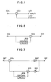
- Fig. 1 shows the configuration of a conventional floating point arithmetic adder which performes floating point arithmetic of a finite word length digital signal.
- the absolute values of two inputs are very different from each other in Fig. 1, e.g., when the absolute value of a first input 1 is much smaller than that of a second input 2.
- the value of the first input 1 is inputted from an input terminal 401
- the value of the second input 2 is inputted from an input terminal 402.
- Under such conditions under flow of the first value is caused, namely, some amount of value of the first input 1 is omitted at the adder 403, thereby outputting a value which includes some amount of error to an output terminal 404.
- the floating point arithmetic adder shown in Fig. 1 suffers from problems about the accuracy in floating point adding operation when the absolute values of two inputs are greatly different from each other.
- the following two examples is related to such problems about the accuracy in floating point adding operation.
- Fig. 2 shows the configuration of a conventional integrator as a first example. Even in this case, when the absolute value of an input from an input terminal 501 is greatly smaller than that of a value of a memory circuit 503, the under flow sometimes occurs.
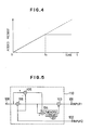
- Figure 4 shows an output of the integrator when a constant value is continuously inputted, in which the axis of abscissa shows time t, and the axis of ordinate shows the output of the integrator. In the period from time 0 to time t1 of Fig. 4, the absolute value of the memory circuit 503 in the integrator of Fig. 2 is not so larger than that of the input value. Thus, the fatal under flow is not caused.
- the floating point adder 502 outputs the floating point added result without fatal under flow, so that the value of the memory circuit 503 in the integrator proportionally increases in accordance with time.
- the under flow is caused from a certain time.
- the value of the memory circuit 503, which is the output of the integrator, after time t1 is not changed because of the under flow, thereby holding it at a constant value.
- the difference between the constant value and an ideal value of the output of the integrator designated by dotted line becomes large in accordance with time, and the accumulated error caused by the under flow becomes an infinite value after an infinite time has passed, thereby greatly reducing the accuracy of the integrator.
- Fig. 3 shows the configuration of a second order loop filter often used in a conventional PLL(Phase Locked Loop). Even in this case, when the absolute value of an input from an input terminal 601 is greatly smaller than that of a value of a memory circuit 606, or when coefficients ⁇ 602 and ⁇ 603 of the loop filter are very small, the input is not added exactly in adders 604 and 605, thereby causing under flow.
- the integrator, the loop filer, etc. should have an adequate accuracy.
- the under flow is caused when the difference between the absolute values of the two inputs is very large.
- an object of the present invention is to provide an adding apparatus which performs the adding operation of the two floating point inputs, in which the under flow can be prevented even when the difference between the absolute values of the two inputs is large, thereby obtaining an operating result having a high accuracy.
- the present invention resides in an adding apparatus for adding first and second input values at any time in which the first input value is smaller than the second input value, said adding apparatus comprising memory means for memorizing an under flow component, first adding means for adding the first input value and a value outputted from the memory means, second adding means for adding the second input value and an output value of the first adding means, first subtracting means for subtracting the second input value from an output value of the second adding means, and means for comparing the output value of the first adding means and an output value of the first subtracting means, whereby the output value of the first adding means is memorized in the memory means by the output of the comparing means.
- the first input value and the output value from the memory means for memorizing the under flow component are added by the first adding means.
- the output value of the first adding means and the second input value are added by the second adding means.
- the output value of the second adding means and the second input value are compared with each other by the comparing means. By this comparison, it can be judged whether or not the first and second input values are added to each other. If the two input values are not added to each other, an amount to be added is accumulatively added to the memory means. This accumulated value is added to the first input value by the first adding means. By such an operation, even when the under flow is caused, the amount for the under flow is accumulatively added, thereby providing an adding apparatus having a high accuracy with very little under flow.
- Fig. 5 shows the configuration of an adding apparatus in accordance with one embodiment of the present invention.
- Fig. 5 shows the configuration of the adding apparatus for providing such an operation.
- Input values of inputs 1 and 2 are inputted to an adding apparatus 110 from input terminals 101 and 102, respectively.
- the input values of the inputs 1 and 2 are represented by floating points.
- the value having the smaller absolute value in comparison with the input terminal 102 is inputted to the input terminal 101.
- value 0.001 is inputted from the input 1
- value 1000 is inputted from the input 2 in the following description.
- the value 0.001 from the input 1 is added to the value memorized in a memory circuit 107 by an adder 103.
- An output value of the adder 103 is inputted to a subtracter 104 and an adder 106.
- This output value is inputted to the subtracter 104, and is subtracted from the output 0.001 from the adder 103.
- value 0.001 is inputted to the memory circuit 107.
- the value 0.001 is outputted from the memory circuit 107, and is added to the next value inputted from the input terminal 101 by the adder 103.
- the subtracter 105 subtracts the value of the input 2 from the output of the adder 106, and outputs the subtracted result to the subtracter 104.
- the subtracter 104 subtracts the output value of the subtracter 105 and the output value of the adder 103.
- the output value of the subtracter 104 constitutes under flow component and is memorized in the memory circuit 107. At the time of the next adding operation, the value from the input 1 and the output value from the memory circuit 107 are added to each other by the adder 103. Accordingly, the accumulated sum of the under flow value is added in the next adding operation at adder 106.
- the adder 106 adds the values from the inputs 1 and 2 without under flow.
- the subtracter 105 subtracts the value of the input 2 from the output of the adder 106, outputting the value of the input 1 to the subtracter 104.
- the subtracter 104 subtracts the output of the subtracter 105 from the output of the adder 103. Namely, the same values are subtracted from each other so that value 0 is inputted to the memory circuit 107. Thus, the content of the memory circuit 107 is 0.
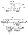
- FIG. 6 shows an embodiment of an integrator using the adding apparatus of the present invention.
- a block portion 502′ of Fig. 6 corresponds to the adder 502 of Fig. 2.
- An input signal is inputted to an input terminal 201 connected to an adder 202.
- the adder 202 is connected to a subtracter 203 and an adder 204.
- the adder 204 is connected to an output terminal 208, a memory circuit 207 and a subtracter 205.
- An output of the memory circuit 207 is supplied to the adder 204.
- the subtracter 205 subtracts the output of the memory circuit 207 from an output of the adder 204, and outputs the subtracted result to the subtracter 203.
- the subtracter 203 subtracts the output of the subtracter 205 from the output of the adder 202, and outputs the subtracted result to the memory circuit 206.
- the input 1 shown in Fig. 5 corresponds to the input terminal 201
- the input 2 corresponds to the output value of the memory circuit 207.
- this situation corresponds to the region after time t1 in Figs. 8 and 9.
- the conventional added result is not changed and becomes constant after time t1 as shown in Fig. 4.
- the added result increases stepwise after time t1 as shown in Fig. 8.
- a stepwise horizontal portion corresponds to a state in which the under flow is caused in the adder 204 of Fig. 6.
- the value of the memory circuit 206 corresponds to a proportionally increasing portion having a constant inclination in the region after time t1 of Fig. 9.
- Fig. 7 shows an embodiment of a loop filter using the adding apparatus of the present invention.
- block portions 604′ and 605′ correspond to adders 604 and 605 of Fig. 3, respectively.
- An input terminal 301 is connected to coefficient multipliers 302 and 303.
- the coefficient multiplier 302 is connected to an adder 304 connected to a subtracter 305 and an adder 306.
- the subtracter 305 is connected to a memory circuit 312 connected to an adder 304.
- the coefficient multiplier 303 is connected to an adder 307 connected to a subtracter 308 and an adder 309.
- the subtracter 308 is connected to a memory circuit 313 connected to the adder 307.
- the adder 309 is connected to a subtracter 310, a memory circuit 314 and the adder 306.
- the subtracter 310 subtracts an output of the memory circuit 314 from an output of the adder 309, and outputs the subtracted result to the subtracter 308.
- the subtracter 308 subtracts an output of the subtracter 310 from an output of the adder 307, and outputs the subtracted result to the memory circuit 313.
- Outputs of the adders 304 and 309 are inputted to the adder 306, and the added input is outputted to an output terminal 315.
- the subtracter 311 subtracts the output of the adder 309 from an output of the adder 306, and outputs the subtracted result to the subtracter 305.
- the subtracter 305 subtracts the output of the subtracter 311 from the output of the adder 304, and outputs the subtracted result to the memory circuit 312.
- the adding operation can be performed with little under flow with respect to the adders 306 and 309 in the loop filter of Fig. 7 even when the absolute value of an input is sufficiently smaller than that of a value of the memory circuit 314, thereby providing a loop filter having a high accuracy.
- the under flow amount in the adding operation can be again added later by using memory means for memorizing an under flow amount accumulatively added even when the absolute values of the two inputs are greatly different from each other. Accordingly, the adding operation with less under flow can be performed, thereby providing the calculated result having a high accuracy.
Landscapes
- Engineering & Computer Science (AREA)
- General Physics & Mathematics (AREA)
- Physics & Mathematics (AREA)
- Pure & Applied Mathematics (AREA)
- Computational Mathematics (AREA)
- Theoretical Computer Science (AREA)
- Mathematical Analysis (AREA)
- Mathematical Optimization (AREA)
- Computing Systems (AREA)
- General Engineering & Computer Science (AREA)
- Nonlinear Science (AREA)
- Complex Calculations (AREA)
- Studio Circuits (AREA)
- Feedback Control In General (AREA)
- Measuring Volume Flow (AREA)
Applications Claiming Priority (2)
| Application Number | Priority Date | Filing Date | Title |
|---|---|---|---|
| JP327176/87 | 1987-12-25 | ||
| JP62327176A JPH01169627A (ja) | 1987-12-25 | 1987-12-25 | 高精度加算装置 |
Publications (2)
| Publication Number | Publication Date |
|---|---|
| EP0322520A2 true EP0322520A2 (de) | 1989-07-05 |
| EP0322520A3 EP0322520A3 (de) | 1991-07-03 |
Family
ID=18196157
Family Applications (1)
| Application Number | Title | Priority Date | Filing Date |
|---|---|---|---|
| EP19880116468 Withdrawn EP0322520A3 (de) | 1987-12-25 | 1988-10-05 | Hochgenauigkeitsaddiergerät |
Country Status (3)
| Country | Link |
|---|---|
| US (1) | US4931979A (de) |
| EP (1) | EP0322520A3 (de) |
| JP (1) | JPH01169627A (de) |
Cited By (2)
| Publication number | Priority date | Publication date | Assignee | Title |
|---|---|---|---|---|
| EP0738960A3 (de) * | 1995-04-18 | 1997-01-15 | Motorola Inc | Verfahren und Gerät zur Reduzierung von Abrundungsfehlern beim Evaluieren von binären Fliesskommapolynomialen |
| US5648924A (en) * | 1995-04-18 | 1997-07-15 | Motorola, Inc. | Method and apparatus for finding arctangents |
Families Citing this family (2)
| Publication number | Priority date | Publication date | Assignee | Title |
|---|---|---|---|---|
| JPH03257619A (ja) * | 1990-03-08 | 1991-11-18 | Matsushita Electric Ind Co Ltd | デジタル演算回路 |
| JPH1055352A (ja) * | 1996-08-08 | 1998-02-24 | Fuji Xerox Co Ltd | 浮動小数点数累積加算装置 |
Family Cites Families (3)
| Publication number | Priority date | Publication date | Assignee | Title |
|---|---|---|---|---|
| SE440300B (sv) * | 1983-11-24 | 1985-07-22 | Ellemtel Utvecklings Ab | Forfarande for att i en samplad signal kompensera for trunkeringsfel samt anordning for utforande av forfarandet |
| JPS6125245A (ja) * | 1984-07-12 | 1986-02-04 | Nec Corp | 丸め処理回路 |
| US4758972A (en) * | 1986-06-02 | 1988-07-19 | Raytheon Company | Precision rounding in a floating point arithmetic unit |
-
1987
- 1987-12-25 JP JP62327176A patent/JPH01169627A/ja active Pending
-
1988
- 1988-08-26 US US07/236,902 patent/US4931979A/en not_active Expired - Lifetime
- 1988-10-05 EP EP19880116468 patent/EP0322520A3/de not_active Withdrawn
Non-Patent Citations (2)
| Title |
|---|
| COMMUNICATIONS OF THE ACM, vol. 13, no. 6, June 1970, pages 361-362; P. LINZ: "Accurate floating-point summation" * |
| COMMUNICATIONS OF THE ACM, vol. 14, no. 11, November 1971, pages 731-736, Association for Computing Machinery, Inc.; M.A. MALCOLM: "On accurate floating-point summation" * |
Cited By (2)
| Publication number | Priority date | Publication date | Assignee | Title |
|---|---|---|---|---|
| EP0738960A3 (de) * | 1995-04-18 | 1997-01-15 | Motorola Inc | Verfahren und Gerät zur Reduzierung von Abrundungsfehlern beim Evaluieren von binären Fliesskommapolynomialen |
| US5648924A (en) * | 1995-04-18 | 1997-07-15 | Motorola, Inc. | Method and apparatus for finding arctangents |
Also Published As
| Publication number | Publication date |
|---|---|
| JPH01169627A (ja) | 1989-07-04 |
| EP0322520A3 (de) | 1991-07-03 |
| US4931979A (en) | 1990-06-05 |
Similar Documents
| Publication | Publication Date | Title |
|---|---|---|
| US6061410A (en) | Frequency ratio estimation arrangement and method thereof | |
| EP0196825B1 (de) | Massstabeinstellungsanordnung mit Ausgleichung der Abbrechungsfehler | |
| EP0209049B1 (de) | Verarbeitungsschaltung, fähig zum Erhöhen des Akkumulationsdurchsatzes | |
| US20090304135A1 (en) | Synchronous clock generation apparatus and synchronous clock generation method | |
| US3749895A (en) | Apparatus for suppressing limit cycles due to quantization in digital filters | |
| EP0396746B1 (de) | Bildempfängersteuerung | |
| JP2957183B2 (ja) | 巡回型ディジタルフィルタ | |
| EP0322520A2 (de) | Hochgenauigkeitsaddiergerät | |
| US5253052A (en) | Apparatus for detecting relative motion between contents of successive fields of a video signal | |
| EP0195482A1 (de) | Digitaler rekursiver Filter ersten Grades für Videosignale | |
| JPH0125444B2 (de) | ||
| KR100290194B1 (ko) | 무한 임펄스 응답 고스트 제거 시스템 | |
| US5311314A (en) | Method of and arrangement for suppressing noise in a digital signal | |
| EP0702290B1 (de) | Digitale Divisionseinrichtung mit einer Nachschlagetafel | |
| US5832003A (en) | Video error/distortion checker | |
| JPH08172343A (ja) | Iir型ディジタルフィルタの構成方法 | |
| US7411527B2 (en) | Noise shaping quantizer | |
| US5210709A (en) | Digital filter for removing dc components | |
| US7352749B2 (en) | Device for checking numbers and method for checking numbers | |
| JPH0732347B2 (ja) | 巡回形デイジタルフイルタ | |
| KR0124993B1 (ko) | 샘플링된 비디오 신호에서 수평 동기신호의 검출시기 오차 보정장치 및 그 방법 | |
| KR0134463B1 (ko) | 개선된 벡터 제한 방법(improved method for limiting vector) | |
| JP3559599B2 (ja) | 信号処理装置 | |
| JPH10107589A (ja) | デジタルフィルタ | |
| JPH0757012B2 (ja) | ゴースト除去装置 |
Legal Events
| Date | Code | Title | Description |
|---|---|---|---|
| PUAI | Public reference made under article 153(3) epc to a published international application that has entered the european phase |
Free format text: ORIGINAL CODE: 0009012 |
|
| 17P | Request for examination filed |
Effective date: 19881005 |
|
| AK | Designated contracting states |
Kind code of ref document: A2 Designated state(s): DE FR GB |
|
| PUAL | Search report despatched |
Free format text: ORIGINAL CODE: 0009013 |
|
| AK | Designated contracting states |
Kind code of ref document: A3 Designated state(s): DE FR GB |
|
| 17Q | First examination report despatched |
Effective date: 19940323 |
|
| STAA | Information on the status of an ep patent application or granted ep patent |
Free format text: STATUS: THE APPLICATION IS DEEMED TO BE WITHDRAWN |
|
| 18D | Application deemed to be withdrawn |
Effective date: 19941005 |