EP0321920A2 - Système centrifuge de commande avec deux processeurs - Google Patents
Système centrifuge de commande avec deux processeurs Download PDFInfo
- Publication number
- EP0321920A2 EP0321920A2 EP88121279A EP88121279A EP0321920A2 EP 0321920 A2 EP0321920 A2 EP 0321920A2 EP 88121279 A EP88121279 A EP 88121279A EP 88121279 A EP88121279 A EP 88121279A EP 0321920 A2 EP0321920 A2 EP 0321920A2
- Authority
- EP
- European Patent Office
- Prior art keywords
- motor
- processor
- instrument
- processors
- source
- Prior art date
- Legal status (The legal status is an assumption and is not a legal conclusion. Google has not performed a legal analysis and makes no representation as to the accuracy of the status listed.)
- Granted
Links
Images


Classifications
-
- H—ELECTRICITY
- H02—GENERATION; CONVERSION OR DISTRIBUTION OF ELECTRIC POWER
- H02P—CONTROL OR REGULATION OF ELECTRIC MOTORS, ELECTRIC GENERATORS OR DYNAMO-ELECTRIC CONVERTERS; CONTROLLING TRANSFORMERS, REACTORS OR CHOKE COILS
- H02P5/00—Arrangements specially adapted for regulating or controlling the speed or torque of two or more electric motors
- H02P5/46—Arrangements specially adapted for regulating or controlling the speed or torque of two or more electric motors for speed regulation of two or more dynamo-electric motors in relation to one another
- H02P5/50—Arrangements specially adapted for regulating or controlling the speed or torque of two or more electric motors for speed regulation of two or more dynamo-electric motors in relation to one another by comparing electrical values representing the speeds
-
- B—PERFORMING OPERATIONS; TRANSPORTING
- B04—CENTRIFUGAL APPARATUS OR MACHINES FOR CARRYING-OUT PHYSICAL OR CHEMICAL PROCESSES
- B04B—CENTRIFUGES
- B04B9/00—Drives specially designed for centrifuges; Arrangement or disposition of transmission gearing; Suspending or balancing rotary bowls
- B04B9/10—Control of the drive; Speed regulating
Definitions
- This invention relates to a control system for a centrifuge instrument and, in particular, to a control system having a control architecture that utilizes two processors.
- a centrifuge rotor is a relatively massive member adapted to expose a sample of a liquid to a centrifugal force field. To create the force field the rotor is rotated to a relatively high rotational speed. However, if the rotational speed to which the rotor is accelerated is too high the possibility exists that the rotor may fail catastrophically. In order to prevent this failure from occurring most centrifuge instruments utilize a microprocessor-based speed control system having a single processor therein to limit the maximum rotational speed to which the rotor is subjected to a value which is well below the speed of catastrophic failure of the rotor.
- microprocessor-based systems though not specifically applied to a centrifuge instrument, are disclosed in the turbine control systems of United States Patents 4,635,209 (Hwang et al.), 4,494,207 (Chang et al.), 4,494,208 (Chang) and 4,319,320 (Sato et al.).
- microprocessor-based centrifuge instrument control system configured with multiple processors such that each of the processors may independently perform a given control function and to implement such a system in an economically practical manner.
- the present invention relates to a control system for a centrifuge instrument having a motor with a shaft, the motor being connected to a source of energy.
- the motor is operative to rotate the shaft to a predetermined rotational speed.
- a tachometer is associated with the shaft and is operative to generate a signal representative of the actual rotational speed thereof.
- the control system includes a programmable controller operative to provide a predetermined set of instrument control functions including the function of conditionally coupling of the source to the motor.
- the programmable controller has a first and a second processor therein, the processors being configured in a master-slave relationship for some predetermined subset of the instrument control functions during the execution of which the slave operates under the direction of the master to effect that subset of control functions.
- each of the processors is independently responsive to the speed signal from the tachometer and is independently capable of controlling the additional instrument control function of conditionally coupling the source to the motor.
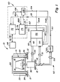
- FIG. 1 Shown in Figure 1 is a stylized pictorial representation of a centrifuge instrument generally indicated by reference character 10 embodying the teachings of the present invention.
- the instrument 10 includes a framework schematically indicated at 12.
- the framework 12 supports a chamber, or bowl, 14.
- the interior of the bowl 14 defines a generally enclosed chamber 16 in which a rotating element, or rotor, 18 may be received. Access to the chamber 16 on the interior of the bowl 14 is afforded through a lid or door 20.
- the bowl 14 may be provided with suitable evaporator coils, not shown, in the event that it is desired to refrigerate the bowl 14 and the rotor 18 and its contents.
- One or more energy containment members, or guard rings, 22 is carried by the framework 12.
- the guard ring 22 is arranged concentrically with respect to the bowl 14 and serves to absorb the kinetic energy of the rotor 18 or fragments thereof should a catastrophic failure of the rotor 18 occur.
- the guard ring 22 is movably mounted within the framework 12, as schematically indicated by the rollers 24, to permit free rotation thereof to absorb the rotational component of the energy of the rotor fragments. It is important to absorb the energy of the rotor and to contain the possible fragments thereof which, if permitted to exit the instrument, may cause injury to an operator.
- the motor 30 is connected to a source of electrical energy through a DC power drive generally indicated by reference character 32.
- the motor 30 includes a drive shaft 34 that projects into the chamber 16.
- the upper end of the shaft 34 is provided with a mounting spud 36 which receives the rotor 18.
- the motor 30 takes the form of a multiphase brushless DC motor such as that manufactured and sold by Electric Indicator Company Incorporated of Norwalk Connecticut.
- the power drive 32 is associated with the motor 30 provides a controlled electric current to the motor 32 over lines 44.
- the power drive 32 includes a variable voltage source 46, a switching matrix 48 and a commutation control 50.
- a typical example of a power drive for a brushless DC motor is illustrated in United States Patent 3,783,359 (Malkiel), which is hereby incorporated by reference.
- the motor 30 includes a plurality of Hall Effect sensors (not shown), the outputs of which are provided over the lines 51 to the commutation control 50 of the drive 32.
- a tachometer generally indicated by reference character 52 is arranged to monitor the rotational speed (i.e., angular velocity) of the shaft 34 and thereby the rotational speed (i.e., angular velocity) of the rotor 18.
- the tachometer 52 is implemented using the outputs of the Hall Effect sensors which are applied over the lines 51A to a logic network 52L.
- the Hall Effect outputs are exclusively OR-ed in the logic 52L.
- the electrical signal produced by the logic 52L is carried on a line 53.
- the signal on the line 53 provides an indication of the rotational speed (angular velocity) of the shaft 34 and the rotor 18 mounted thereon. This signal on the line 53 is referred to as the tachometer signal.
- the elements 46 and 50 of the power drive 32 are responsive to an enable signal derived in a manner to be described and applied to these elements over lines 54A and 54B respectively.
- the enable signal on the line 54A applies a voltage from the variable voltage source 46 to the switching matrix 48.
- the enable signal on the line 54B enables the normal commutation sequence of the switching matrix 48 via the commutation control 50.
- the signal applied over the lines 54A, 54B functions to conditionally coupled the source 46 to the motor 30.
- a programmable controller 60 having a control architecture in accordance with the present invention is responsive in a manner to be described to the tachometer signal on the line 53 representative of the rotor speed.
- the programmable controller 60 outputs a motor current control signal on a line 62 to the motor power drive 32.
- a status line 63 is provided between the motor power drive 32 and the programmable controller 60.
- the motor power drive 32 responds to the signal on the line 62 to modify appropriately the level of current applied to the motor 30 and thereby control the torque output of the motor 30 and thus the rotational speed of the shaft 34 and the rotor 18 thereon.
- the programmable controller 60 also generates the enable signal carried on the lines 54A and 54B to carry out the instrument control function of conditionally coupling the source 46 to the motor 30.
- An operator control panel 68 communicates with the programmable controller 60 over a line 70 and permits an operator to enter desired run parameters, including a requested rotational speed (angular velocity) for the rotor. The panel also displays
- the programmable controller 60 is implemented by an arrangement comprising a first and a second processor 72 and 74 respectively.
- the processors 72, 74 are arranged in a architecture believed best described as a hybrid distributed processing system.
- the first processor 72 is implemented by a device manufactured and sold by Motorola as model number MC6809 while the second processor is manufactured and sold by Motorola as model MC6803.
- the processors 72 and 74 communicate with each other over a multibit link 78.
- the overall task of controlling the centrifuge instrument 10 is divided between the first and second processors 72 and 74, respectively. As will be seen generating the enable signal on the line 54 requires both processors 72, 74. Removal of the enable signal can be accomplished independently by either processor.
- the first processor 72 is directly connected via a line 80 on the processor board to the line 70 from the operator panel 68.
- the first processor 72 is responsible to superintend the performance of the overall set of instrument control functions necessary to the operation of the instrument 10.
- the processor 72 serves to receive the operator selected set points (including rotational speed) and outputs of this set point information in a suitable form to the second processor 74 over the link 78.
- the first processor 72 also receives control status information from the second processor 74 over the link 78 and also sends status information for display on the operator panel 68.
- information regarding the speed of the shaft 34 is input to the processor 72 on a line 82A on the processor board.
- the line 82A is connected to the line 53 carrying the tachometer signal. From the standpoint of instrument control functions the processor 72 also serves to remove the enable signal applied to the power drive 32 on the lines 54A and 54B whereby the source 46 is conditionally coupled to the motor 30.
- the second processor 74 is, in the normal operation of the instrument, connected in what may be described as a slave relationship to the first processor 72. As such the second processor 74 receives the set point information and executes the actions necessary to carry out some predetermined subset of the instrument control functions. In addition the second processor 74 acts independently of and co-equally with the first processor 72 to remove the enable signal on the lines 54A and 54B which effects the additional instrument control function of conditionally coupling the source 46 to the motor 30. To this end the second processor 74 is also supplied with the tachometer signal on the line 53. This information is applied to the second processor 74 via a line 82B connected to the line 53.
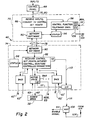
- the first processor 72 receives an operator input through the operator control panel 68 and operates on the same, as indicated at block 88.
- the block 88 receives the inputs and converts them to control setpoints. These control setpoints are passed by the first processor 72 over the multibit link 78 to the second processor 74 using suitable network software 90.
- the control setpoints are operated on by the second processor 74, as indicated at block 92, to effect a predetermined subset of the total set of appropriate instrument control functions.
- the subset of instrument control functions is indicated diagramatically by the blocks 94A, 94B ... 94N.
- the second processor 74 generates status information on each of the set of control functions 94A through 94N, as shown at the block 96, and reports the same to the first processor via the network software 90 and the link 78.
- one of the set of instrument control functions is the instrument motor drive control function as indicated in the block 94A.
- This function 94A generates the motor current control signal to the power drive 32 over the line 62.
- Status information from the power drive 32 is provided to the second processor 74 on the status line 63. Similar (i.e., control and status lines) are provided for the others of the subset of instrument control functions, as indicated by the lines 62′, 63′, respectively.
- processors 72 and 74 act substantially in a master/slave relationship for the implementation of the predetermined subset of the total set of the instrument control functions.
- both the first processor 72 and the second processor 74 are simultaneously active and each is independently able to execute the additional instrument control function of conditionally coupling the source 46 to the motor 30.
- the block 98 uses the control set points derived from the block 88 to set a speed threshold in functional block 99.
- the threshold itself corresponds to the rotational speed as selected by an operator plus some predetermined margin (e.g., four hundred rpm).
- the speed threshold is used in a manner to be described.
- the first processor 72 in the block 100, verifies whether the communication link 78 between the first and second processor is operative or, in one instance, whether the instrument is indeed decelerating the load when appropriate.
- the first processor 72 receives the tachometer signal on the lines 53, 82A.
- the processor 72 After verifying conditions are suitable for a run, asserts a logic true on its enable line 106. If the tachometer signal indicates a speed that exceeds the speed threshold, as determined in the block 102, a fault condition on the line 103 is established. In the block 100 a determination is made as to whether the appropriate deceleration is occurring or whether the communications system is operational.
- the results of the determinations made in the block 100 and the determinations made in the block 102 are logically OR-ed in the block 104 to produce a logical false on a line 106.
- the signal on line 106 is applied to a logic AND hardware network 108.
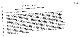
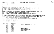
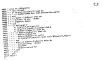
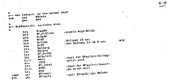
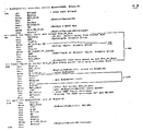
- the generation of the threshold value in the block 99 is set forth on page A-2 of the listing. Entry to the block 99 may be made from one of four routines (STrap5s, STrap5, STrap 67 or STrap8). In general these four routines are implemented when either a change of speed set point or a stop of rotor is requested. In any event, from whatever routine the threshold block 99 is entered, the listing on page A-2 generates the necessary threshold value.
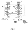
- the block 102 basically performs a comparison (termed “HiTrap” in the listing) between the period of the tachometer signal on the line 53, 82A with the period of a reference signal that corresponds to the threshold signal.
- the comparison is actually performed in hardware, such as a timer (an MC6840 timer) that is set with a value corresponding to the period of the reference signal.
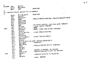
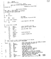
- Pages A-1, A-3, and A-4 set forth the code whereby the timer is loaded. The timer begins decrementing on each falling edge of the tachometer signal.
- the result of the comparison is insulated from transients by the portion of the code set out on pages A-10 and A-11 of the listing.
- This portion of the code requires that the fault be established under a predetermined number of times (eight, in the listing) before the fault is asserted on the line 103.
- the speed comparison is acceptable if the period of the tachometer signal is greater than the period of the reference signal.
- the setting of the fault condition on line 103 is accomplished at page A-9 of the listing.
- the logical OR of the flag "HiTrap" (generated by the block 102 in response to the tachometer signal as discussed above) and the flags generated by the block 100 is formed by the code set forth on page A-9 of the listing that actually implements the block 104.
- the setting of the logical false on the line 106 is accomplished by the code noted on that same page of the listing.
- the instrument control function of conditionally coupling the source to the motor is executed by a subroutine 110 within the motor drive control block 94A.
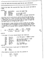
- a listing of the relevant portions of the program for the second processor 74, in assembly language for an MC6903 processor, is attached as pages A-12 through A-15 of the Appendix. Similar to the processor 72, when a run start is requested the processor 74, after verifying that conditions are suitable for a run, asserts a logic true in its enable line 116. As seen in Figure 3B and at pages A-12 and A-13 of the listing the block 109 converts the tachometer signal on the lines 53, 82B provide a representation of the rotational speed of the shaft.
- the block 110 (page A-13) performs a comparison with a speed setpoint (as derived via the network) to determine whether the shaft speed is within acceptable control limits. If the speed is within the control limit the processor 74 continues with normal control. However, if the comparison indicates that the speed of the shaft is outside the control limit the line 111 is asserted. As seen at page A-13 of the listing, the actual code executed is a jump to a subroutine "sc-func 24." In Figure 3B, this is indicated by a signal on the line 111 to the network 114.
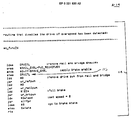
- the block 92 performs a similar determination in subroutine block 112 for each of the other instrument control functions 94B through 94N. If any one of the control functions is beyond the acceptable control range a particular bit in the byte "Faults" is set. The code on page A-15 of the listing implements an examination of the byte "Faults.” If any flag bit in the byte has been set the branch to the subroutine "sc-func 24" is asserted on the line 113. If no flag is set, normal control continues.
- the results of the determinations made in the blocks 110, and 112 are logically OR-ed in the block 114 to produce a logical false on a line 116.
- Setting the logical false on the line 116 is accomplished by the subroutine "sc-func 24" set forth at page A-14. This code implements the block 114.
- the signal on the line 116 is applied to network 108.
- the motor drive enable signal carried on the 54 (which splits into lines 54A and 54B) is asserted only if the inputs on the lines 106 and 116 are logical true. If either of the lines 106 or 116 is logical false then the motor drive enablement signal is not asserted.
- both the first processor 72 and the second processor 74 are each responsive to the tachometer signal and both are simultaneously active and independently capable of removing the enable signal. Both the first processor and the second processor are thus each independently capable of carrying out the instrument control function of conditionally coupling the energy source 46 to the motor 30. So long as the states of the signals on the lines 106, 116 indicate that the instrument's operation is acceptable, energy is applied to the motor. If the state of either line changes the motor is decoupled from the source. The decoupling can be independently controlled by either processor.
Landscapes
- Engineering & Computer Science (AREA)
- Power Engineering (AREA)
- Centrifugal Separators (AREA)
- Programmable Controllers (AREA)
- Control Of Electric Motors In General (AREA)
Applications Claiming Priority (2)
| Application Number | Priority Date | Filing Date | Title |
|---|---|---|---|
| US07/137,097 US4903191A (en) | 1987-12-23 | 1987-12-23 | Centrifuge control system having dual processors |
| US137097 | 2002-05-01 |
Publications (3)
| Publication Number | Publication Date |
|---|---|
| EP0321920A2 true EP0321920A2 (fr) | 1989-06-28 |
| EP0321920A3 EP0321920A3 (en) | 1990-11-28 |
| EP0321920B1 EP0321920B1 (fr) | 1993-09-29 |
Family
ID=22475826
Family Applications (1)
| Application Number | Title | Priority Date | Filing Date |
|---|---|---|---|
| EP88121279A Expired - Lifetime EP0321920B1 (fr) | 1987-12-23 | 1988-12-20 | Système centrifuge de commande avec deux processeurs |
Country Status (6)
| Country | Link |
|---|---|
| US (1) | US4903191A (fr) |
| EP (1) | EP0321920B1 (fr) |
| JP (1) | JPH0612955B2 (fr) |
| CA (1) | CA1295010C (fr) |
| DE (1) | DE3884587T2 (fr) |
| IE (1) | IE67278B1 (fr) |
Cited By (2)
| Publication number | Priority date | Publication date | Assignee | Title |
|---|---|---|---|---|
| US5649893A (en) * | 1996-05-22 | 1997-07-22 | Hitachi Koki Co., Ltd. | Centrifugal apparatus having series-implemented protection means |
| DE10163010B4 (de) * | 2001-04-25 | 2007-01-25 | Siemens Ag | Verfahren und Einrichtung zur sicheren Überwachung der Drehzahl einer elektrischen Maschine |
Families Citing this family (13)
| Publication number | Priority date | Publication date | Assignee | Title |
|---|---|---|---|---|
| JPH0776736B2 (ja) * | 1988-09-28 | 1995-08-16 | 富士重工業株式会社 | 車輌診断システム |
| US5235864A (en) * | 1990-12-21 | 1993-08-17 | E. I. Du Pont De Nemours And Company | Centrifuge rotor identification system based on rotor velocity |
| JPH07239317A (ja) * | 1994-02-25 | 1995-09-12 | Shimadzu Corp | 電気泳動装置 |
| JP3384134B2 (ja) * | 1994-08-17 | 2003-03-10 | 日立工機株式会社 | 遠心機に於るロータの過回転防止制御装置 |
| US5721676A (en) * | 1995-10-18 | 1998-02-24 | Sorvall Products, L.P. | Centrifuge data communications system |
| DE19632965A1 (de) * | 1996-08-16 | 1998-02-19 | Sigma Laborzentrifugen Gmbh | Steuerungssystem für eine Laborzentrifuge |
| JP3879360B2 (ja) * | 2000-03-17 | 2007-02-14 | 日立工機株式会社 | 遠心機 |
| US6368265B1 (en) * | 2000-04-11 | 2002-04-09 | Kendro Laboratory Products, L.P. | Method and system for energy management and overspeed protection of a centrifuge |
| US6507161B2 (en) | 2000-04-14 | 2003-01-14 | The Western States Machine Company | Centrifuge motor control |
| US7458928B2 (en) * | 2002-06-13 | 2008-12-02 | Kendro Laboratory Products, Lp | Centrifuge energy management system and method |
| US6943509B2 (en) * | 2003-07-09 | 2005-09-13 | Kendro Laboratory Products, Lp | Rotor speed control device and method |
| US7396324B2 (en) * | 2003-10-17 | 2008-07-08 | Hitachi Koki Co., Ltd. | Centrifugal separator with first and second control panels |
| US8511305B2 (en) * | 2007-10-29 | 2013-08-20 | Smiths Medical Asd, Inc. | Redundant power control for respiratory system heaters |
Family Cites Families (21)
| Publication number | Priority date | Publication date | Assignee | Title |
|---|---|---|---|---|
| US3262040A (en) * | 1963-09-23 | 1966-07-19 | Sorvall Inc Ivan | Speed control system for centrifuge motors and the like |
| JPS5323920U (fr) * | 1976-08-09 | 1978-02-28 | ||
| US4133642A (en) * | 1978-03-10 | 1979-01-09 | Terumo Corporation | Pipetting apparatus for automatic analyzer |
| JPS54152767A (en) * | 1978-05-24 | 1979-12-01 | Hitachi Ltd | Process accomodation control method |
| DE3003291C2 (de) * | 1980-01-30 | 1983-02-24 | Siemens AG, 1000 Berlin und 8000 München | Zweikanalige Datenverarbeitungsanordnung für Eisenbahnsicherungszwecke |
| US4367043A (en) * | 1980-05-05 | 1983-01-04 | Leland Stanford Junior University | Method and means for delivering liquid samples to a sample scanning device |
| US4631722A (en) * | 1982-02-11 | 1986-12-23 | Zf-Herion-Systemtechnik Gmbh | Electronic controller for cyclically operating machinery |
| US4494208A (en) * | 1982-04-15 | 1985-01-15 | General Electric Company | Bumpless switching of valve drive in a turbine control system |
| US4494207A (en) * | 1982-04-15 | 1985-01-15 | General Electric Company | Dual turbine controller |
| JPS5915804U (ja) * | 1982-07-20 | 1984-01-31 | 株式会社クボタ | 油圧装置 |
| FR2540685A1 (fr) * | 1983-02-03 | 1984-08-10 | Jeumont Schneider | Interface pour relier un systeme informatique a un dispositif actionneur |
| JPS59158504U (ja) * | 1983-04-12 | 1984-10-24 | マメトラ農機株式会社 | 農用車輪 |
| JPS6182201A (ja) * | 1984-09-29 | 1986-04-25 | Nec Home Electronics Ltd | フエイルセ−フ制御回路 |
| US4635209A (en) * | 1984-10-31 | 1987-01-06 | Westinghouse Electric Corp. | Overspeed protection control arrangement for a steam turbine generator control system |
| JPS61126918A (ja) * | 1984-11-21 | 1986-06-14 | Kawasaki Steel Corp | ル−パ−制御方式 |
| JPS61157284A (ja) * | 1984-12-27 | 1986-07-16 | Fanuc Ltd | 駆動制御装置 |
| US4700117A (en) * | 1985-05-31 | 1987-10-13 | Beckman Instruments, Inc. | Centrifuge overspeed protection and imbalance detection system |
| JPH0426583Y2 (fr) * | 1985-07-26 | 1992-06-25 | ||
| JPS63500437A (ja) * | 1985-08-09 | 1988-02-18 | ベツクマン インスツルメンツ インコ−ポレ−テツド | 遠心分離機用超過速度信号無効装置 |
| JPS6253251A (ja) * | 1985-08-30 | 1987-03-07 | Fuji Heavy Ind Ltd | 無段変速機の制御装置 |
| EP0222047B2 (fr) * | 1985-11-13 | 1994-09-14 | Nec Home Electronics Ltd. | Circuit de commande à l'abri de défaillances |
-
1987
- 1987-12-23 US US07/137,097 patent/US4903191A/en not_active Expired - Lifetime
-
1988
- 1988-12-15 CA CA000586047A patent/CA1295010C/fr not_active Expired - Lifetime
- 1988-12-20 EP EP88121279A patent/EP0321920B1/fr not_active Expired - Lifetime
- 1988-12-20 DE DE88121279T patent/DE3884587T2/de not_active Expired - Lifetime
- 1988-12-21 IE IE382588A patent/IE67278B1/en not_active IP Right Cessation
- 1988-12-22 JP JP63322245A patent/JPH0612955B2/ja not_active Expired - Fee Related
Cited By (2)
| Publication number | Priority date | Publication date | Assignee | Title |
|---|---|---|---|---|
| US5649893A (en) * | 1996-05-22 | 1997-07-22 | Hitachi Koki Co., Ltd. | Centrifugal apparatus having series-implemented protection means |
| DE10163010B4 (de) * | 2001-04-25 | 2007-01-25 | Siemens Ag | Verfahren und Einrichtung zur sicheren Überwachung der Drehzahl einer elektrischen Maschine |
Also Published As
| Publication number | Publication date |
|---|---|
| US4903191A (en) | 1990-02-20 |
| EP0321920A3 (en) | 1990-11-28 |
| IE883825L (en) | 1989-06-23 |
| IE67278B1 (en) | 1996-03-20 |
| DE3884587D1 (de) | 1993-11-04 |
| EP0321920B1 (fr) | 1993-09-29 |
| CA1295010C (fr) | 1992-01-28 |
| JPH027888A (ja) | 1990-01-11 |
| JPH0612955B2 (ja) | 1994-02-16 |
| DE3884587T2 (de) | 1994-01-27 |
Similar Documents
| Publication | Publication Date | Title |
|---|---|---|
| US4903191A (en) | Centrifuge control system having dual processors | |
| CA1268055A (fr) | Systeme de protection contre l'emballement et de detection du desequilibre pour appareil centrifuge | |
| EP1724915B1 (fr) | Processeur de sécurité indépendant pour désactiver des dispositifs de forte puissance | |
| US4827197A (en) | Method and apparatus for overspeed protection for high speed centrifuges | |
| JPH03136694A (ja) | 家庭電気機械の負荷不平衝の検出及び補正方法、洗濯機及びその制御システム | |
| AU2373588A (en) | Out-of-balance control for laundry machine | |
| US3462670A (en) | Centrifuge and means to prevent overdriving its rotor | |
| US5650578A (en) | Energy monitor for a centrifuge instrument | |
| WO1987000770A1 (fr) | Systeme prioritaire sur les signaux de protection contre des survitesses dans un appareil centrifuge | |
| US6879262B1 (en) | Control device for a laboratory centrifuge | |
| US4951210A (en) | Protective apparatus of vehicle microcomputer | |
| US5196772A (en) | Apparatus for fitting tires on wheels | |
| US5739428A (en) | System for speed-controlled balancing the wheel of a motor vehicle | |
| Manual | GV3000/SE Operator Interface Module (OIM) User Guide Version 2.0 | |
| JPH0661484B2 (ja) | 遠心▲ろ▼渦機の運転方法及びその制御装置 | |
| JP2026025168A (ja) | 遠心機 | |
| SU1079543A1 (ru) | Устройство управлени двигательно-движительным комплексом судна с редуктором | |
| JPS58182481A (ja) | Dcモ−タの非常停止装置 | |
| JPH10118529A (ja) | 遠心分離機 | |
| EP0540696A4 (fr) | ||
| JPS63196372A (ja) | 研削盤 | |
| JPH01264573A (ja) | 電力変換装置のリセット回路 | |
| JPS5753262A (en) | Monitor for operation of centrifuge | |
| JPH03186293A (ja) | 遠心脱水機 | |
| JPH0993984A (ja) | 回転体駆動用交流電動機の制御方法および装置 |
Legal Events
| Date | Code | Title | Description |
|---|---|---|---|
| PUAI | Public reference made under article 153(3) epc to a published international application that has entered the european phase |
Free format text: ORIGINAL CODE: 0009012 |
|
| AK | Designated contracting states |
Kind code of ref document: A2 Designated state(s): DE FR GB IT |
|
| PUAL | Search report despatched |
Free format text: ORIGINAL CODE: 0009013 |
|
| AK | Designated contracting states |
Kind code of ref document: A3 Designated state(s): DE FR GB IT |
|
| RHK1 | Main classification (correction) |
Ipc: B04B 9/10 |
|
| 17P | Request for examination filed |
Effective date: 19901109 |
|
| 17Q | First examination report despatched |
Effective date: 19920331 |
|
| GRAA | (expected) grant |
Free format text: ORIGINAL CODE: 0009210 |
|
| AK | Designated contracting states |
Kind code of ref document: B1 Designated state(s): DE FR GB IT |
|
| REF | Corresponds to: |
Ref document number: 3884587 Country of ref document: DE Date of ref document: 19931104 |
|
| ITF | It: translation for a ep patent filed | ||
| ET | Fr: translation filed | ||
| PLBI | Opposition filed |
Free format text: ORIGINAL CODE: 0009260 |
|
| 26 | Opposition filed |
Opponent name: SIGMA LABORZENTRIFUGEN GMBH Effective date: 19940623 |
|
| PGFP | Annual fee paid to national office [announced via postgrant information from national office to epo] |
Ref country code: GB Payment date: 19960926 Year of fee payment: 9 |
|
| APAC | Appeal dossier modified |
Free format text: ORIGINAL CODE: EPIDOS NOAPO |
|
| PLBN | Opposition rejected |
Free format text: ORIGINAL CODE: 0009273 |
|
| STAA | Information on the status of an ep patent application or granted ep patent |
Free format text: STATUS: OPPOSITION REJECTED |
|
| 27O | Opposition rejected |
Effective date: 19970223 |
|
| PG25 | Lapsed in a contracting state [announced via postgrant information from national office to epo] |
Ref country code: GB Free format text: LAPSE BECAUSE OF NON-PAYMENT OF DUE FEES Effective date: 19971220 |
|
| GBPC | Gb: european patent ceased through non-payment of renewal fee |
Effective date: 19971220 |
|
| PGFP | Annual fee paid to national office [announced via postgrant information from national office to epo] |
Ref country code: FR Payment date: 20021127 Year of fee payment: 15 |
|
| PG25 | Lapsed in a contracting state [announced via postgrant information from national office to epo] |
Ref country code: FR Free format text: LAPSE BECAUSE OF NON-PAYMENT OF DUE FEES Effective date: 20040831 |
|
| REG | Reference to a national code |
Ref country code: FR Ref legal event code: ST |
|
| APAH | Appeal reference modified |
Free format text: ORIGINAL CODE: EPIDOSCREFNO |
|
| PG25 | Lapsed in a contracting state [announced via postgrant information from national office to epo] |
Ref country code: IT Free format text: LAPSE BECAUSE OF NON-PAYMENT OF DUE FEES;WARNING: LAPSES OF ITALIAN PATENTS WITH EFFECTIVE DATE BEFORE 2007 MAY HAVE OCCURRED AT ANY TIME BEFORE 2007. THE CORRECT EFFECTIVE DATE MAY BE DIFFERENT FROM THE ONE RECORDED. Effective date: 20051220 |
|
| PGFP | Annual fee paid to national office [announced via postgrant information from national office to epo] |
Ref country code: DE Payment date: 20080131 Year of fee payment: 20 |