EP0321780A2 - Levier à main pour mitigeur monocommande - Google Patents
Levier à main pour mitigeur monocommande Download PDFInfo
- Publication number
- EP0321780A2 EP0321780A2 EP88120412A EP88120412A EP0321780A2 EP 0321780 A2 EP0321780 A2 EP 0321780A2 EP 88120412 A EP88120412 A EP 88120412A EP 88120412 A EP88120412 A EP 88120412A EP 0321780 A2 EP0321780 A2 EP 0321780A2
- Authority
- EP
- European Patent Office
- Prior art keywords
- lever
- hand lever
- head housing
- housing
- jacket
- Prior art date
- Legal status (The legal status is an assumption and is not a legal conclusion. Google has not performed a legal analysis and makes no representation as to the accuracy of the status listed.)
- Granted
Links
Images

Classifications
-
- F—MECHANICAL ENGINEERING; LIGHTING; HEATING; WEAPONS; BLASTING
- F16—ENGINEERING ELEMENTS AND UNITS; GENERAL MEASURES FOR PRODUCING AND MAINTAINING EFFECTIVE FUNCTIONING OF MACHINES OR INSTALLATIONS; THERMAL INSULATION IN GENERAL
- F16K—VALVES; TAPS; COCKS; ACTUATING-FLOATS; DEVICES FOR VENTING OR AERATING
- F16K31/00—Actuating devices; Operating means; Releasing devices
- F16K31/44—Mechanical actuating means
- F16K31/60—Handles
- F16K31/605—Handles for single handle mixing valves
Definitions
- the invention relates to a hand lever actuation device for one-handle mixer valves according to the preamble of claim 1.
- a hand lever is designed as a bracket, two parallel ring arches of the lever arm sliding tangentially through correspondingly shaped openings in the jacket sleeve of the lever head and brought together in the outer region to form a handle.
- the two lever arms are each provided in the area through the wall of the lever head housing with an arc around the center of the pivot axis of the inner lever, so that these arcs are in the user's field of vision.
- the invention has for its object to provide a different design of the lever handle shaped as a bow handle and the lever head housing, while keeping the slimest possible shape of the lever head housing.
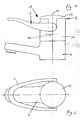
- the engagement mixer valve shown in particular in Figures 1 to 4 consists essentially of a valve housing 4 with connections for cold and hot water, not shown in the drawing, a cartridge housing 5, in which ceramic valve disks are arranged as valve members and in which an inner lever 11 around a Swivel bearing axis 51 pivotable and by one rotation axis 12 is rotatably arranged.
- the hand lever actuating device 1 is formed above the valve housing 4 in a partial area of the cartridge housing 5.
- the hand lever actuation device 1 consists of a lever head housing 2 and a hand lever 3.
- the lever head housing is formed in two parts and consists of a jacket part 21 and a hood 22, while the hand lever 3 is formed in one piece and is positively connected to the inner lever 11, a screw 13 accessible from above being provided for securing.
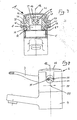
- the jacket part 21 of the lever head housing 2 essentially consists of a cylindrical sleeve on which two opposite windows 211 are formed from the upper end face, the bottom of which each forms one half of a passage opening 23 .
- Corresponding adapters 221 are integrally formed on the hood 22, as is shown in particular in FIGS. 5 and 6 of the drawing.
- the fitting pieces 221 can be pushed into the windows 211, the end faces of the fitting pieces 221 being designed and shaped such that they form the second half of the passage openings 23.
- the hood 22 forms the front cover of the jacket part 21 and closes the windows 211 except for the passage openings 23.
- snap tongues 27 are formed on the hood 22 with which the hood 22 can be locked on the jacket part 21.
- the hand lever 3 as is shown in particular in FIGS. 9 and 10, is produced in one piece using the zinc die-casting method, the arms of the bracket part, which are guided in parallel, being brought tangentially to the cylindrical part of the lever head housing 2.
- a crosspiece 34 is formed, in which the inner lever 11 is received in a form-fitting manner.
- cheeks 32 are formed on both sides, on each of which a pin 31 having a circular cross section is formed perpendicular to the axis of rotation 12 and establish the connection to the bow-shaped part of the hand lever 3.
- the hand lever 3 is pulled down with its cheeks 32 into the vicinity of the fastening screws 52 of the cartridge housing 5 in order to achieve the shortest possible swivel arc for swiveling the hand lever 3 around the swivel bearing axis 51.
- the passage openings 23 therefore have the shape of an annular arc piece 24, as can be seen in particular from FIG. 4.
- the center of the ring arc is formed by the pivot bearing axis 51.
- the cartridge housing 5 is fastened to the valve housing 4 with the valve members and the inner lever 11 with the fastening screws 52.
- the jacket part 21 can then be slipped over the cartridge housing 5 and supported with its end face on the valve housing 4.
- the hand lever 3 is pushed with its transverse web 34 onto the protruding inner lever arm 11, which is approximately square in cross section, and secured with the screw 13.
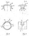
- the hand lever 3 with its pin 31 in the bottom of the Window 211 superimposed.
- the hood with its fitting pieces 221 can be inserted into the windows 211 and locked in the plug-in position with the snap tongues 27, so that the two pins 31 are now each mounted in an arcuate passage opening 23.
- the annular arc 24 is dimensioned so that the hand lever 3 can be brought from its closed position, as shown in Figure 4, by lifting or pivoting about the pivot bearing axis 51 in a position in which the full flow through the mixing valve is released becomes. If, on the other hand, the mixing ratio is to be changed, the hand lever 3 is pivoted about the axis of rotation 12.
- parallel contact surfaces 25 are provided which each has a cheek 32 of the transverse web 34 with an approximately circular end face and thus a positive entrainment of the lever head housing 2 is ensured during the pivoting movement about the axis of rotation 12.
- approximately circular flats 26 are formed on the outside in the area of the passage openings 23, the hand lever 3 being in the area of the introduction into the Lever head housing 2 has appropriately shaped widenings 33.
Landscapes
- Engineering & Computer Science (AREA)
- General Engineering & Computer Science (AREA)
- Mechanical Engineering (AREA)
- Multiple-Way Valves (AREA)
- Sheet Holders (AREA)
- Mechanically-Actuated Valves (AREA)
Priority Applications (1)
| Application Number | Priority Date | Filing Date | Title |
|---|---|---|---|
| AT88120412T ATE82050T1 (de) | 1987-12-19 | 1988-12-07 | Handhebel fuer eingriffmisch-ventile. |
Applications Claiming Priority (2)
| Application Number | Priority Date | Filing Date | Title |
|---|---|---|---|
| DE3743212 | 1987-12-19 | ||
| DE19873743212 DE3743212A1 (de) | 1987-12-19 | 1987-12-19 | Handhebel fuer eingriffmischventile |
Publications (3)
| Publication Number | Publication Date |
|---|---|
| EP0321780A2 true EP0321780A2 (fr) | 1989-06-28 |
| EP0321780A3 EP0321780A3 (en) | 1990-05-16 |
| EP0321780B1 EP0321780B1 (fr) | 1992-11-04 |
Family
ID=6343052
Family Applications (1)
| Application Number | Title | Priority Date | Filing Date |
|---|---|---|---|
| EP88120412A Expired - Lifetime EP0321780B1 (fr) | 1987-12-19 | 1988-12-07 | Levier à main pour mitigeur monocommande |
Country Status (3)
| Country | Link |
|---|---|
| EP (1) | EP0321780B1 (fr) |
| AT (1) | ATE82050T1 (fr) |
| DE (2) | DE3743212A1 (fr) |
Cited By (1)
| Publication number | Priority date | Publication date | Assignee | Title |
|---|---|---|---|---|
| EP0499716A1 (fr) * | 1991-02-21 | 1992-08-26 | KNEBEL & RÖTTGER GMBH. & CO. | Robinet mélangeur à levier unique pour installations sanitaires |
Families Citing this family (1)
| Publication number | Priority date | Publication date | Assignee | Title |
|---|---|---|---|---|
| EP1672262B1 (fr) * | 2004-12-16 | 2007-08-22 | arwa AG | Mitigeur à levier unique avec poignée en 'U' |
Family Cites Families (3)
| Publication number | Priority date | Publication date | Assignee | Title |
|---|---|---|---|---|
| DE3327776A1 (de) * | 1983-08-02 | 1985-02-14 | Friedrich Grohe Armaturenfabrik Gmbh & Co, 5870 Hemer | Handhebel fuer eingriffmischventile |
| DE3503583A1 (de) * | 1984-07-03 | 1986-08-07 | Friedrich Grohe Armaturenfabrik Gmbh & Co, 5870 Hemer | Wassermischventil |
| DE3426740A1 (de) * | 1984-07-20 | 1986-01-30 | Hansa Metallwerke Ag, 7000 Stuttgart | Einhebelmischer |
-
1987
- 1987-12-19 DE DE19873743212 patent/DE3743212A1/de not_active Withdrawn
-
1988
- 1988-12-07 DE DE8888120412T patent/DE3875709D1/de not_active Expired - Lifetime
- 1988-12-07 EP EP88120412A patent/EP0321780B1/fr not_active Expired - Lifetime
- 1988-12-07 AT AT88120412T patent/ATE82050T1/de not_active IP Right Cessation
Cited By (2)
| Publication number | Priority date | Publication date | Assignee | Title |
|---|---|---|---|---|
| EP0499716A1 (fr) * | 1991-02-21 | 1992-08-26 | KNEBEL & RÖTTGER GMBH. & CO. | Robinet mélangeur à levier unique pour installations sanitaires |
| AU639853B2 (en) * | 1991-02-21 | 1993-08-05 | Knebel & Rottger Gmbh & Co | Single arm mixer for hygenic installations |
Also Published As
| Publication number | Publication date |
|---|---|
| ATE82050T1 (de) | 1992-11-15 |
| EP0321780A3 (en) | 1990-05-16 |
| EP0321780B1 (fr) | 1992-11-04 |
| DE3743212A1 (de) | 1989-06-29 |
| DE3875709D1 (de) | 1992-12-10 |
Similar Documents
| Publication | Publication Date | Title |
|---|---|---|
| DE2811398C2 (de) | Schere | |
| DE60225868T2 (de) | Betätigungsvorrichtung für ein Helmvisier | |
| EP0140275B1 (fr) | Levier à main pour mitigeur monocommande | |
| DE3002754A1 (de) | Willkuerlich betaetigbare fernbedienung eines schwenkbaren verschlusses einer oeffnung eines fahrzeugs | |
| DE4009276C2 (de) | Türverriegelungsvorrichtung | |
| DE10317808A1 (de) | Handgriff für Ventile | |
| DE3913480C2 (fr) | ||
| DE3902731A1 (de) | Betaetigungsorgan fuer die drehbare spindel einer armatur | |
| EP0321780A2 (fr) | Levier à main pour mitigeur monocommande | |
| DE3103369C2 (fr) | ||
| DE19847039C1 (de) | Absperrarmatur | |
| WO1997028020A9 (fr) | Dispositif servant au verrouillage d'un conteneur sur un chassis de vehicule | |
| DE2911586C2 (fr) | ||
| DE2815129B1 (de) | Antriebsvorrichtung mit Drehbewegung fuer Niederspannungs-Leistungsschalter mit Kipphebel | |
| DE2856300C3 (de) | Handhebel für eine Eingriff-Mischbatterie | |
| DE1660878C3 (de) | Zickzack-Nähmaschine | |
| DE3807168C2 (de) | Beweglicher Anschlußstutzen für Staubsaugerzubehör | |
| DE60021640T2 (de) | Mit Halter befestigter Lenkstockschalter zur Fahrrichtungsanzeigebetreibung oder Knopfschalter oder dgl | |
| EP0236565A1 (fr) | Outil de manoeuvre | |
| DE4009277C2 (de) | Türverriegelungsvorrichtung | |
| DE4446741B4 (de) | Betätigungseinrichtung | |
| DE9420804U1 (de) | Gasherd mit Schalteinheit | |
| DE202010008051U1 (de) | Luftausströmer als Ausstattungsteil für Kraftfahrzeuge | |
| EP0195999B1 (fr) | Mitigeur | |
| DE4133548C2 (de) | Handhebel |
Legal Events
| Date | Code | Title | Description |
|---|---|---|---|
| PUAI | Public reference made under article 153(3) epc to a published international application that has entered the european phase |
Free format text: ORIGINAL CODE: 0009012 |
|
| AK | Designated contracting states |
Kind code of ref document: A2 Designated state(s): AT CH DE FR GB IT LI NL SE |
|
| PUAL | Search report despatched |
Free format text: ORIGINAL CODE: 0009013 |
|
| AK | Designated contracting states |
Kind code of ref document: A3 Designated state(s): AT CH DE FR GB IT LI NL SE |
|
| 17P | Request for examination filed |
Effective date: 19900516 |
|
| 17Q | First examination report despatched |
Effective date: 19910627 |
|
| RAP1 | Party data changed (applicant data changed or rights of an application transferred) |
Owner name: FRIEDRICH GROHE AKTIENGESELLSCHAFT |
|
| GRAA | (expected) grant |
Free format text: ORIGINAL CODE: 0009210 |
|
| AK | Designated contracting states |
Kind code of ref document: B1 Designated state(s): AT CH DE FR GB IT LI NL SE |
|
| REF | Corresponds to: |
Ref document number: 82050 Country of ref document: AT Date of ref document: 19921115 Kind code of ref document: T |
|
| REF | Corresponds to: |
Ref document number: 3875709 Country of ref document: DE Date of ref document: 19921210 |
|
| ITF | It: translation for a ep patent filed | ||
| ET | Fr: translation filed | ||
| GBT | Gb: translation of ep patent filed (gb section 77(6)(a)/1977) |
Effective date: 19920205 |
|
| PLBE | No opposition filed within time limit |
Free format text: ORIGINAL CODE: 0009261 |
|
| STAA | Information on the status of an ep patent application or granted ep patent |
Free format text: STATUS: NO OPPOSITION FILED WITHIN TIME LIMIT |
|
| 26N | No opposition filed | ||
| EAL | Se: european patent in force in sweden |
Ref document number: 88120412.7 |
|
| PGFP | Annual fee paid to national office [announced via postgrant information from national office to epo] |
Ref country code: SE Payment date: 19991122 Year of fee payment: 12 |
|
| PGFP | Annual fee paid to national office [announced via postgrant information from national office to epo] |
Ref country code: GB Payment date: 19991201 Year of fee payment: 12 |
|
| PGFP | Annual fee paid to national office [announced via postgrant information from national office to epo] |
Ref country code: CH Payment date: 19991213 Year of fee payment: 12 |
|
| PGFP | Annual fee paid to national office [announced via postgrant information from national office to epo] |
Ref country code: AT Payment date: 19991227 Year of fee payment: 12 |
|
| PGFP | Annual fee paid to national office [announced via postgrant information from national office to epo] |
Ref country code: FR Payment date: 19991230 Year of fee payment: 12 |
|
| PGFP | Annual fee paid to national office [announced via postgrant information from national office to epo] |
Ref country code: NL Payment date: 19991231 Year of fee payment: 12 |
|
| NLT1 | Nl: modifications of names registered in virtue of documents presented to the patent office pursuant to art. 16 a, paragraph 1 |
Owner name: FRIEDRICH GROHE AG & CO. KG |
|
| REG | Reference to a national code |
Ref country code: CH Ref legal event code: PFA Free format text: FRIEDRICH GROHE AKTIENGESELLSCHAFT TRANSFER- FRIEDRICH GROHE AG & CO. KG |
|
| REG | Reference to a national code |
Ref country code: FR Ref legal event code: CJ |
|
| PG25 | Lapsed in a contracting state [announced via postgrant information from national office to epo] |
Ref country code: GB Free format text: LAPSE BECAUSE OF NON-PAYMENT OF DUE FEES Effective date: 20001207 Ref country code: AT Free format text: LAPSE BECAUSE OF NON-PAYMENT OF DUE FEES Effective date: 20001207 |
|
| PG25 | Lapsed in a contracting state [announced via postgrant information from national office to epo] |
Ref country code: SE Free format text: LAPSE BECAUSE OF NON-PAYMENT OF DUE FEES Effective date: 20001208 |
|
| PG25 | Lapsed in a contracting state [announced via postgrant information from national office to epo] |
Ref country code: LI Free format text: LAPSE BECAUSE OF NON-PAYMENT OF DUE FEES Effective date: 20001231 Ref country code: CH Free format text: LAPSE BECAUSE OF NON-PAYMENT OF DUE FEES Effective date: 20001231 |
|
| PG25 | Lapsed in a contracting state [announced via postgrant information from national office to epo] |
Ref country code: NL Free format text: LAPSE BECAUSE OF NON-PAYMENT OF DUE FEES Effective date: 20010701 |
|
| GBPC | Gb: european patent ceased through non-payment of renewal fee |
Effective date: 20001207 |
|
| EUG | Se: european patent has lapsed |
Ref document number: 88120412.7 |
|
| REG | Reference to a national code |
Ref country code: CH Ref legal event code: PL |
|
| PG25 | Lapsed in a contracting state [announced via postgrant information from national office to epo] |
Ref country code: FR Free format text: LAPSE BECAUSE OF NON-PAYMENT OF DUE FEES Effective date: 20010831 |
|
| NLV4 | Nl: lapsed or anulled due to non-payment of the annual fee |
Effective date: 20010701 |
|
| REG | Reference to a national code |
Ref country code: FR Ref legal event code: ST |
|
| PGFP | Annual fee paid to national office [announced via postgrant information from national office to epo] |
Ref country code: DE Payment date: 20021209 Year of fee payment: 15 |
|
| PG25 | Lapsed in a contracting state [announced via postgrant information from national office to epo] |
Ref country code: DE Free format text: LAPSE BECAUSE OF NON-PAYMENT OF DUE FEES Effective date: 20040701 |
|
| PG25 | Lapsed in a contracting state [announced via postgrant information from national office to epo] |
Ref country code: IT Free format text: LAPSE BECAUSE OF NON-PAYMENT OF DUE FEES;WARNING: LAPSES OF ITALIAN PATENTS WITH EFFECTIVE DATE BEFORE 2007 MAY HAVE OCCURRED AT ANY TIME BEFORE 2007. THE CORRECT EFFECTIVE DATE MAY BE DIFFERENT FROM THE ONE RECORDED. Effective date: 20051207 |