EP0320008B1 - Electrically driven door lock - Google Patents
Electrically driven door lock Download PDFInfo
- Publication number
- EP0320008B1 EP0320008B1 EP88120642A EP88120642A EP0320008B1 EP 0320008 B1 EP0320008 B1 EP 0320008B1 EP 88120642 A EP88120642 A EP 88120642A EP 88120642 A EP88120642 A EP 88120642A EP 0320008 B1 EP0320008 B1 EP 0320008B1
- Authority
- EP
- European Patent Office
- Prior art keywords
- bolt
- latch
- door lock
- control portion
- movement
- Prior art date
- Legal status (The legal status is an assumption and is not a legal conclusion. Google has not performed a legal analysis and makes no representation as to the accuracy of the status listed.)
- Expired - Lifetime
Links
Images


Classifications
-
- E—FIXED CONSTRUCTIONS
- E05—LOCKS; KEYS; WINDOW OR DOOR FITTINGS; SAFES
- E05B—LOCKS; ACCESSORIES THEREFOR; HANDCUFFS
- E05B47/00—Operating or controlling locks or other fastening devices by electric or magnetic means
- E05B47/0001—Operating or controlling locks or other fastening devices by electric or magnetic means with electric actuators; Constructional features thereof
- E05B47/0012—Operating or controlling locks or other fastening devices by electric or magnetic means with electric actuators; Constructional features thereof with rotary electromotors
-
- E—FIXED CONSTRUCTIONS
- E05—LOCKS; KEYS; WINDOW OR DOOR FITTINGS; SAFES
- E05B—LOCKS; ACCESSORIES THEREFOR; HANDCUFFS
- E05B47/00—Operating or controlling locks or other fastening devices by electric or magnetic means
- E05B47/0001—Operating or controlling locks or other fastening devices by electric or magnetic means with electric actuators; Constructional features thereof
- E05B2047/0014—Constructional features of actuators or power transmissions therefor
- E05B2047/0018—Details of actuator transmissions
- E05B2047/002—Geared transmissions
-
- E—FIXED CONSTRUCTIONS
- E05—LOCKS; KEYS; WINDOW OR DOOR FITTINGS; SAFES
- E05B—LOCKS; ACCESSORIES THEREFOR; HANDCUFFS
- E05B47/00—Operating or controlling locks or other fastening devices by electric or magnetic means
- E05B47/0001—Operating or controlling locks or other fastening devices by electric or magnetic means with electric actuators; Constructional features thereof
- E05B2047/0014—Constructional features of actuators or power transmissions therefor
- E05B2047/0018—Details of actuator transmissions
- E05B2047/0024—Cams
-
- E—FIXED CONSTRUCTIONS
- E05—LOCKS; KEYS; WINDOW OR DOOR FITTINGS; SAFES
- E05B—LOCKS; ACCESSORIES THEREFOR; HANDCUFFS
- E05B47/00—Operating or controlling locks or other fastening devices by electric or magnetic means
- E05B47/0001—Operating or controlling locks or other fastening devices by electric or magnetic means with electric actuators; Constructional features thereof
- E05B2047/0014—Constructional features of actuators or power transmissions therefor
- E05B2047/0018—Details of actuator transmissions
- E05B2047/0026—Clutches, couplings or braking arrangements
- E05B2047/003—Clutches, couplings or braking arrangements of the overload- slip- or friction type
Definitions
- the invention relates to an electric motor-driven door lock according to the preamble of claim 1.
- an electric motor-driven door lock is known, the bolt of which can be drawn into the lock housing by an electric motor via a gear transmission and can be extended from the lock housing.
- the output gear of the transmission is designed as a segment gear, which meshes with a rack toothing firmly connected to the bolt. In the retracted position of the bolt, the segment gear wheel extends from the rack teeth and then pulls in the latch via a change lever.
- the known door lock can thus be controlled electrically, for example by means of an electronically coded key, including the retraction of the latch.
- the latch which is spring-biased in the extension direction, can also be opened manually using a door handle.
- an additional mechanical cylinder lock is provided, by means of which a pivoted gear wheel of the gearbox can be switched off from the drive path of the motor and brought into engagement with a drive toothing of the follower nut .
- the transmission of the known door lock is comparatively complex, and an additional cylinder lock is required for the manual retraction of the bolt.
- the toothed rack toothing provided for converting the rotational movement of the electric motor into a translational movement is not provided directly on the bolt, but rather on a control part which is displaceably guided transversely to the bolt movement.
- the control part is coupled to the bolt for both directions of movement of the bolt via inclined push surfaces.
- the control part can be moved beyond the position assigned to the retracted end position of the bolt and takes the catch in the pulling direction via a driver stop.
- the trap is also conventionally manually retracted independently of the actuation by the control part via a follower.
- the gear chain leading from the motor to the bolt does not have to be broken for the manual retraction movement.
- the measures of claim 2 allow, in emergency situations, not only to open the latch, but also to pull in the bolt mechanically via the lever handle provided only on the inside of the door. No gearwheels of the transmission have to be switched manually to another transmission chain.
- the overload clutch also protects the engine and gearbox from damage caused by overloading.
- the overload clutch can be designed as a slip clutch or snap-in clutch, in particular as a snap-in clutch. If necessary, the overload clutch can also be formed by an intermediate gearwheel which is mounted so as to be radially movable and resiliently biased into engagement with its counter-toothing.
- the control part is for the retraction of the bolt Expediently displaceable transversely to the direction of movement of the latch and only acts on the latch in the direction of retraction when it moves beyond the retracted position of the bolt via a driver stop or the like.
- the translational drive of the trap in the pull-in direction can be implemented in a wide variety of ways, starting from the electromotive-driven control part.
- the control part is guided to be translationally displaceable only during the stroke pushing the bolt. In the retracted position, the guide releases the control part for a pivoting movement of its end adjacent to the trap in the pulling-in direction of the trap, so that the control part driven by the electric motor can carry out a pivoting movement and drive the trap directly in the pulling-in direction.
- control part which is guided in a translationally displaceable manner, takes the catch with it via an inclined surface gear in the feed direction.
- a similar effect is achieved according to claim 10 with an angle lever which deflects the thrust of the control part movable transversely to the trap in a pulling force acting in the direction of the trap.
- control part is expediently guided on the side walls of the lock housing.
- the faceplate which forms a narrow side wall of the lock housing, is preferably used. In this way, stable and exact guidance can be achieved with relatively little design effort.
- control part is expediently used to secure the bolt against forced insertion or removal. According to claim 14, this is done by perpendicular to the direction of movement of the bolt end portions of the control part coupling with the bolt Cam gear slot reached. According to claim 15, however, as an alternative or in addition to the control part or the bolt, a slot which extends in the direction of movement of the control part and is open at the end can be provided, into which a bolt projection engages on the other part in the retracted end position of the bolt.
- FIG. 1 and 2 show a mortise door lock with a lock housing 7 delimited by side wall panels 1, 3 and a faceplate 5 arranged on the narrow side shown opening of the faceplate 5 emerges and the tail 13 is guided on a housing-fixed, in a slot 15 of the tail 13 engaging pin 17.
- a leg spring 19 supported on the lock housing 7 prestresses the latch 9 in the extending direction.
- the latch 9 can be retracted against the leg spring 19 by means of a pusher nut 21 pivotally mounted in the lock housing 7 by means of a pusher (not shown) arranged on the inside of the door.
- the follower nut 21 has a finger 23, which takes the latch 9 with it in the pulling direction via a shoulder 25 of the latch tail 13.
- a return spring 27 holds the follower 21 in a rest position releasing the latch 9.
- a bolt 29 is guided at right angles to the faceplate 5 at a distance from the case 9, which with its locking head 31 passes through an opening (not shown in detail) of the faceplate 5 and is guided with its locking tail 32 within the lock housing 7 between two pins 33, 35 fixed to the housing.
- the bolt 29 is drawn in and pushed out by an electric motor 37, which also pulls the latch 9 independently of the trigger actuation.
- the electric motor 37 is controlled by a control circuit, not shown, as described, for example, in DE-A-36 06 620.
- the controller can respond to an electronically coded key and can comprise a reading device for the key arranged in a lock cylinder channel 39 of the door lock.
- the electric motor 37 drives a plate-shaped control part 43 via a gear transmission 41, which is linearly displaceable between the inside of the faceplate 5 and the pins 33, 35 at right angles to the direction of movement of both the latch 9 and the bolt 29.
- the gear 41 arranged between the latch 9 and the bolt 29 comprises a worm 45 which is seated on the output shaft of the electric motor 37 and which meshes with a worm wheel 49 mounted in the side wall plate 1 on the one hand and a bearing plate 47 fixed to the housing on the other hand.
- the worm wheel 49 is coupled via an overload clutch 51, which is only explained in more detail below and only transmits a predetermined torque, to a pinion 53 which is arranged coaxially and which in turn meshes with a gear wheel 55.
- the gearwheel 55 drives the control part 43 via a pinion 57, which engages in a rack toothing 59 running parallel to the faceplate 5, ie parallel to the direction of displacement of the control part 43.
- the displacement movement of the control part 43, which is perpendicular to the direction of movement of the bolt 29, is made via a slot 61 in the control part, which extends obliquely to both directions of movement, in which a slot on the bolt 29 attached pin 63 engages, transferred to the bolt 29.
- Fig. 1 shows the door lock in the locked state, i.e. with bolt 29 fully pushed out of the lock housing 7, in which the control part 43 is placed in its position remote from the latch 9.
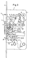
- Fig. 3 shows the door lock when the bolt 29 is retracted, but the latch 9 is pushed out, in which the electric motor 37 has brought the control part 43 closer to the latch 9 while the latch 29 is retracted.
- the slot 61 controlling the movement of the bolt 29 is essentially Z-shaped, with the ends of a central portion 65 of the slot which runs obliquely both to the direction of movement of the bolt 29 and to the direction of movement of the control part 43 61 Connect end sections 67, 69 running perpendicular to the direction of movement of the bolt 29.
- the end sections 67, 69 receive the pin 63 in the fully extended or fully inserted position of the latch 29 and thus secure the violent insertion or removal of the latch 29.
- a pin 71 is attached to the latch head 31 the fully extended position of the latch 29 engages in a slot 73 of the control part 43 which is open in the direction of movement.
- the pin 71 which can alternatively also be attached to the control part 43 and then moves into a slot in the bolt head 31, secures the bolt 29 against forced insertion.
- the control part 43 also controls the retraction movement of the catch 9.
- the catch 9 adjacent to the control part 43 carries a finger 75 which, when the bolt 29 is drawn in, moves into a recess in the catch tail 13 delimited by a shoulder 77.
- the rack toothing 59 extends over the rectilinear region required for the locking movement and parallel to the faceplate 5 and is bent in a region in which the pin 63 of the locking head 31 enters the end section 69 of the slot 61 towards the faceplate 5, so that the pinion 57 meshing with the rack teeth 59 controls the control part 43 around the pin 63 in the Figures swings clockwise.
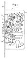
- the finger 75 takes, as shown in FIG. 4, the catch 9 in the feed direction.
- FIG. 4 shows the door lock with the bolt 29 drawn in by an electric motor and the latch 9 drawn in by an electric motor.
- the pins 33, 35 guiding the bolt tail 32 are arranged such that the control part 43 for the pivoting movement between the pins 33 , 63 can tilt.
- the corner adjacent to the faceplate is provided with a flat 79.
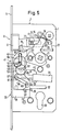
- the door lock can also be opened manually by pressing the lever handle, regardless of the electric motor drive, even if the bolt 29 is extended (panic function).
- 5 shows, by turning the handle arranged on the inside of the door, ie on the secured side of the door, the handle nut is pivoted, with which the finger 23 pulls the latch 9 over the shoulder 25 provided on the latch tail 13.
- a projection 81 formed on the follower 21 takes the control part 43 with it in the opening direction of the bolt 29.
- the projection 81 abuts a projection 83 of the control part 43, for example a bent tab of the control part 43.
- the forced movement of the control part 43 is transmitted via the inclined surfaces of the slot 61 and the pin 63 to the bolt 29, which is thereby shifted into its retracted position.
- the overload clutch 51 arranged in the drive path of the transmission 41 between the electric motor 37 and the control part 43 is overcome when the control part 43 is operated manually and uncouples the self-locking worm 45.
- the overload clutch 51 protects moreover, when the door lock is driven by an electric motor, the electric motor 37 and the gear 43 against overload.
- FIG. 6 and 7 show details of the overload clutch 51 used in the door lock of FIG. 1.
- the overload clutch is arranged in the drive path between the worm wheel 49 meshing with the worm 45 and the pinion 53 arranged coaxially with the worm wheel 49.
- the overload clutch 51 can also be provided at any other point on the transmission 41.
- the overload clutch 51 of FIGS. 6 and 7 is designed as a latching clutch and comprises a pawl 85 which is pivotably mounted on the worm wheel 49 by means of a pin 87 about a pivot axis parallel to the axis of rotation of the worm wheel 49.
- the pinion 53 which is seated on a common axis 89 relative to the worm wheel 49, carries a clutch disk 91 which is connected to the pinion 53 in a rotationally fixed manner by means of projections 93.
- the clutch disc 91 has on its outer circumference a locking recess 95 into which a complementarily shaped locking projection 97 of the pawl 85 engages.
- a ring segment spring 103 which is guided on mushroom head rivets 99, 101 of the worm wheel 49 on the one side and the pawl 85 on the other hand, tensions the pawl 85 radially against the clutch disc 91 Detent recess 95 of the clutch disc 91 is raised and the pinion 53 is uncoupled from the worm wheel 49.
- FIGS. 8 and 9 show variants of the overload clutch which can be used instead of the overload clutch 51 of the door lock of FIG. 1.
- FIGS. 1 to 7 show variants of the overload clutch which can be used instead of the overload clutch 51 of the door lock of FIG. 1.
- FIGS. 1 to 7 show variants of the overload clutch which can be used instead of the overload clutch 51 of the door lock of FIG. 1.
- FIGS. 1 to 7 show variants of the overload clutch which can be used instead of the overload clutch 51 of the door lock of FIG. 1.
- FIG. 8 shows a slip clutch 51a in the drive path of the transmission between the worm wheel 49a meshing with the worm 45a and the pinion 53a rotatable on a common axis 89a relative to the worm wheel 49a.
- a friction ring disk 107 made of an elastomer-elastic material sits in a recess 105 of the worm wheel 49a.
- a clutch disc 91a which is connected in a rotationally fixed manner to the pinion 53a by means of a positive fit, is in frictional contact with the friction ring disc 107.
- the axial friction pretension is generated by the elastic properties of the friction ring disk 107, the axial reaction forces being absorbed by the side wall plate 1a of the door lock and the bearing plate 47a of the transmission. It is understood that the axial preload can also be generated by separate springs.
- Fig. 9 shows an overload clutch 51b, in which one of the step gears is mounted so that it can move radially, so that when a predetermined torque is exceeded, it can come out of engagement with its counter-toothing.
- the worm wheel 49b which meshes with the worm 45b, is connected in a rotationally fixed manner to the pinion 53b seated on the common axis 89b.
- the axis 89b is mounted on both sides of the gears 49b, 53b in bushings 109, 111 made of an elastomer-elastic material.
- the bearing bushes 109, 111 are seated in the side wall plate 1b of the door lock or the bearing plate 47b of the transmission and absorb the radial evasive movement of the gear wheels 49b, 53b or their axis 89b in a springy manner when the drive path is overloaded. It is understood that the axis 89b is also guided radially deflectable in some other way and radially resilient can be biased. The axis 89b can in particular be guided radially in elongated holes in the plates 1b, 47b.
- Variants of the plug-in door lock driven by an electric motor are explained below, which differ from the door lock of FIG. 1 essentially only in the type of coupling of the control part to the latch. Components having the same effect are identified by reference numerals in FIG. 1 and, to distinguish them, by an additional letter.
- FIGS. 1 to 7 For a more detailed explanation of the structure and the mode of operation, reference is made to the description of FIGS. 1 to 7.
- the variants of the overload clutch explained with reference to FIGS. 8 and 9 can also be used in the variants of the door lock explained below.
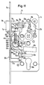
- the control part 43c of the door lock shown in FIGS. 10 and 11 is in turn guided displaceably between the faceplate 5c on the one hand and guide pins 33c, 35c of the bolt tail 32c at right angles to the direction of movement of the bolt 29c and coupled to the bolt 29c via the oblique push slot 61c and the guide pin 63c .
- the control part 43c is guided in a linearly displaceable manner and carries at its end adjacent to the case 9c a thrust finger 113 which is opposed by an oblique push surface 115 on the case 9c.
- FIG. 10 shows the door lock with the bolt 29c pushed out, in which the electric motor 37c has shifted the control part 43c via the gear 41c and the rack toothing 59c, which in this embodiment is entirely straight, into its position remote from the latch 9c.
- 11 shows the door lock with solid lines 29c with the electric motor retracted.
- the thrust finger 113 has approached the inclined thrust surface 115 of the latch 9c. If the control part 43c is driven further in the pulling direction of the bolt 29c, the thrust finger takes 113 the trap 9c in the retraction direction up to the retracted position shown in broken lines in FIG.
- the pin 63c engages in the end section 69c of the oblique push slot 61c which extends in the direction of displacement of the control part 43c.
- the oblique push surface 115 forms the boundary of a recess in the latch 9c, so that the latch can also be pulled in manually via the door handle, regardless of the electromotive adjustment of the latch 29c.
- the overload clutch 51c arranged in the drive path of the transmission 41c between the electric motor 37c and the control part 43c in turn protects the drive path against overload and enables the follower 21c or the control part 43c to unlock and open the door lock in emergency situations via the driving stops 81c, 83c.
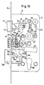
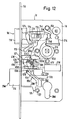
- the electric motor 37d drives the control part 41d in both directions of movement via the gear 41d and the rack toothing 59d provided on the control part 43d.
- an angle lever 117 is pivotally mounted on the lock housing 7d, which is carried with its first arm 119 by a stop surface 121 of the control part 43d adjacent to the latch 9d to the latch 9d and with its other arm 123 via the on the shoulder tail 13d provided shoulder 77d takes the trap 9d in the pulling direction.
- FIG. 12 shows the door lock with solid lines 29d and the latch 9d extended.
- the control part 43d is in its position remote from the latch 9d. If the control part 43d is approached by the electric motor 37d to the latch 9d, the bolt 29d is retracted, and in the case of the retracted position of the bolt 29d beyond the stroke of the control part 43d, the latch 9d is subsequently also pulled in via the angle lever 117.
- Fig. 12 shows with dashed lines the control part 43d and the angle lever 117 with the trap 9d retracted.
- the overload clutch 51d provided in the drive path of the transmission 41d in turn protects the drive path against overload and allows the locked door lock to be opened manually by actuating the handle.
- the follower nut 21d carries a driver stop 81d, which takes the control part 43d in the opening direction of the bolt 29d via a counter-stop, here in the form of a recess 83d into which the stop 81d engages.
- a projection 125 is formed on the side of the control part 43d remote from the catch, which can be supported on a pin 127 fixed to the housing when the bolt 29d is fully inserted.
- This type of additional slide-in protection can also be provided in the door locks explained above.
Abstract
Description
Die Erfindung betrifft ein elektromotorisch angetriebenes Türschloß gemäß dem Oberbegriff des Anspruchs 1.The invention relates to an electric motor-driven door lock according to the preamble of claim 1.
Aus der DE-A-36 06 620 ist ein elektromotorisch angetriebenes Türschloß bekannt, dessen Riegel von einem Elektromotor über ein Zahnradgetriebe in das Schloßgehäuse eingezogen und aus dem Schloßgehäuse ausgefahren werden kann. Das Ausgangszahnrad des Getriebes ist als Segmentzahnrad ausgebildet, welches mit einer fest mit dem Riegel verbundenen Zahnstangenverzahnung kämmt. In der eingezogenen Stellung des Riegels fährt das Segmentzahnrad aus der Zahnstangenverzahnung aus und zieht über einen Wechselhebel nachfolgend die Falle ein. Das bekannte Türschloß läßt sich damit einschließlich des Einziehens der Falle elektrisch, beispielsweise mittels eines elektronisch kodierten Schlüssels, steuern. Die in Ausschubrichtung federnd vorgespannte Falle läßt sich jedoch auch über einen Türdrücker manuell öffnen. Um auch den Riegel des Türschlosses in Notsituationen oder bei Ausfall der elektrischen Steuerung manuell öffnen zu können, ist ein zusätzliches mechanisches Zylinderschloß vorgesehen, durch das ein schwenkbar gelagertes Zahnrad des Getriebes vom Antriebsweg des Motors abgeschaltet und in Eingriff mit einer Antriebsverzahnung der Drückernuß gebracht werden kann.From DE-A-36 06 620 an electric motor-driven door lock is known, the bolt of which can be drawn into the lock housing by an electric motor via a gear transmission and can be extended from the lock housing. The output gear of the transmission is designed as a segment gear, which meshes with a rack toothing firmly connected to the bolt. In the retracted position of the bolt, the segment gear wheel extends from the rack teeth and then pulls in the latch via a change lever. The known door lock can thus be controlled electrically, for example by means of an electronically coded key, including the retraction of the latch. However, the latch, which is spring-biased in the extension direction, can also be opened manually using a door handle. In order to be able to manually open the bolt of the door lock in emergency situations or in the event of a failure of the electrical control, an additional mechanical cylinder lock is provided, by means of which a pivoted gear wheel of the gearbox can be switched off from the drive path of the motor and brought into engagement with a drive toothing of the follower nut .
Das Getriebe des bekannten Türschlosses ist vergleichsweise aufwendig, und für das manuelle Einziehen des Riegels ist ein zusätzliches Zylinderschloß erforderlich.The transmission of the known door lock is comparatively complex, and an additional cylinder lock is required for the manual retraction of the bolt.
Es ist Aufgabe der Erfindung, den konstruktiven Aufwand des bekannten Türschlosses zu verringern und insbesondere das den Elektromotor mit dem Riegel kuppelnde Getriebe zu vereinfachen, wobei sichergestellt sein soll, daß der Riegel zum Beispiel in Notsituationen auch manuell eingezogen werden kann, ohne daß das Getriebe manuell umgeschaltet werden muß oder die mechanischen Komponenten des elektromotorischen Antriebs beeinträchtigt werden.It is an object of the invention to reduce the design effort of the known door lock and in particular to simplify the gear coupling the electric motor with the bolt, it being ensured that the bolt can also be pulled in manually, for example in emergency situations, without the gear being manually must be switched or the mechanical components of the electromotive Drive can be affected.
Diese Aufgabe wird erfindungsgemäß durch die im Kennzeichen des Anspruchs 1 angegebenen Merkmale gelöst.This object is achieved by the features specified in the characterizing part of claim 1.
Im Rahmen der Erfindung ist die zur Umsetzung der Rotationsbewegung des Elektromotors in eine Translationsbewegung vorgesehene Zahnstangenverzahnung nicht unmittelbar an dem Riegel vorgesehen, sondern an einem quer zur Riegelbewegung translatorisch verschiebbar geführten Steuerteil. Das Steuerteil ist für beide Bewegungsrichtungen des Riegels über Schrägschubflächen mit dem Riegel gekuppelt. Das Steuerteil kann über die der eingezogenen Endstellung des Riegels zugeordnete Position hinaus bewegt werden und nimmt über einen Mitnehmeranschlag die Falle in Einzugsrichtung mit. Die Falle ist im übrigen unabhängig von der Betätigung durch das Steuerteil herkömmlich über eine Drückernuß auch manuell einziehbar. Für die manuelle Einziehbewegung muß die vom Motor zum Riegel führende Getriebekette nicht aufgetrennt werden.In the context of the invention, the toothed rack toothing provided for converting the rotational movement of the electric motor into a translational movement is not provided directly on the bolt, but rather on a control part which is displaceably guided transversely to the bolt movement. The control part is coupled to the bolt for both directions of movement of the bolt via inclined push surfaces. The control part can be moved beyond the position assigned to the retracted end position of the bolt and takes the catch in the pulling direction via a driver stop. The trap is also conventionally manually retracted independently of the actuation by the control part via a follower. The gear chain leading from the motor to the bolt does not have to be broken for the manual retraction movement.
Die Maßnahmen des Anspruchs 2 erlauben es, in Notsituationen über den nur auf der Türinnenseite vorgesehenen Türdrücker nicht nur die Falle zu öffnen, sondern auch mechanisch den Riegel einzuziehen. Es müssen keine Zahnräder des Getriebes manuell auf eine andere Getriebekette umgeschaltet werden. Die Überlastkupplung schützt darüberhinaus Motor und Getriebe vor Überlastungsschäden. Die Überlastkupplung kann als Rutschkupplung oder Rastkupplung, insbesondere als Rastklinkenkupplung, ausgebildet sein. Gegebenenfalls kann die Überlastkupplung auch durch ein radial beweglich gelagertes und federnd in Eingriff mit seiner Gegenverzahnung vorgespanntes Zwischenzahnrad gebildet sein.The measures of claim 2 allow, in emergency situations, not only to open the latch, but also to pull in the bolt mechanically via the lever handle provided only on the inside of the door. No gearwheels of the transmission have to be switched manually to another transmission chain. The overload clutch also protects the engine and gearbox from damage caused by overloading. The overload clutch can be designed as a slip clutch or snap-in clutch, in particular as a snap-in clutch. If necessary, the overload clutch can also be formed by an intermediate gearwheel which is mounted so as to be radially movable and resiliently biased into engagement with its counter-toothing.
Das Steuerteil ist für die Einzugsbewegung des Riegels zweckmäßigerweise quer zur Bewegungsrichtung der Falle auf diese zu verschiebbar und wirkt erst bei seiner über die eingezogene Stellung des Riegels hinausführenden Bewegung über einen Mitnehmeranschlag oder dergleichen in Einzugsrichtung auf die Falle ein. Der translatorische Antrieb der Falle in Einzugsrichtung läßt sich hierbei, ausgehend von dem elektromotorisch angetriebenen Steuerteil in unterschiedlichster Weise realisieren. In der Ausgestaltung nach Anspruch 8 wird das Steuerteil lediglich während des den Riegel schiebenden Hubs translatorisch verschiebbar geführt. In der eingezogenen Stellung gibt die Führung das Steuerteil für eine Schwenkbewegung seines der Falle benachbarten Endes in Einzugsrichtung der Falle frei, so daß das von dem Elektromotor angetriebene Steuerteil eine Schwenkbewegung ausführen und die Falle unmittelbar in Einzugsrichtung antreiben kann. In einer zweiten Variante nach Anspruch 9 nimmt das translatorisch verschiebbar geführte Steuerteil die Falle über ein Schrägflächengetriebe in Einzugsrichtung mit. Ein ähnlicher Effekt wird nach Anspruch 10 mit einem Winkelhebel erreicht, der die Schubkraft des quer zur Falle bewegbaren Steuerteils in eine in Einzugsrichtung der Falle wirkende Schubkraft umlenkt.The control part is for the retraction of the bolt Expediently displaceable transversely to the direction of movement of the latch and only acts on the latch in the direction of retraction when it moves beyond the retracted position of the bolt via a driver stop or the like. The translational drive of the trap in the pull-in direction can be implemented in a wide variety of ways, starting from the electromotive-driven control part. In the embodiment according to claim 8, the control part is guided to be translationally displaceable only during the stroke pushing the bolt. In the retracted position, the guide releases the control part for a pivoting movement of its end adjacent to the trap in the pulling-in direction of the trap, so that the control part driven by the electric motor can carry out a pivoting movement and drive the trap directly in the pulling-in direction. In a second variant according to claim 9, the control part, which is guided in a translationally displaceable manner, takes the catch with it via an inclined surface gear in the feed direction. A similar effect is achieved according to
Das Steuerteil wird zweckmäßigerweise an Seitenwänden des Schloßgehäuses verschiebbar geführt. Bei Einsteck-Türschlössern wird gemäß Anspruch 13 vorzugsweise die Stulpschiene, die eine Schmalseitenwand des Schloßgehäuses bildet, ausgenutzt. Auf diese Weise läßt sich mit verhältnismäßig geringem Konstruktionsaufwand eine stabile und exakte Führung erreichen.The control part is expediently guided on the side walls of the lock housing. In the case of mortise door locks, the faceplate, which forms a narrow side wall of the lock housing, is preferably used. In this way, stable and exact guidance can be achieved with relatively little design effort.
Das Steuerteil wird zweckmäßigerweise zur Sicherung des Riegels gegen gewaltsames Einschieben oder Herausziehen mit ausgenutzt. Nach Anspruch 14 wird dies durch rechtwinklig zur Bewegungsrichtung des Riegels verlaufende Endabschnitte des das Steuerteil mit dem Riegel kuppelnden Kurvengetriebe-Schlitzes erreicht. Nach Anspruch 15 kann jedoch alternativ oder auch zusätzlich an dem Steuerteil oder dem Riegel ein in Bewegungsrichtung des Steuerteils verlaufender, endseitig offener Schlitz vorgesehen sein, in den in der eingezogenen Endstellung des Riegels ein Riegelvorsprung an dem jeweils anderen Teil eingreift.The control part is expediently used to secure the bolt against forced insertion or removal. According to claim 14, this is done by perpendicular to the direction of movement of the bolt end portions of the control part coupling with the bolt Cam gear slot reached. According to
Im folgenden werden Ausführungsbeispiele der Erfindung anhand einer Zeichnung näher erläutert. Hierbei zeigt:
- Fig. 1
- eine Seitenansicht eines elektromotorisch angetriebenen Einsteck-Türschlosses bei ausgeschobenem Riegel und ausgeschobener Falle, wobei der Übersichtlichkeit wegen eine Seitenwand abgenommen ist;
- Fig. 2
- eine teilweise Schnittansicht durch das Türschloß, gesehen entlang einer Linie II-II in Fig. 1;
- Fig. 3
- eine Seitenansicht des Türschlosses nach Fig. 1 bei eingezogenem Riegel und ausgeschobener Falle;
- Fig. 4
- eine Seitenansicht des Türschlosses nach Fig. 1 bei eingezogenem Riegel und motorisch zurückgezogener Falle;
- Fig. 5
- eine Seitenansicht des Türschlosses nach Fig. 1 bei manueller Öffnung;
- Fig. 6
- eine Seitenansicht einer in dem Türschloß nach Fig. 1 einsetzbaren Überlastkupplung;
- Fig. 7
- eine Schnittansicht durch die Überlastkupplung, gesehen entlang einer Linie VII-VII in Fig. 6;
- Fig. 8 und 9
- Varianten der Überlastkupplung;
- Fig. 10
- eine Seitenansicht einer Variante eines elektromotorisch gesteuerten Einsteck-Türschlosses, ähnlich dem Türschloß der Fig. 1 bei ausgeschobenem Riegel und ausgeschobener Falle;
- Fig. 11
- eine Seitenansicht des Türschlosses nach Fig. 10 bei elektromotorisch eingezogenem Riegel und ausgeschobener Falle und
- Fig. 12
- eine Seitenansicht einer weiteren Variante eines Einsteck-Türschlosses ähnlich dem Türschloß der Fig. 1, bei ausgeschobenem Riegel und ausgeschobener Falle.
- Fig. 1
- a side view of an electric motor-driven mortise door lock when the bolt is pushed out and the latch is pushed out, a side wall being removed for the sake of clarity;
- Fig. 2
- a partial sectional view through the door lock, seen along a line II-II in Fig. 1;
- Fig. 3
- a side view of the door lock of Figure 1 with the bolt and retracted latch.
- Fig. 4
- a side view of the door lock of Figure 1 with the bolt drawn and the motor retracted latch.
- Fig. 5
- a side view of the door lock of Figure 1 with manual opening.
- Fig. 6
- a side view of an overload clutch which can be used in the door lock according to FIG. 1;
- Fig. 7
- a sectional view through the overload clutch, seen along a line VII-VII in Fig. 6;
- 8 and 9
- Variants of the overload clutch;
- Fig. 10
- a side view of a variant of an electromotively controlled mortise door lock, similar to the door lock of Figure 1 with the bolt and the latch extended;
- Fig. 11
- a side view of the door lock of FIG. 10 with the bolt drawn by an electric motor and the latch extended and
- Fig. 12
- a side view of another variant of a mortise door lock similar to the door lock of FIG. 1, with the bolt pushed out and the latch pushed out.
Die Fig. 1 und 2 zeigen ein Einsteck-Türschloß mit einem durch Seitenwandplatten 1, 3 und eine schmalseitig angeordnete Stulpschiene 5 begrenzten Schloßgehäuse 7. In dem Schloßgehäuse 7 ist eine Falle 9 rechtwinklig zur Stulpschiene 5 verschiebbar geführt, deren Kopf 11 durch eine nicht näher dargestellte Öffnung der Stulpschiene 5 austritt und deren Schwanz 13 an einem gehäusefesten, in ein Langloch 15 des Schwanzes 13 eingreifenden Zapfen 17 geführt ist. Eine am Schloßgehäuse 7 abgestützte Schenkelfeder 19 spannt die Falle 9 in Ausschubrichtung vor. Die Falle 9 kann mittels einer schwenkbar im Schloßgehäuse 7 gelagerten Drückernuß 21 mittels eines nicht näher dargestellten, auf der Türinnenseite angeordneten Drückers gegen die Schenkelfeder 19 eingezogen werden. Die Drückernuß 21 hat hierzu einen Finger 23, der über eine Schulter 25 des Fallenschwanzes 13 die Falle 9 in Einzugsrichtung mitnimmt. Eine Rückstellfeder 27 hält die Drückernuß 21 in einer die Falle 9 freigebenden Ruhestellung.1 and 2 show a mortise door lock with a lock housing 7 delimited by side wall panels 1, 3 and a
In dem Schloßgehäuse 7 ist im Abstand zur Falle 9 ein Riegel 29 rechtwinklig zur Stulpschiene 5 verschiebbar geführt, der mit seinem Riegelkopf 31 durch eine nicht näher dargestellte Öffnung der Stulpschiene 5 hindurchtritt und mit seinem Riegelschwanz 32 innerhalb des Schloßgehäuses 7 zwischen zwei gehäusefesten Zapfen 33, 35 geführt ist. Der Riegel 29 wird von einem Elektromotor 37 eingezogen und ausgeschoben, der auch unabhängig von der Drückerbetätigung die Falle 9 einzieht. Der Elektromotor 37 wird von einer nicht näher dargestellten Steuerschaltung, wie sie beispielsweise in der DE-A-36 06 620 beschrieben ist, gesteuert. Die Steuerung kann hierbei auf einen elektronisch kodierten Schlüssel ansprechen und eine in einem Schließzylinderkanal 39 des Türschlosses angeordnete Leseeinrichtung für den Schlüssel umfassen.In the lock housing 7, a
Der Elektromotor 37 treibt über ein Zahnradgetriebe 41 ein plattenförmiges Steuerteil 43 an, welches zwischen der Innenseite der Stulpschiene 5 und den Zapfen 33, 35 rechtwinklig zur Bewegungsrichtung sowohl der Falle 9 als auch des Riegels 29 linear verschiebbar geführt ist. Das zwischen der Falle 9 und dem Riegel 29 angeordnete Getriebe 41 umfaßt eine auf der Abtriebswelle des Elektromotors 37 sitzende Schnecke 45, die mit einem in der Seitenwandplatte 1 einerseits und einer gehäusefesten Lagerplatte 47 andererseits gelagerten Schneckenrad 49 kämmt. Das Schnekkenrad 49 ist über eine nachfolgend noch näher erläuterte, lediglich ein vorbestimmtes Drehmoment übertragende Überlastkupplung 51 mit einem gleichachsig angeordneten Ritzel 53 gekuppelt, welches seinerseits mit einem Zahnrad 55 kämmt. Das Zahnrad 55 treibt über ein Ritzel 57, welches in eine parallel zur Stulpschiene 5, d.h. parallel zur Verschieberichtung des Steuerteils 43 verlaufende Zahnstangenverzahnung 59 eingreift, das Steuerteil 43 an. Die rechtwinklig zur Bewegungsrichtung des Riegels 29 verlaufende Verschiebebewegung des Steuerteils 43 wird über einen schräg zu beiden Bewegungsrichtungen verlaufenden Schlitz 61 in dem Steuerteil, in welchen ein am Riegel 29 angebrachter Zapfen 63 eingreift, auf den Riegel 29 übertragen.The
Fig. 1 zeigt das Türschloß in gesperrtem Zustand, d.h. bei vollständig aus dem Schloßgehäuse 7 ausgeschobenem Riegel 29, in der das Steuerteil 43 in seine der Falle 9 entfernt gelegene Position gestellt ist. Fig. 3 zeigt das Türschloß bei eingezogenem Riegel 29, jedoch ausgeschobener Falle 9, in der der Elektromotor 37 das Steuerteil 43 der Falle 9 unter Einziehen des Riegels 29 angenähert hat. Wie die Fig. 1 und 3 zeigen, hat der die Bewegung des Riegels 29 steuernde Schlitz 61 im wesentlichen Z-Form, wobei sich an die Enden eines schräg sowohl zur Bewegungsrichtung des Riegels 29 als auch der Bewegungsrichtung des Steuerteils 43 verlaufenden Mittelabschnitts 65 des Schlitzes 61 senkrecht zur Bewegungsrichtung des Riegels 29 verlaufende Endabschnitte 67, 69 anschließen. Die Endabschnitte 67, 69 nehmen in der vollständig ausgeschobenen bzw. der vollständig eingeschobenen Stellung des Riegels 29 den Zapfen 63 auf und sichern so gewaltsames Einschieben bzw. Herausziehen des Riegels 29. Als zusätzliche Sicherung ist an dem Riegelkopf 31 ein Zapfen 71 angebracht, der in der vollständig ausgeschobenen Stellung des Riegels 29 in einen in Bewegungsrichtung offenen Schlitz 73 des Steuerteils 43 eingreift. Der Zapfen 71, der alternativ auch an dem Steuerteil 43 angebracht sein kann und dann in einen Schlitz des Riegelkopfs 31 einfährt, sichert den Riegel 29 gegen gewaltsames Einschieben.Fig. 1 shows the door lock in the locked state, i.e. with
Das Steuerteil 43 steuert auch die Einzugsbewegung der Falle 9. Der Falle 9 benachbart trägt das Steuerteil 43 einen Finger 75, der bei eingezogenem Riegel 29 in eine durch eine Schulter 77 begrenzte Aussparung des Fallenschwanzes 13 einfährt. Die Zahnstangenverzahnung 59 erstreckt sich über den für die Riegelbewegung erforderlichen, zur Stulpschiene 5 parallelen, geradlinigen Bereich hinaus und ist in einem Bereich, in welchem der Zapfen 63 des Riegelkopfs 31 in den Endabschnitt 69 des Schlitzes 61 eintritt, zur Stulpschiene 5 hin gebogen, so daß das mit der Zahnstangenverzahnung 59 kämmende Ritzel 57 das Steuerteil 43 um den Zapfen 63 herum in den Figuren im Uhrzeigersinn schwenkt. Der Finger 75 nimmt hierbei, wie Fig. 4 zeigt, die Falle 9 in Einzugsrichtung mit. Fig. 4 zeigt das Türschloß bei elektromotorisch eingezogenem Riegel 29 und elektromotorisch eingezogener Falle 9. Um die Schwenkbewegung des Steuerteils 43 zu ermöglichen, sind die den Riegelschwanz 32 führenden Zapfen 33, 35 so angeordnet, daß das Steuerteil 43 für die Schwenkbewegung zwischen den Zapfen 33, 63 kippen kann. Die der Stulpschiene benachbarte Ecke ist mit einer Abflachung 79 versehen.The
Das Türschloß läßt sich unabhängig von dem elektromotorischen Antrieb notfalls auch manuell durch Betätigen des Türdrückers öffnen und zwar auch dann, wenn der Riegel 29 ausgeschoben ist (Panikfunktion). Wie Fig. 5 zeigt, wird durch Drehen des auf der Türinnenseite, d.h. auf der gesicherten Seite der Türe angeordneten Drückers, die Drükkernuß geschwenkt, womit der Finger 23 über die am Fallenschwanz 13 vorgesehene Schulter 25 die Falle 9 einzieht. Zugleich nimmt ein an der Drückernuß 21 angeformter Vorsprung 81 das Steuerteil 43 in Öffnungsrichtung des Riegels 29 mit. Der Vorsprung 81 schlägt hierbei an einem Vorsprung 83 des Steuerteils 43, beispielsweise einem angebogenen Lappen des Steuerteils 43, an. Die Zwangsbewegung des Steuerteils 43 wird über die Schrägflächen des Schlitzes 61 und den Zapfen 63 auf den Riegel 29 übertragen, der hierdurch in seine eingezogene Stellung verschoben wird. Die im Antriebsweg des Getriebes 41 zwischen dem Elektromotor 37 und dem Steuerteil 43 angeordnete Überlastkupplung 51 wird bei der manuellen Betätigung des Steuerteils 43 überwunden und kuppelt die an sich selbsthemmende Schnecke 45 ab. Die Überlastkupplung 51 schützt darüberhinaus bei elektromotorischem Antrieb des Türschlosses den Elektromotor 37 und das Getriebe 43 vor Überlastung.The door lock can also be opened manually by pressing the lever handle, regardless of the electric motor drive, even if the
Die Fig. 6 und 7 zeigen Einzelheiten der im Türschloß der Fig. 1 verwendeten Überlastkupplung 51. Im dargestellten Ausführungsbeispiel ist die Überlastkupplung im Antriebsweg zwischen dem mit der Schnecke 45 kämmenden Schneckenrad 49 und dem gleichachsig zum Schneckenrad 49 angeordneten Ritzel 53 angeordnet. Die Überlastkupplung 51 kann jedoch auch an jeder anderen Stelle des Getriebes 41 vorgesehen sein.6 and 7 show details of the overload clutch 51 used in the door lock of FIG. 1. In the exemplary embodiment shown, the overload clutch is arranged in the drive path between the
Die Überlastkupplung 51 der Fig. 6 und 7 ist als Rastkupplung ausgebildet und umfaßt eine Klinke 85, die um eine zur Drehachse des Schneckenrads 49 parallele Schwenkachse schwenkbar mittels eines Zapfens 87 an dem Schneckenrad 49 gelagert ist. Das relativ zu dem Schneckenrad 49 auf einer gemeinsamen Achse 89 sitzende Ritzel 53 trägt eine Kupplungsscheibe 91, die mit dem Ritzel 53 über Vorsprünge 93 durch Formschluß drehfest verbunden ist. Die Kupplungsscheibe 91 hat an ihrem Außenumfang eine Rastaussparung 95, in die ein komplementär geformter Rastvorsprung 97 der Klinke 85 eingreift. Eine an Pilzkopfnieten 99, 101 des Schneckenrads 49 einerseites und der Klinke 85 andererseits geführte Ringsegmentfeder 103 spannt die Klinke 85 radial gegen die Kupplungsscheibe 91. Bei Überschreiten eines durch die Federkraft und die Form der Rastorgane bestimmten Drehmoments wird der Rastvorsprung 97 der Klinke 85 aus der Rastaussparung 95 der Kupplungsscheibe 91 gehoben und das Ritzel 53 von dem Schneckenrad 49 abgekuppelt.The overload clutch 51 of FIGS. 6 and 7 is designed as a latching clutch and comprises a
Die Fig. 8 und 9 zeigen Varianten der Überlastkupplung, die anstelle der Überlastkupplung 51 des Türschlosses der Fig. 1 verwendbar sind. In der folgenden Beschreibung sind gleichwirkende Komponenten mit den Bezugszahlen der Fig. 1 bis 7 bezeichnet und zur Unterscheidung mit einem Buchstaben versehen. Zur näheren Erläuterung wird auf die Beschreibung der Fig. 1 bis 7 Bezug genommen.8 and 9 show variants of the overload clutch which can be used instead of the
Fig. 8 zeigt eine Rutschkupplung 51a im Antriebsweg des Getriebes zwischen dem mit der Schnecke 45a kämmenden Schneckenrad 49a und dem auf einer gemeinsamen Achse 89a relativ zu dem Schneckenrad 49a drehbaren Ritzel 53a. In einer Aussparung 105 des Schneckenrads 49a sitzt eine Reibringscheibe 107 aus einem elastomer-elastischen Material. Eine über Zapfen 93a durch Formschluß drehfest mit dem Ritzel 53a verbundene Kupplungsscheibe 91a liegt flächig reibend an der Reibringscheibe 107 an. Die axiale Reibvorspannung wird durch die elastischen Eigenschaften der Reibringscheibe 107 erzeugt, wobei die axialen Reaktionskräfte von der Seitenwandplatte 1a des Türschlosses und der Lagerplatte 47a des Getriebes aufgenommen werden. Es versteht sich, daß die axiale Vorspannung auch durch gesonderte Federn erzeugt werden kann.8 shows a slip clutch 51a in the drive path of the transmission between the
Fig. 9 zeigt eine Überlastkupplung 51b, bei welcher eines der Stufenzahnräder radial beweglich gelagert ist, so daß es bei Überschreiten eines vorbestimmten Drehmoments außer Eingriff mit seiner Gegenverzahnung kommen kann. Bei der Überlastkupplung 51b ist das mit der Schnecke 45b kämmende Schneckenrad 49b drehfest mit dem auf der gemeinsamen Achse 89b sitzenden Ritzel 53b verbunden. Die Achse 89b ist beiderseits der Zahnräder 49b, 53b in Lagerbuchssen 109, 111 aus einem elastomer-elastischen Material gelagert. Die Lagerbuchsen 109, 111 sitzen in der Seitenwandplatte 1b des Türschlosses bzw. der Lagerplatte 47b des Getriebes und nehmen bei Überlastung des Antriebswegs radial federnd die radiale Ausweichbewegung der Zahnräder 49b, 53b bzw. deren Achse 89b auf. Es versteht sich, daß die Achse 89b auch anderweitig radial auslenkbar geführt und radial federnd vorgespannt sein kann. Die Achse 89b kann insbesondere in Langlöchern der Platten 1b, 47b radial geführt sein.Fig. 9 shows an overload clutch 51b, in which one of the step gears is mounted so that it can move radially, so that when a predetermined torque is exceeded, it can come out of engagement with its counter-toothing. In the overload clutch 51b, the
Im folgenden werden Varianten des elektromotorisch angetriebenen Einsteck-Türschlosses erläutert, die sich von dem Türschloß der Fig. 1 im wesentlichen nur durch die Art der Kopplung des Steuerteils mit der Falle unterscheiden. Gleichwirkende Komponenten sind mit Bezugszahlen der Fig. 1 und zur Unterscheidung mit einem zusätzlichen Buchstaben bezeichnet. Zur näheren Erläuterung des Aufbaus und der Wirkungsweise wird auf die Beschreibung der Fig. 1 bis 7 Bezug genommen. Auch bei den nachfolgend erläuterten Varianten des Türschlosses sind die anhand der Fig. 8 und 9 erläuterten Varianten der Überlastkupplung verwendbar.Variants of the plug-in door lock driven by an electric motor are explained below, which differ from the door lock of FIG. 1 essentially only in the type of coupling of the control part to the latch. Components having the same effect are identified by reference numerals in FIG. 1 and, to distinguish them, by an additional letter. For a more detailed explanation of the structure and the mode of operation, reference is made to the description of FIGS. 1 to 7. The variants of the overload clutch explained with reference to FIGS. 8 and 9 can also be used in the variants of the door lock explained below.
Das Steuerteil 43c des in den Fig. 10 und 11 dargestellten Türschlosses ist wiederum zwischen der Stulpschiene 5c einerseits und Führungszapfen 33c, 35c des Riegelschwanzes 32c rechtwinklig zur Bewegungsrichtung des Riegels 29c verschiebbar geführt und über den Schrägschubschlitz 61c sowie den Führungszapfen 63c mit dem Riegel 29c gekuppelt. Das Steuerteil 43c ist ausschließlich linear verschiebbar geführt und trägt an seinem der Falle 9c benachbarten Ende einen Schubfinger 113, dem an der Falle 9c eine Schrägschubfläche 115 gegenüberliegt. Fig. 10 zeigt das Türschloß bei ausgeschobenem Riegel 29c, bei welcher der Elektromotor 37c das Steuerteil 43c über das Getriebe 41c und die in dieser Ausführungsform insgesamt geradlinige Zahnstangenverzahnung 59c in seine der Falle 9c entfernt gelegene Stellung verschoben hat. Fig. 11 zeigt mit ausgezogenen Linien das Türschloß bei elektromotorisch eingezogenem Riegel 29c. In dieser Stellung hat sich der Schubfinger 113 der Schrägschubfläche 115 der Falle 9c angenähert. Wird das Steuerteil 43c in Einzugsrichtung des Riegels 29c weiter angetrieben, so nimmt der Schubfinger 113 die Falle 9c in Einzugsrichtung bis in die in Fig. 11 gestrichelt eingezeichnete, eingezogene Stellung mit. Im Falleneinzugshub des Steuerteils 43c greift der Zapfen 63c in den in Verschieberichtung des Steuerteils 43c verlaufenden Endabschnitt 69c des Schrägschubschlitzes 61c ein. Die Schrägschubfläche 115 bildet die Begrenzung einer Aussparung der Falle 9c, so daß die Falle unabhängig von der elektromotorischen Verstellung des Riegels 29c auch manuell über den Türdrücker eingezogen werden kann. Die im Antriebsweg des Getriebes 41c zwischen dem Elektromotor 37c und dem Steuerteil 43c angeordnete Überlastkupplung 51c schützt wiederum den Antriebsweg vor Überlastung und ermöglicht über die Mitnahmeanschläge 81c, 83c der Drückernuß 21c bzw. des Steuerteils 43c das Entriegeln und Öffnen des Türschlosses in Notsituationen.The
Das elektromotorisch antreibbare Einstecktürschloß der Fig. 12 hat wiederum ein längs der Stulpschiene 5d geführtes Steuerteil 43d, das über einen Schrägschubschlitz 61d für beide Bewegungsrichtungen mit dem Riegel 29d gekuppelt ist. Der Elektromotor 37d treibt das Steuerteil 41d in beiden Bewegungsrichtungen über das Getriebe 41d und die an dem Steuerteil 43d vorgesehene Zahnstangenverzahnung 59d an. Für den Antrieb der Falle 9d in Einzugsrichtung ist an dem Schloßgehäuse 7d ein Winkelhebel 117 schwenkbar gelagert, der mit seinem ersten Arm 119 von einer der Falle 9d benachbarten Anschlagfläche 121 des Steuerteils 43d zur Falle 9d hin mitgenommen wird und mit seinem anderen Arm 123 über die am Fallenschwanz 13d vorgesehene Schulter 77d die Falle 9d in Einzugsrichtung mitnimmt. Fig. 12 zeigt mit ausgezogenen Linien das Türschloß bei ausgeschobenem Riegel 29d und ausgeschobener Falle 9d. Das Steuerteil 43d befindet sich hierbei in seiner der Falle 9d entfernt gelegenen Stellung. Wird das Steuerteil 43d von dem Elektromotor 37d der Falle 9d angenähert, so wird der Riegel 29d eingezogen, und bei dem über die eingezogene Stellung des Riegels 29d hinausgehenden Hub des Steuerteils 43d wird über den Winkelhebel 117 nachfolgend auch die Falle 9d eingezogen. Fig. 12 zeigt mit gestrichelten Linien das Steuerteil 43d und den Winkelhebel 117 bei eingezogener Falle 9d.The plug-in door lock of FIG. 12, which can be driven by an electric motor, in turn has a
Die im Antriebsweg des Getriebes 41d vorgesehene Überlastkupplung 51d schützt wiederum einerseits den Antriebsweg vor Überlastung und erlaubt das manuelle Öffnen des verriegelten Türschlosses durch Betätigen des Drückers. Die Drückernuß 21d trägt einen Mitnehmeranschlag 81d, der über einen Gegenanschlag, hier in Form einer Aussparung 83d, in die der Anschlag 81d eingreift, das Steuerteil 43d in Öffnungsrichtung des Riegels 29d mitnimmt.The overload clutch 51d provided in the drive path of the
Für die zusätzliche Sicherung des Riegels 29d gegen gewaltsames Einschieben ist auf der fallenfernen Seite des Steuerteils 43d ein Vorsprung 125 angeformt, der sich bei vollständig eingeschobenem Riegel 29d an einem gehäusefesten Zapfen 127 abstützen kann. Diese Art der zusätzlichen Einschubsicherung kann auch bei den vorstehend erläuterten Türschlössern vorgesehen werden.For the additional securing of the
Claims (15)
- An electromotively driven door lock, comprising a lock housing (7), a latch (9) which can be retracted into the lock housing (7) against a push-out spring (19) via a handle, a bolt (29) displaceable between a retracted position and an extended position and an actuator (37, 41, 43) with an electric motor (37), with a gearing (41, 43) coupling the electric motor (37) to the bolt (29) for both directions of movement and with a driving device (75, 77; 113, 115; 117) for the latch (9), which, upon actuation of the gearing (41, 43) in the direction of retraction of the bolt (29), drives the latch (9) in the retraction direction beyond the retracted position of the bolt (29), characterized in that the actuator (37, 41, 43) comprises a control portion (43) guided displaceably on the lock housing (7) perpendicularly to the direction of movement of the bolt (29), which control portion (43) is coupled with the bolt (29) via a cam mechanism (61, 63) with thrust surfaces running at an angle to the directions of movement of the bolt (29) and of the control portion (43) and which, upon its movement associated with the direction of retraction of the bolt (29) and driving the latch (9), can be moved beyond the position associated with the retracted bolt (29).
- A door lock according to claim 1, characterized in that an overload coupling limiting the transmissible torque is arranged in the drive path of the gearing (41, 43) between the electric motor (37) and the control portion (43) and in that a push nut (21) operable by means of the handle carries a drive stop (81) which, by means of a counter stop (83) on the control portion (43), drives the control portion (43) upon the latch retraction movement of the push nut (21) in the bolt retraction direction.
- A door lock according to claim 2, characterized in that the overload coupling is constructed as a sliding coupling (51a).
- A door lock according to claim 2, characterized in that the overload coupling (51) is constructed as a detent coupling.
- A door lock according to claim 4, characterized in that the detent coupling (51) couples together two coaxially arranged toothed wheels (49, 53) of a stepped gear and comprises a stop catch (85) which is accommodated radially swivellably on the toothed wheel (49) of larger diameter and which engages resiliently in a radial recess (95) in the toothed wheel (53) of smaller diameter.
- A door lock according to claim 2, characterized in that, to form the overload coupling (51b), the gearing (41, 43) comprises an intermediate toothed wheel (49b) accommodated radially movably and in resiliently biased engagement with its countertoothing.
- A door lock according to any one of claims 1 to 6, characterized in that the gearing (41, 43) is constructed as a toothed wheel gearing, whose output pinion (57) meshes with a toothed rack (59) extending on the control portion (43) in the direction of displacement thereof.
- A door lock according to claim 7, characterized in that the control portion (43) for the retraction movement of the bolt (29) is displaceable towards the latch (9) perpendicularly to the direction of movement thereof and comprises a drive stop (75) adjacent the latch (9) and which may be brought into engagement with the latch (9) when the bolt (29) is in the retracted position, in that the control portion (43) is guided displaceably in a guide (5, 33, 35), which permits a swivel movement of the control portion (43) in the retraction direction of the latch (9) when the bolt (29) is in the retracted position and in that the area of the toothed rack (59) driving the control portion (43) beyond the position associated with the retracted bolt (29) runs perpendicularly to the area of the toothed rack (59) driving the bolt (29).
- A door lock according to any one of claims 1 to 7, characterized in that the control portion (43c) for the retraction movement of the bolt (29c) is displaceable towards the latch (9c) perpendicularly to the direction of movement thereof and, upon its displacement in the retraction direction of the bolt (29) beyond the position associated with the retracted bolt (29c), drives the latch (9c) over a thrust surface (115) of a cam mechanism (113, 115) driving the latch (9c) in the retraction direction, said thrust surface (115) running at an angle to the directions of displacement of both the control portion (43c) and the latch (9c).
- A door lock according to any one of claims 1 to 7, characterized in that the control portion (43d) for the retraction movement of the bolt (29d) is displaceable towards the latch (9d) perpendicularly to the direction of movement thereof and comprises a drive stop (121) adjacent the latch (9d), which drive stop (121), upon its displacement in the retraction direction of the bolt (29d) leading beyond the position associated with the retracted bolt (29d), drives the latch (9d) in the retraction direction by means of an angular lever (117) accommodated swivellably on the lock housing (7d).
- A door lock according to any one of claims 1 to 10, it being constructed as a mortise lock whose bolt (29) and latch (9) are displaceable at right angles to a lock plate (5) forming a narrow side wall of the lock housing (7), characterized in that the control portion (43) is guided displaceably on the inside of the lock plate (5).
- A door lock according to claim 11, characterized in that the gearing (41, 43), including the toothed rack (59), is arranged in the region of the lock housing (7) between the bolt (29) and the latch (9).
- A door lock according to any one of claims 1 to 12, characterized in that the cam mechanism (61, 63) coupling the bolt (29) with the control portion (43) comprises a slit (61) in the control portion (43), the slit (61) cunning at an angle to the directions of movement of the bolt (29) and of the control portion (43), and a pin (63) which is on the bolt (29) and which engages in the slit (61).
- A door lock according to claim 13, characterized in that the slit (61) has a Z-shape, end sections (67, 69) running substantially at right angles to the direction of movement of the bolt (29) adjoining a central section (65) of the slit (61) running at an angle to the directions of movement of the bolt (29) and ofthe control portion (43).
- A door lock according to any one of claims 1 to 14, characterized in that the bolt (29) and the control portion (43) are provided with locking members (71, 73) associated with each other and securing the extended bolt (29) against being pushed back into the lock housing (7), one of which locking members (71, 73) is constructed as a slit (73) open at the end and running substantially in the direction of movement of the control portion (43) and the other is constructed as a bolt projection (71) which can be introduced into the slit (73) when the bolt (29) is in the retracted position.
Priority Applications (1)
| Application Number | Priority Date | Filing Date | Title |
|---|---|---|---|
| AT88120642T ATE76473T1 (en) | 1987-12-11 | 1988-12-09 | ELECTRIC MOTOR DRIVEN DOOR LOCK. |
Applications Claiming Priority (2)
| Application Number | Priority Date | Filing Date | Title |
|---|---|---|---|
| DE19873742153 DE3742153A1 (en) | 1987-12-11 | 1987-12-11 | ELECTRICALLY DRIVED DOOR LOCK |
| DE3742153 | 1987-12-11 |
Publications (3)
| Publication Number | Publication Date |
|---|---|
| EP0320008A2 EP0320008A2 (en) | 1989-06-14 |
| EP0320008A3 EP0320008A3 (en) | 1990-04-25 |
| EP0320008B1 true EP0320008B1 (en) | 1992-05-20 |
Family
ID=6342445
Family Applications (1)
| Application Number | Title | Priority Date | Filing Date |
|---|---|---|---|
| EP88120642A Expired - Lifetime EP0320008B1 (en) | 1987-12-11 | 1988-12-09 | Electrically driven door lock |
Country Status (4)
| Country | Link |
|---|---|
| EP (1) | EP0320008B1 (en) |
| AT (1) | ATE76473T1 (en) |
| DE (2) | DE3742153A1 (en) |
| FI (1) | FI89297C (en) |
Cited By (1)
| Publication number | Priority date | Publication date | Assignee | Title |
|---|---|---|---|---|
| DE19926968B4 (en) * | 1998-08-28 | 2004-03-25 | Hawa Ag | Lock with two locks that can be moved perpendicular to each other and use of such a lock |
Families Citing this family (12)
| Publication number | Priority date | Publication date | Assignee | Title |
|---|---|---|---|---|
| DE3835349A1 (en) * | 1988-10-17 | 1990-04-19 | Winkhaus Fa August | LOCK |
| DE4033684A1 (en) * | 1990-10-23 | 1992-04-30 | Winkhaus Fa August | ELECTRICALLY DRIVED DOOR LOCK, IN PARTICULAR PIPE FRAME DOOR LOCK |
| FI87681C (en) * | 1990-10-24 | 1993-02-10 | Abloy Security Ltd Oy | ELEKTROMEKANISKT DOERRLAOS |
| IT1257394B (en) * | 1992-09-22 | 1996-01-15 | Roltra Morse Spa | ACTUATOR DEVICE, IN PARTICULAR FOR THE OPERATION OF A SAFETY LEVER OF A LOCK FOR GOALKEEPER DOORS. |
| DE4404778C1 (en) * | 1994-02-10 | 1995-07-13 | Steffen Matschke | Electromechanical double-locking door lock |
| ATE256237T1 (en) * | 1997-01-14 | 2003-12-15 | Fliether Karl Gmbh & Co | KEY AND HANDLE NUT OPERATED LOCK WITH LABEL AND LATCH |
| DE19950328C2 (en) * | 1999-10-19 | 2002-09-19 | Zangenstein Elektro | Method and device for powerless unlocking of a locking device |
| DE10125093A1 (en) | 2001-05-23 | 2002-12-12 | Siemens Ag | driving means |
| AT509225B1 (en) * | 2010-04-26 | 2011-07-15 | Hartl Christian | ELECTRICALLY OPERATED LOCKING SYSTEM |
| RU2598246C1 (en) * | 2015-09-21 | 2016-09-20 | Михаил Юрьевич Рылеев | Lock |
| RU2598277C1 (en) * | 2015-09-21 | 2016-09-20 | Михаил Юрьевич Рылеев | Lock |
| RU2694291C1 (en) * | 2018-12-06 | 2019-07-11 | Общество с ограниченной ответственностью "БОРДЕР" | Lock with latch release and its locking when the bar is extended |
Family Cites Families (3)
| Publication number | Priority date | Publication date | Assignee | Title |
|---|---|---|---|---|
| DE2727882A1 (en) * | 1977-06-21 | 1979-01-18 | Gerhard Philippsthal | DEVICE FOR LOCKING AND OPENING TWO MOVING PARTS |
| SE7812688L (en) * | 1978-12-11 | 1980-06-12 | Stendals El Ab | INDICATING DEVICE FOR ROOFING PORTS |
| DE3606620A1 (en) * | 1986-02-28 | 1987-09-03 | Winkhaus Fa August | ELECTRONIC DOOR LOCK |
-
1987
- 1987-12-11 DE DE19873742153 patent/DE3742153A1/en not_active Withdrawn
-
1988
- 1988-12-09 DE DE8888120642T patent/DE3871350D1/en not_active Expired - Fee Related
- 1988-12-09 EP EP88120642A patent/EP0320008B1/en not_active Expired - Lifetime
- 1988-12-09 FI FI885718A patent/FI89297C/en not_active IP Right Cessation
- 1988-12-09 AT AT88120642T patent/ATE76473T1/en not_active IP Right Cessation
Cited By (1)
| Publication number | Priority date | Publication date | Assignee | Title |
|---|---|---|---|---|
| DE19926968B4 (en) * | 1998-08-28 | 2004-03-25 | Hawa Ag | Lock with two locks that can be moved perpendicular to each other and use of such a lock |
Also Published As
| Publication number | Publication date |
|---|---|
| EP0320008A3 (en) | 1990-04-25 |
| EP0320008A2 (en) | 1989-06-14 |
| DE3871350D1 (en) | 1992-06-25 |
| FI89297B (en) | 1993-05-31 |
| DE3742153A1 (en) | 1989-06-22 |
| FI89297C (en) | 1993-09-10 |
| FI885718A0 (en) | 1988-12-09 |
| ATE76473T1 (en) | 1992-06-15 |
| FI885718A (en) | 1989-06-12 |
Similar Documents
| Publication | Publication Date | Title |
|---|---|---|
| DE19961975C1 (en) | Locking device e.g. for automobile steering mechanism or automobile door, has electromechanical drive rotating control element with internal thread engaged by transverse sliding control bolt of locking element | |
| EP0551147A2 (en) | Lock actuated by an electric motor | |
| EP0320008B1 (en) | Electrically driven door lock | |
| EP1550784B1 (en) | Striker drive assembly for a motor vehicle door lock | |
| EP2094541A1 (en) | Electromechanical driving device for use in a tailgate of a motor vehicle | |
| DE3924231A1 (en) | DEVICE FOR LOCKING THE DOOR | |
| DE3924209C2 (en) | Door lock | |
| EP0482588B1 (en) | Electromotor driven door lock | |
| DE3721962A1 (en) | Door fastening for a motor-vehicle door | |
| DE2854713C2 (en) | ||
| DE102007059710A1 (en) | Compact locking device with securing element | |
| EP0271635B1 (en) | Electronic final controlling device | |
| DE10042191B4 (en) | Motor vehicle door lock with controlled actuator | |
| EP3623561A1 (en) | Driving carriage for a gate as well as a gate drive | |
| WO2004065734A1 (en) | Locking aid for locking a door or hinged lid | |
| DE10308243B4 (en) | Locking system, in particular door lock, window lock or the like | |
| DE3924210C2 (en) | Door lock | |
| EP1344883B1 (en) | Locking device for a door | |
| EP1529908A2 (en) | Locking device for covers, lids or similar on a vehicle | |
| EP3957813A1 (en) | Drive device and sliding door | |
| DE102021103622A1 (en) | ROTARY GEAR ARRANGEMENT TO INCREASE THE HARD STOP MOTOR TRAVEL | |
| DE3933467A1 (en) | Housing for electrically operated lock | |
| EP1179109A1 (en) | Lock for a vehicle door | |
| EP3299559B1 (en) | Locking assembly for a window | |
| EP1806468A2 (en) | Electromechanical door lock |
Legal Events
| Date | Code | Title | Description |
|---|---|---|---|
| PUAI | Public reference made under article 153(3) epc to a published international application that has entered the european phase |
Free format text: ORIGINAL CODE: 0009012 |
|
| AK | Designated contracting states |
Kind code of ref document: A2 Designated state(s): AT BE CH DE ES FR GB IT LI NL SE |
|
| PUAL | Search report despatched |
Free format text: ORIGINAL CODE: 0009013 |
|
| AK | Designated contracting states |
Kind code of ref document: A3 Designated state(s): AT BE CH DE ES FR GB IT LI NL SE |
|
| 17P | Request for examination filed |
Effective date: 19900712 |
|
| 17Q | First examination report despatched |
Effective date: 19910802 |
|
| GRAA | (expected) grant |
Free format text: ORIGINAL CODE: 0009210 |
|
| STAA | Information on the status of an ep patent application or granted ep patent |
Free format text: STATUS: THE PATENT HAS BEEN GRANTED |
|
| AK | Designated contracting states |
Kind code of ref document: B1 Designated state(s): AT BE CH DE ES FR GB IT LI NL SE |
|
| PG25 | Lapsed in a contracting state [announced via postgrant information from national office to epo] |
Ref country code: SE Effective date: 19920520 Ref country code: ES Free format text: THE PATENT HAS BEEN ANNULLED BY A DECISION OF A NATIONAL AUTHORITY Effective date: 19920520 Ref country code: BE Effective date: 19920520 |
|
| REF | Corresponds to: |
Ref document number: 76473 Country of ref document: AT Date of ref document: 19920615 Kind code of ref document: T |
|
| ITF | It: translation for a ep patent filed |
Owner name: JACOBACCI & PERANI S.P.A. |
|
| REF | Corresponds to: |
Ref document number: 3871350 Country of ref document: DE Date of ref document: 19920625 |
|
| GBT | Gb: translation of ep patent filed (gb section 77(6)(a)/1977) | ||
| ET | Fr: translation filed | ||
| PLBE | No opposition filed within time limit |
Free format text: ORIGINAL CODE: 0009261 |
|
| 26N | No opposition filed | ||
| PGFP | Annual fee paid to national office [announced via postgrant information from national office to epo] |
Ref country code: FR Payment date: 19931130 Year of fee payment: 6 |
|
| PGFP | Annual fee paid to national office [announced via postgrant information from national office to epo] |
Ref country code: GB Payment date: 19931206 Year of fee payment: 6 Ref country code: CH Payment date: 19931206 Year of fee payment: 6 |
|
| PGFP | Annual fee paid to national office [announced via postgrant information from national office to epo] |
Ref country code: AT Payment date: 19931215 Year of fee payment: 6 |
|
| PGFP | Annual fee paid to national office [announced via postgrant information from national office to epo] |
Ref country code: NL Payment date: 19931231 Year of fee payment: 6 |
|
| PG25 | Lapsed in a contracting state [announced via postgrant information from national office to epo] |
Ref country code: GB Effective date: 19941209 Ref country code: AT Effective date: 19941209 |
|
| PG25 | Lapsed in a contracting state [announced via postgrant information from national office to epo] |
Ref country code: LI Effective date: 19941231 Ref country code: CH Effective date: 19941231 |
|
| PG25 | Lapsed in a contracting state [announced via postgrant information from national office to epo] |
Ref country code: NL Effective date: 19950701 |
|
| GBPC | Gb: european patent ceased through non-payment of renewal fee |
Effective date: 19941209 |
|
| PG25 | Lapsed in a contracting state [announced via postgrant information from national office to epo] |
Ref country code: FR Effective date: 19950831 |
|
| REG | Reference to a national code |
Ref country code: CH Ref legal event code: PL |
|
| NLV4 | Nl: lapsed or anulled due to non-payment of the annual fee |
Effective date: 19950701 |
|
| REG | Reference to a national code |
Ref country code: FR Ref legal event code: ST |
|
| PGFP | Annual fee paid to national office [announced via postgrant information from national office to epo] |
Ref country code: DE Payment date: 20011227 Year of fee payment: 14 |
|
| PG25 | Lapsed in a contracting state [announced via postgrant information from national office to epo] |
Ref country code: DE Free format text: LAPSE BECAUSE OF NON-PAYMENT OF DUE FEES Effective date: 20030701 |
|
| PG25 | Lapsed in a contracting state [announced via postgrant information from national office to epo] |
Ref country code: IT Free format text: LAPSE BECAUSE OF NON-PAYMENT OF DUE FEES;WARNING: LAPSES OF ITALIAN PATENTS WITH EFFECTIVE DATE BEFORE 2007 MAY HAVE OCCURRED AT ANY TIME BEFORE 2007. THE CORRECT EFFECTIVE DATE MAY BE DIFFERENT FROM THE ONE RECORDED. Effective date: 20051209 |