EP0319735A1 - Swingable exterior rear-view mirror, especially for lorries - Google Patents
Swingable exterior rear-view mirror, especially for lorries Download PDFInfo
- Publication number
- EP0319735A1 EP0319735A1 EP88118886A EP88118886A EP0319735A1 EP 0319735 A1 EP0319735 A1 EP 0319735A1 EP 88118886 A EP88118886 A EP 88118886A EP 88118886 A EP88118886 A EP 88118886A EP 0319735 A1 EP0319735 A1 EP 0319735A1
- Authority
- EP
- European Patent Office
- Prior art keywords
- mirror housing
- mirror
- tab
- section
- clamping pieces
- Prior art date
- Legal status (The legal status is an assumption and is not a legal conclusion. Google has not performed a legal analysis and makes no representation as to the accuracy of the status listed.)
- Granted
Links
Images

Classifications
-
- B—PERFORMING OPERATIONS; TRANSPORTING
- B60—VEHICLES IN GENERAL
- B60R—VEHICLES, VEHICLE FITTINGS, OR VEHICLE PARTS, NOT OTHERWISE PROVIDED FOR
- B60R1/00—Optical viewing arrangements; Real-time viewing arrangements for drivers or passengers using optical image capturing systems, e.g. cameras or video systems specially adapted for use in or on vehicles
- B60R1/02—Rear-view mirror arrangements
- B60R1/06—Rear-view mirror arrangements mounted on vehicle exterior
- B60R1/0605—Rear-view mirror arrangements mounted on vehicle exterior specially adapted for mounting on trucks, e.g. by C-shaped support means
Definitions
- the invention relates to an exterior rear-view mirror for vehicles, in particular trucks, with an adjustable mirror at the front and laterally surrounding mirror housing and with a mounting bracket to which the mirror housing is fastened by means of two clamping pieces which encompass the circumference of a mounting bracket section, a first of the two clamping pieces being attached to a bracket fixed to the mirror housing is attached.
- Trucks and buses are often driven alternately by several drivers, each of whom requires a different seating position behind the steering wheel of the vehicle.
- the different seating positions differ from each other, among other things. in height relative to an outside rear view mirror fixedly attached to the driver's door, so that this must be adjusted to the respective sitting position by the driver.
- the mirrors of which can be adjusted vertically or mechanically within the mirror housing.
- the normal position is approximately in the middle of the angular range over which the mirror can be adjusted electrically or mechanically up or down.
- the different seating positions of the drivers require normal positions of the mirror, which narrow the angle range of the mirror adjustment up or down.
- the mirror housing is attached to the by means of a clamping piece vertical portion of a bracket pivotally attached to a vehicle.
- an exterior rear-view mirror of this type has become known, in which the clamping piece is screwed to a second clamping piece, the two clamping pieces encompassing the retaining bracket section between them.
- the clamping piece on the mirror housing side is fastened by means of a bolt between two spaced-apart tabs fixed to the mirror housing in such a way that the mirror housing with the mirror can pivot up or down after loosening the bolt.
- the invention has for its object to provide a fastening device for holding the mirror housing on the bracket section in the above-mentioned exterior rear view mirror, which allows pivoting of the mirror housing up or down relative to the bracket section if necessary and still ensures reliable maintenance of the set position of the mirror housing .
- the first clamping piece is attached to the tab by means of two bolts spaced apart in the direction of the holding bracket section, which extend through a curved longitudinal slot formed in the clamping piece or the tab, which is longer than the distance between the Bolt.
- the center of curvature of the longitudinal slot can be moved into the mirror housing.
- the fastening device is considerably simplified in that the two clamping pieces are plate-shaped, each have a longitudinal groove and are screwed to the side of the bracket section facing away from the mirror housing.
- a longitudinal slot is expediently formed in each clamping piece, the tab then being able to extend between the clamping pieces.
- the tab protrudes from a support tube to which the mirror housing is attached.
- the mirror housing advantageously has an opening through which the tab extends at least partially.
- a sleeve protecting the paint of the holding bracket, which is encompassed on both sides by the clamping pieces, can be shrunk onto the part of the holding bracket section encompassed by the clamping pieces.
- a protective cap for protecting against the weather which covers the clamping pieces and the lug and, if appropriate, the mirror housing opening, which is expediently clamped on the mirror housing, in any case releasably fastened, and has two opposite openings for the retaining bracket section.
- the mirror housing designated as a whole by 1, encloses, in a manner known per se, a mirror, not shown, which, according to FIG. 1, is exposed for viewing from the right.
- the mirror housing 1 is fastened in a manner yet to be described to a generally central section 2 of a holding bracket which may have the shape shown in the utility model G 82 09 925.1 or in the form shown in European patent application 86114485.5.
- the two free ends of the retaining bracket are intended, as described in particular in the latter document, to be fastened to the driver's door of a vehicle, in particular a truck or bus.
- a rear part 3 of the mirror housing 1 pointing in the direction of travel in the position of use of the exterior rear-view mirror contains a support tube 4 which is permanently fastened to an intermediate floor 5 of the mirror housing 1 by means of clips (not shown).
- a bow-shaped tab 6 is welded to the support tube 4 in its central section, which protrudes rearward from the support tube 4 and projects with an outer section 7 from a central opening 8 of the rear part 3.
- the outer portion 7 is slightly bent backwards and spaced from the support tube 4.
- the flat, made of steel tab 6 is substantially symmetrical to a center line 9. On both sides of the center line 9, the tab penetrates a through hole for bolts to be explained.
- the first clamping piece 12 has, symmetrical to the center line 9 , Two through holes spaced in the direction of section 2 at the edge 13 remote from the tab 6 and a curved first longitudinal slot 22 which extends on both sides of the center line 9 symmetrically to this in the part of the first clamping piece 12 adjacent to the tab 6.
- the center of curvature of the arcuate shape of the longitudinal slot 22 lies within the mirror housing approximately in the region of the mirror, not shown, and is designated by 23.
- a longitudinal channel 17 is shaped in such a way that it can lie flat on the outer contour of section 2 over approximately half the circumference.
- the second clamping piece 14 has through-holes aligned with the through-bores of the first clamping piece 12 and a second longitudinal slot 24 which is just as long and is bent in the same way as the first longitudinal slot 22.
- the center of curvature of the second longitudinal slot lies at the center of curvature 23. that the total length of each of the two longitudinal slots 22, 24 is greater than the distance between the through bores of the bracket 6. As shown in FIG. 1, both longitudinal slots 22, 24 extend approximately symmetrically to the center line 9.
- An intermediate section of the second substantially plate-shaped clamping piece 14 between the through bores of the clamping piece 14 and the second longitudinal slot 24 is formed into a second longitudinal groove 19, which can comprise the outer contour of the section 2 essentially flat by half the circumference of the section 2.
- a plastic sleeve 30 is shrunk over a length that is at least equal to the length of the first longitudinal channel 17 and the second longitudinal channel 19, which serves to protect the coating of the section 2.
- a first bolt 25 is passed through a first pair of aligned through-bores in the clamping pieces 12, 14 and a second bolt 26 through the second pair of through-bores in the clamping pieces 12, 14.
- Each of the two bolts is secured by a nut 21 screwed on from its free end.
- a third bolt 27 is through the first longitudinal slot 22, the first through hole in the Tab 6 and through the second longitudinal slot 24 and secured by a nut 29.
- a fourth bolt 28 is guided through the first longitudinal slot 22, the second through hole in the tab 6 and through the second longitudinal slot 24 and secured with a nut. If all four bolts and nuts are tightened, as shown in FIG.
- the tab extends between the sections of the clamping pieces 12, 14 near the mirror housing and both clamping pieces encompass section 2 between them on the circumference thereof with the interposition of the sleeve 30 mentioned Fig. 1 that the bolts 27, 28 along section 2 are spaced about half the length of the longitudinal slots 22, 24. As shown, the bolts 25, 26 can be at a greater distance from one another. In this way, the mirror housing 1 is firmly clamped to the section 2.
- the bolts 27, 28 are loosened to such an extent that the mirror housing 1 can be pivoted upwards with a tab 6, whereby the bolts 27, 28 move downward in the longitudinal slots 22, 24. After reaching the desired swivel position, the bolts 27, 28 are tightened again. As can be seen from FIGS. 1 and 2, the bolts 27, 28 are located outside the opening 8 and are therefore freely accessible from the outside.
- a protective cap 32 which covers the clamping pieces 12, 14 and the opening 8, and thus also the tab 6.
- a pair of inwardly resilient fingers 37, 38, 39, 40 which are spaced in the longitudinal direction of the protective cap 32 and which have outward-pointing hooks 41, 42 at their free ends, are formed from the opposite inner walls 34, 36.
- the hooks 41, 42 can engage under the edge of the opening 8 under tension such that the lower edge 43 of the protective cap 32 fits snugly on the outer edge of the opening 8.
- the protective cap 32 has in each of the opposite, narrower side walls 44, 45 a deep cut starting from the edge 40, which allows passage of the section 2 through the side walls 44, 45.
- the longitudinal slots 22, 24 are curved concavely with respect to the mirror housing 1; it is of course within the scope of the invention to also give the longitudinal slots 22, 24 a convex curvature, so that the center of curvature is then on the side of the section 2 opposite the mirror housing 1.
- the pivoting range of the mirror housing 1 relative to the section 2 is determined by the length of the longitudinal slots 22, 24 and is approximately 10 degrees to either side of the center line 9.
Abstract
Description
Die Erfindung betrifft einen Außenrückspiegel für Fahrzeuge insbesondere Lastkraftwagen, mit einem einen verstellbaren Spiegel vorn und seitlich umgebenden Spiegelgehäuse und mit einem Haltebügel, an welchem das Spiegelgehäuse mittels zweier den Umfang eines Haltebügel-Abschnitts gemeinsam umgreifener Klemmstücke befestigt ist, wobei ein erstes der beiden Klemmstücke an einer spiegelgehäusefesten Lasche befestigt ist.The invention relates to an exterior rear-view mirror for vehicles, in particular trucks, with an adjustable mirror at the front and laterally surrounding mirror housing and with a mounting bracket to which the mirror housing is fastened by means of two clamping pieces which encompass the circumference of a mounting bracket section, a first of the two clamping pieces being attached to a bracket fixed to the mirror housing is attached.
Lastkraftwagen und Omnibusse werden häufig von mehreren Fahrern abwechselnd gefahren, von denen jeder eine andere Sitzposition hinter dem Lenkrad des Fahrzeugs erfordert. Die verschiedenen Sitzpositionen unterscheiden sich voneinander u.a. in der Höhe relativ zu einem fest an der Fahrertür befestigten Außenrückspiegel, so daß dieser auf die jeweilige Sitzposition vom Fahrer nachgestellt werden muß.Trucks and buses are often driven alternately by several drivers, each of whom requires a different seating position behind the steering wheel of the vehicle. The different seating positions differ from each other, among other things. in height relative to an outside rear view mirror fixedly attached to the driver's door, so that this must be adjusted to the respective sitting position by the driver.
Zwar gibt es Außenrückspiegel, deren Spiegel innerhalb des Spiegelgehäuses elektrisch oder mechanisch vertikal verstellt werden kann. Üm dem jeweiligen Fahrer die Verstellbarkeit des Spiegels nach oben oder unten, ausgehend von der für den Fahrer geeigneten Normallage, über einen jeweils gleichen Winkelbereich zu gewährleisten, ist es erwünscht, daß die Normallage sich etwa in der Mitte des Winkelsbereichs befindet, über den der Spiegel nach oben oder unten elektrisch oder mechanisch verstellt werden kann. Die verschiedenen Sitzpositionen der Fahrer erfordern jedoch Normalstellungen des Spiegels, die den Winkelbereich der Spiegelverstellung nach oben oder unten einengen.There are external rear-view mirrors, the mirrors of which can be adjusted vertically or mechanically within the mirror housing. In order to guarantee the respective driver the adjustability of the mirror upwards or downwards, starting from the normal position suitable for the driver, over the same angular range, it is desirable that the normal position is approximately in the middle of the angular range over which the mirror can be adjusted electrically or mechanically up or down. However, the different seating positions of the drivers require normal positions of the mirror, which narrow the angle range of the mirror adjustment up or down.
Bei dem in der Gebrauchsmusterschrift 82 09 925 dargestellten Außenrückspiegel ist das Spiegelgehäuse mittels eines Klemmstückes an dem vertikalen Abschnitt eines an einem Fahrzeug schwenkbar befestigten Haltebügels befestigt. Ferner ist ein Außenrückspiegel dieser Art bekannt geworden, bei dem das Klemmstück an einem zweiten Klemmstück verschraubt ist, wobei beide Klemmstücke zwischen sich den Haltebügelabschnitt umfassen. Das spiegelgehäuseseitige Klemmstück ist mittels eines Bolzens zwischen zwei beabstandeten spiegelgehäusefesten Laschen derart befestigt, daß nach Lösen des Bolzens das Spiegelgehäuse mit Spiegel nach oben oder unten schwenken kann.In the exterior rearview mirror shown in utility model 82 09 925, the mirror housing is attached to the by means of a clamping piece vertical portion of a bracket pivotally attached to a vehicle. Furthermore, an exterior rear-view mirror of this type has become known, in which the clamping piece is screwed to a second clamping piece, the two clamping pieces encompassing the retaining bracket section between them. The clamping piece on the mirror housing side is fastened by means of a bolt between two spaced-apart tabs fixed to the mirror housing in such a way that the mirror housing with the mirror can pivot up or down after loosening the bolt.
Diese Befestigung des Spiegelgehäuses am Haltebügelabschnitt hat den Nachteil, daß sich der Bolzen aufgrund der während der Fahrt auftretenden Vibrationen leicht lockern kann, so daß das Spiegelgehäuse nicht mehr sicher genug in der eingestellten Position am Haltebügelabschnitt befestigt bleibt. Ferner sind die Klemmstücke, um ihre gegenseitige Unverdrehbarkeit zu gewährleisten, mit formschlüssigen Passungen versehen und daher relativ teure Gußstücke.This attachment of the mirror housing on the bracket section has the disadvantage that the bolt can easily loosen due to the vibrations occurring while driving, so that the mirror housing no longer remains securely attached to the bracket section in the set position. Furthermore, in order to ensure their mutual non-rotation, the clamping pieces are provided with form-fitting fits and therefore relatively expensive castings.
Demgegenüber liegt der Erfindung die Aufgabe zugrunde, bei dem eingangs genannten Außenrückspiegel eine Befestigungsvorrichtung zum Halten des Spiegelgehäuses am Haltebügelabschnitt zu schaffen, welche bei Bedarf ein Verschwenken des Spiegelgehäuses nach oben oder unten relativ zum Haltebügelabschnitt erlaubt und dennoch eine betriebssichere Beibehaltung der eingestellten Position des Spiegelgehäuses gewährleistet.In contrast, the invention has for its object to provide a fastening device for holding the mirror housing on the bracket section in the above-mentioned exterior rear view mirror, which allows pivoting of the mirror housing up or down relative to the bracket section if necessary and still ensures reliable maintenance of the set position of the mirror housing .
Bei dem eingangs genannten Außenrückspiegel ist dazu vorgesehen, daß das erste Klemmstück mittels zweier in Richtung des Haltebügelabschnitts beabstandeter Bolzen an der Lasche beiestigt ist, welches sich durch einen gebogenen, in dem Klemmstück oder der Lasche ausgebildeten Längsschlitz erstrecken, der länger ist als der Abstand der Bolzen. Durch die Erfindung wird die Achse, um die das Spiegelgehäuse relativ zum Haltebügelabschnitt bei Bedarf nach oben oder unten verschwenkt werden kann, aus der Mitte der Bolzen heraus verlegt, was trotz Beibehaltung der gewünschten Verschwenkbarkeit ein sicheres Halten des Spiegelgehäuses in der eingestellten Posi tion gewährleistet.In the case of the exterior rear-view mirror mentioned at the outset, it is provided that the first clamping piece is attached to the tab by means of two bolts spaced apart in the direction of the holding bracket section, which extend through a curved longitudinal slot formed in the clamping piece or the tab, which is longer than the distance between the Bolt. By the invention, the axis about which the mirror housing can be pivoted up or down relative to the bracket section if necessary, moved out of the center of the bolt, which ensures that the mirror housing is held securely in the set position despite maintaining the desired pivotability.
Der Krümmungsmittelpunkt des Längsschlitzes kann in zweckmäßiger Ausgestaltung der Erfindung in das Spiegelgehäuse verlegt sein. Die Befestigungsvorrichtung wird in Weiterbildung der Erfindung dadurch wesentlich vereinfacht, daß die beiden Klemmstücke plattenförmig ausgebildet sind, jeweils eine Längsrinne aufweisen und auf der vom Spiegelgehäuse abgewandten Seite des Haltebügelabschnitts verschraubt sind. Zweckmäßig ist in jedem Klemmstück ein Längsschlitz ausgebildet, wobei sich dann die Lasche zwischen die Klemmstücke erstrecken kann.In an expedient embodiment of the invention, the center of curvature of the longitudinal slot can be moved into the mirror housing. In a further development of the invention, the fastening device is considerably simplified in that the two clamping pieces are plate-shaped, each have a longitudinal groove and are screwed to the side of the bracket section facing away from the mirror housing. A longitudinal slot is expediently formed in each clamping piece, the tab then being able to extend between the clamping pieces.
In bevorzugter Ausgestaltung der Erfindung steht die die Lasche von einem Tragrohr ab, an welchem das Spiegelgehäuse befestigt ist. Das Spiegelgehäuse weist vorteilhafterweise eine Öffnung auf, durch die sich die Lasche wenigstens teilweise erstreckt. Ferner kann auf den von den Klemmstücken umfaßten Teil des Haltebügelabschnitts eine die Lackierung des Haltebügels schützende Hülse aufgeschrumpft sein, die von den Klemmstücken beidseits umfaßt ist. Schließlich empfiehlt es sich, eine die Klemmstücke und die Lasche sowie gegebenenfalls die Spiegelgehäuseöffnung überdeckende Schutzkappe zum Schutz vor Witterungseinflüssen vorzusehen, die am Spiegelgehäuse zweckmäßig festgeklemmt, jedenfalls lösbar befestigt ist und zwei gegenüberliegende Öffnungen für den Haltebügelabschnitt aufweist.In a preferred embodiment of the invention, the tab protrudes from a support tube to which the mirror housing is attached. The mirror housing advantageously has an opening through which the tab extends at least partially. Furthermore, a sleeve protecting the paint of the holding bracket, which is encompassed on both sides by the clamping pieces, can be shrunk onto the part of the holding bracket section encompassed by the clamping pieces. Finally, it is advisable to provide a protective cap for protecting against the weather which covers the clamping pieces and the lug and, if appropriate, the mirror housing opening, which is expediently clamped on the mirror housing, in any case releasably fastened, and has two opposite openings for the retaining bracket section.
Die Erfindung wird nachstehend an einem Ausführungsbeispiel anhand der beigefügten Zeichnung im einzelnen beschrieben.The invention is described below using an exemplary embodiment with reference to the accompanying drawings.
Es zeigen:
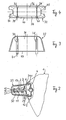
- Fig 1: eine Seitenansicht eines Außenrückspiegels mit Schutzkappe, teilweise im Vertikalschnitt;
- Fig. 2 eine Draufsicht auf einen Teil des Außenrückspie gels nach Fig. 1, teilweise im Horizontalschnitt;
- Fig. 3 einen Längsschnitt durch die Schutzkappe; und
- Fig. 4 eine Ansicht der Schutzkappe von innen.
- 1: a side view of an exterior rear-view mirror with protective cap, partly in vertical section;
- Fig. 2 is a plan view of part of the Außenrückspie gel of Figure 1, partially in horizontal section.
- 3 shows a longitudinal section through the protective cap; and
- Fig. 4 is a view of the protective cap from the inside.
Das im Ganzen mit 1 bezeichnete Spiegelgehäuse umschließt in an sich bekannter Weise einen nicht dargestellten Spiegel, der gemäß Fig. 1 von rechts zur Betrachtung freiliegt. Das Spiegelgehäuse 1 ist in noch zu beschreibender Weise an einem in allgemeinen mittleren Abschnitt 2 eines Haltebügels befestigt, der etwa die in der Gebrauchsmusterschrift G 82 09 925.1 oder die in der europäischen Patentanmeldung 86114485.5 dargestellte Form haben kann. Die beiden freien Enden des Haltebügels sind dazu bestimmt, wie insbsondere in der letztgenannten Schrift beschrieben, an der Fahrertür eines Fahrzeugs, insbesondere Lastkrafwagens oder Omnibusses, befestigt zu werden.The mirror housing, designated as a whole by 1, encloses, in a manner known per se, a mirror, not shown, which, according to FIG. 1, is exposed for viewing from the right. The mirror housing 1 is fastened in a manner yet to be described to a generally
Ein hinterer, in Gebrauchslage des Außenrückspiegels in Fahrtrichtung weisender Teil 3 des Spiegelgehäuses 1 enthält ein Tragrohr 4, welches mittels nicht dargestellter Schellen an einem Zwischenboden 5 des Spiegelgehäuses 1 dauerhaft befestigt ist. An das Tragrohr 4 ist in seinem mittleren Abschnitt eine bügelförmige Lasche 6 angeschweißt, welche vom Tragrohr 4 nach rückwärts absteht und mit einem außeren Abschnitt 7 aus einer mittleren Öffnung 8 des hinteren Teils 3 vorsteht. Wie in Fig. 1 zu erkennen ist, ist der äußere Abschnitt 7 leicht nach rückwärts gebogen und von dem Tragrohr 4 beabstandet. Die ebene, aus stahlgefertigte Lasche 6 ist im wesentlichen symmetrisch zu einer Mittellinie 9. Beiderseits der Mittellinie 9 durchdringt die Lasche je ein Durchgangsloch für noch zu erläuternde Bolzen.A rear part 3 of the mirror housing 1 pointing in the direction of travel in the position of use of the exterior rear-view mirror contains a support tube 4 which is permanently fastened to an
Die im Ganzen mit 10 bezeichnete Befestigungsvorrichtung, mittels der das Spiegelgehäuse am Abschnitt 2 festgeklemmt ist, umfaßt ferner zwei gleich große, im wesentlichen plattenförmige Klemmstücke, nämlich ein erstes Klemmstück 12 und ein zweites Klemmstück 14. Das erste Klemmstück 12 besitzt, symmetrisch zur Mittellinie 9, zwei in Richtung des Abschnitts 2 beabstandete Durchgangslöcher an dem von der Lasche 6 entfernt liegenden Rand 13 und einen gebogenen ersten Längsschlitz 22, der sich beiderseits der Mittellinie 9 symmetrisch zu dieser in dem der Lasche 6 benachbarten Teil des ersten Klemmstücks 12 erstreckt. Der Krümmungsmittelpunkt der kreisbogenförmigen Form des Längsschlitzes 22 liegt innerhalb des Spiegelgehäuses etwa im Bereich des nicht dargestellten Spiegels und ist mit 23 bezeichnet. In einem Zwischenabschnitt des ersten Klemmstücks 12 zwischen den Durchgangslöchern und dem Längsschlitz 22 ist eine Längsrinne 17 von solcher Form geprägt, daß sie an der Außenkontour des Abschnitts 2 flächig über etwa den halben Umfang anliegen kann.The fastening device designated as a whole by 10, by means of which the mirror housing is clamped to
Das zweite Klemmstück 14 besitzt mit den Durchgangsbohrungen des ersten Klemmstücks 12 fluchtende Durchgangsbohrungen sowie einen zweiten Längsschlitz 24, der genauso lang ist und in gleicher Weise gebogen ist wie der erste Längsschlitz 22. Auch liegt der Krümmungsmittelpunkt des zweiten Längsschlitzes am Krümmungsmittelpunkt 23. Hervorzuheben ist, daß die gesamte Länge jedes der beiden Längsschlitzes 22, 24 größer ist als der Abstand der Durchgangsbohrungen der Lasche 6. Wie in Fig. 1 dargestellt erstrecken sich beide Längsschlitze 22, 24 etwa symmetrisch zur Mittellinie 9.The
Ein Zwischenabschnitt des zweiten im wesentlich plattenförmigen Klemmstücks 14 zwischen den Durchgangsbohrungen des Klemmstücks 14 und dem zweiten Längsschlitz 24 ist zu einer zweiten Längsrinne 19 geformt, welche die Außenkontour des Abschnitts 2 im wesentlichen flächig um die Hälfte des Umfangs des Abschnitts 2 umfassen kann.An intermediate section of the second substantially plate-
Auf dem Abschnitt 2 ist über eine Länge, die wenigstens gleich der Länge der ersten Längsrinne 17 und der zweiten Längsrinne 19 ist, eine Kunststoffhülle 30 aufgeschrumpft, die zum Schutz der Lackierung des Abschnitts 2 dient.On the
Zur Montage des Spiegelgehäuses 1 am Abschnitt 2 wird ein erster Bolzen 25 durch ein erstes Paar fluchtender Durchgangsbohrungen in den Klemmstücken 12, 14 sowie ein zweiter Bolzen 26 durch das zweite Paar Durchgangsbohrungen in den Klemmstücken 12, 14 hindurchgeführt. Jeder der beiden Bolzen wird durch eine von seinem freien Ende her aufgeschraubte Mutter 21 gesichert. Ein dritter Bolzen 27 wird durch den ersten Längsschlitz 22, die erste Durchgangsbohrung in der Lasche 6 und durch den zweiten Längsschlitz 24 geführt und durch eine Mutter 29 gesichert. Schließlich wird ein vierter Bolzen 28 durch den ersten Längsschlitz 22, die zweite Durchgangsbohrung in der Lasche 6 und durch den zweiten Längsschlitz 24 geführt und mit einer Mutter gesichert. Wenn alle vier Bolzen und Muttern angezogen werden, wie Fig. 2 darstellt, erstreckt sich die Lasche zwischen die spiegelgehäusenahen Abschnitte der Klemmstücke 12, 14 und beide Klemmstücke umfassen zwischen sich den Abschnitt 2 an dessen Umfang unter Zwischenlage der erwähnten Hülle 30. Man entnimmt der Fig. 1, daß die Bolzen 27, 28 längs des Abschnittes 2 etwa um die Hälfte der Länge der Längsschlitze 22, 24 beabstandet sind. Die Bolzen 25, 26 können wie dargestellt einen größeren Abstand zueinander aufweisen. Das Spiegelgehäuse 1 ist auf diese Weise fest an dem Abschnitt 2 angeklemmt.To mount the mirror housing 1 on
Soll das Spiegelgehäuse in Anpassung an eine veränderte Sitzposition des nicht dargestellten Fahrers beispielsweise nach oben relativ zum Abschnitt 2 verschwenkt und dann arretiert werden, werden die Bolzen 27, 28 soweit gelockert, daß das Spiegelgehäuse 1 mit Lasche 6 entsprechend nach oben verschwenkt werden kann, wobei die Bolzen 27, 28 in den Längsschlitzen 22, 24 nach unten wandern. Nach Erreichen der gewünschten Schwenklage werden die Bolzen 27, 28 wieder angezogen. Wie aus in Figuren 1 und 2 zu erkennen ist, befinden sich die Bolzen 27, 28 außerhalb der Öffnung 8 und sind daher von außen frei zugänglich.If the mirror housing is to be pivoted upwards relative to
Um die Befestigungsvorrichtung 10 und das Innere des hinteren Teils 3 vor Witterungseinflüssen zu schützen, ist eine Schutzkappe 32 vorgesehen, welche die Klemmstücke 12, 14 und die Öffnung 8, und damit auch die Lasche 6 überdeckt. Aus den gegenüberliegenden Innenwänden 34, 36 sind je ein Paar in Längsrichtung der Schutzkappe 32 beabstandete, einwärts federnde Finger 37, 38, 39, 40 angeformt, welche an ihren freien Enden auswärts weisende Haken 41, 42 besitzen. Die Haken 41, 42 können den Rand der Öffnung 8 unter Spannung untergreifen derart, daß der untere Rand 43 der Schutzkappe 32 satt auf dem äußeren Rand der Öffnung 8 aufliegt. Die Schutzkappe 32 besitzt in den gegenüberliegenden schmaleren Seitenwänden 44, 45 je einen vom Rand 40 ausgehenden tiefen Einschnitt, der den Durchtritt des Abschnittes 2 durch die Seitenwände 44, 45 erlaubt.In order to protect the
Wie dargestellt sind die Längsschlitze 22, 24 bezüglich des Spiegelgehäuses 1 konkav gebogen; es liegt natürlich im Rahmen der Erfindung, den Längsschlitzen 22, 24 auch eine konvexe Krümmung zu geben, so daß der Krümmungsmittelpunkt dann auf der dem Spiegelgehäuse 1 gegenüberliegenden Seite des Abschnitts 2 liegt.As shown, the
Der Schwenkbereich des Spiegelgehäuses 1 relativ zum Abschnitt 2 ist durch die Länge der Längsschlitze 22, 24 bestimmt und beträgt etwa 10 Grad zu jeder Seite der Mittellinie 9.The pivoting range of the mirror housing 1 relative to the
Claims (8)
Priority Applications (1)
| Application Number | Priority Date | Filing Date | Title |
|---|---|---|---|
| AT88118886T ATE79088T1 (en) | 1987-12-05 | 1988-11-12 | HINGED EXTERIOR REAR-VIEW MIRROR ESPECIALLY FOR TRUCKS. |
Applications Claiming Priority (2)
| Application Number | Priority Date | Filing Date | Title |
|---|---|---|---|
| DE8716105U DE8716105U1 (en) | 1987-12-05 | 1987-12-05 | |
| DE8716105U | 1987-12-05 |
Publications (2)
| Publication Number | Publication Date |
|---|---|
| EP0319735A1 true EP0319735A1 (en) | 1989-06-14 |
| EP0319735B1 EP0319735B1 (en) | 1992-08-05 |
Family
ID=6814801
Family Applications (1)
| Application Number | Title | Priority Date | Filing Date |
|---|---|---|---|
| EP88118886A Expired - Lifetime EP0319735B1 (en) | 1987-12-05 | 1988-11-12 | Swingable exterior rear-view mirror, especially for lorries |
Country Status (7)
| Country | Link |
|---|---|
| US (1) | US4909619A (en) |
| EP (1) | EP0319735B1 (en) |
| AT (1) | ATE79088T1 (en) |
| CA (1) | CA1324280C (en) |
| DE (2) | DE8716105U1 (en) |
| ES (1) | ES2034118T3 (en) |
| MX (1) | MX170210B (en) |
Cited By (3)
| Publication number | Priority date | Publication date | Assignee | Title |
|---|---|---|---|---|
| CN105946721A (en) * | 2016-06-27 | 2016-09-21 | 徐州徐工矿山机械有限公司 | Rear view mirror bracket for mining dump vehicle |
| CN105946722A (en) * | 2016-06-27 | 2016-09-21 | 徐州徐工矿山机械有限公司 | Rear view mirror bracket for mining dump vehicle |
| CN111301288A (en) * | 2019-11-18 | 2020-06-19 | 深圳市君厚财税服务有限公司 | New energy automobile rearview mirror is used in maintenance convenient to dismantle |
Families Citing this family (11)
| Publication number | Priority date | Publication date | Assignee | Title |
|---|---|---|---|---|
| US5028029A (en) * | 1990-03-09 | 1991-07-02 | Delbar Products, Inc. | Mirror swing lock mechanism |
| US5039055A (en) * | 1990-09-17 | 1991-08-13 | Luverne Truck Equipt. Inc. | Adjustable and extendable mount for rear view mirror |
| US5576899A (en) * | 1991-06-03 | 1996-11-19 | Rosco, Inc. | Mirror mount for vehicles |
| US5386312A (en) * | 1992-08-03 | 1995-01-31 | Hughes Aircraft Company | Collimating lens having doublet element between positive-power elements |
| US5623374A (en) * | 1994-03-15 | 1997-04-22 | Adac Plastics, Inc. | Spring detent for foldable side mount rear view mirror |
| DE9414268U1 (en) * | 1994-09-02 | 1994-10-27 | Kaessbohrer Fahrzeug Karl | Vehicle exterior mirror |
| DE10064647A1 (en) * | 2000-12-22 | 2002-07-11 | Mekra Lang Gmbh & Co Kg | Rearview mirror, in particular for motor vehicles |
| US8157394B1 (en) * | 2009-10-07 | 2012-04-17 | William Downing | Attachable adjustable mirror |
| DE202010009347U1 (en) * | 2010-01-20 | 2011-06-01 | MEKRA Lang GmbH & Co. KG, 90765 | Adapter for precise fitting and position fixing of a mirror unit |
| US9663037B2 (en) | 2015-08-12 | 2017-05-30 | Caterpillar Inc. | Multi-stage swing arm mirror mount |
| CN112193162A (en) * | 2020-09-28 | 2021-01-08 | 重庆长安工业(集团)有限责任公司 | Anti-impact vibration-reduction rearview mirror for armored vehicle |
Citations (4)
| Publication number | Priority date | Publication date | Assignee | Title |
|---|---|---|---|---|
| US1358159A (en) * | 1920-03-09 | 1920-11-09 | Kern John | Reflector-mounting |
| GB1327383A (en) * | 1970-08-25 | 1973-08-22 | Desmo Ltd | Vehicle rearview driving mirror assemblies |
| FR2227152A1 (en) * | 1973-04-27 | 1974-11-22 | Wingard Ltd | |
| FR2552175A1 (en) * | 1983-09-15 | 1985-03-22 | Gerard Perard | Clamp for reinforcement structures of vehicles |
Family Cites Families (5)
| Publication number | Priority date | Publication date | Assignee | Title |
|---|---|---|---|---|
| US3377117A (en) * | 1963-10-28 | 1968-04-09 | Edgar B. Biscow | Rear view mirror assembly including a sleeve having an internal spring to restore the reflector to a given position |
| DE8209925U1 (en) * | 1982-04-07 | 1982-07-29 | MEKRA Rangau Plastics GmbH & Co KG, 8510 Fürth | Pivoting rearview mirror that can be adjusted by motor around a vertical axis |
| EP0090909A3 (en) * | 1982-04-07 | 1985-05-22 | MEKRA Rangau Plastics GmbH & Co KG | Motor driven adjustable rear mirror |
| CA1172081A (en) * | 1982-04-30 | 1984-08-07 | Benjamin Bronstein | Rear view mirror extension device |
| DE3544836A1 (en) * | 1985-12-18 | 1987-06-19 | Man Nutzfahrzeuge Gmbh | VEHICLE EXTERIOR MIRROR MOUNT |
-
1987
- 1987-12-05 DE DE8716105U patent/DE8716105U1/de not_active Expired
-
1988
- 1988-11-12 ES ES198888118886T patent/ES2034118T3/en not_active Expired - Lifetime
- 1988-11-12 EP EP88118886A patent/EP0319735B1/en not_active Expired - Lifetime
- 1988-11-12 DE DE8888118886T patent/DE3873497D1/en not_active Expired - Fee Related
- 1988-11-12 AT AT88118886T patent/ATE79088T1/en not_active IP Right Cessation
- 1988-12-01 CA CA000584660A patent/CA1324280C/en not_active Expired - Fee Related
- 1988-12-05 MX MX1405288A patent/MX170210B/en unknown
- 1988-12-05 US US07/279,811 patent/US4909619A/en not_active Expired - Fee Related
Patent Citations (4)
| Publication number | Priority date | Publication date | Assignee | Title |
|---|---|---|---|---|
| US1358159A (en) * | 1920-03-09 | 1920-11-09 | Kern John | Reflector-mounting |
| GB1327383A (en) * | 1970-08-25 | 1973-08-22 | Desmo Ltd | Vehicle rearview driving mirror assemblies |
| FR2227152A1 (en) * | 1973-04-27 | 1974-11-22 | Wingard Ltd | |
| FR2552175A1 (en) * | 1983-09-15 | 1985-03-22 | Gerard Perard | Clamp for reinforcement structures of vehicles |
Cited By (4)
| Publication number | Priority date | Publication date | Assignee | Title |
|---|---|---|---|---|
| CN105946721A (en) * | 2016-06-27 | 2016-09-21 | 徐州徐工矿山机械有限公司 | Rear view mirror bracket for mining dump vehicle |
| CN105946722A (en) * | 2016-06-27 | 2016-09-21 | 徐州徐工矿山机械有限公司 | Rear view mirror bracket for mining dump vehicle |
| CN105946722B (en) * | 2016-06-27 | 2018-02-09 | 徐州徐工矿山机械有限公司 | A kind of driving mirror bracket for quarry tipper |
| CN111301288A (en) * | 2019-11-18 | 2020-06-19 | 深圳市君厚财税服务有限公司 | New energy automobile rearview mirror is used in maintenance convenient to dismantle |
Also Published As
| Publication number | Publication date |
|---|---|
| DE3873497D1 (en) | 1992-09-10 |
| MX170210B (en) | 1993-08-11 |
| CA1324280C (en) | 1993-11-16 |
| US4909619A (en) | 1990-03-20 |
| ES2034118T3 (en) | 1993-04-01 |
| EP0319735B1 (en) | 1992-08-05 |
| DE8716105U1 (en) | 1988-03-03 |
| ATE79088T1 (en) | 1992-08-15 |
Similar Documents
| Publication | Publication Date | Title |
|---|---|---|
| EP0319735B1 (en) | Swingable exterior rear-view mirror, especially for lorries | |
| DE2824354A1 (en) | DEVICE FOR IMPROVING VISIBILITY ON CARS | |
| EP0900713A1 (en) | Motor vehicle with bottom sub-unit | |
| DE10141010A1 (en) | Locking device with an operating lever for an adjustable steering column | |
| DE102010010585B4 (en) | Longitudinal adjuster for a vehicle seat with spindle and spindle holder | |
| CH620866A5 (en) | ||
| EP1008468B1 (en) | Mounting for drawbar | |
| DE2642475C3 (en) | Guardrail | |
| EP0806325A1 (en) | Belt tensioner | |
| DE1903331B1 (en) | Bumper for motor vehicles | |
| DE2342365C3 (en) | Mud flaps | |
| DE3032870A1 (en) | DRAIN CATCHER FOR VEHICLES | |
| DE102018132229A1 (en) | Adjustable seat assembly for a motorcycle and motorcycle | |
| DE4304920A1 (en) | Fore carriage for road vehicle - has on each side one-armed longitudinal bearer with downwardly angled area beneath cross wall | |
| EP0411262A1 (en) | Adjustable mud-guard for the steerable wheels of a vehicle | |
| DE2642110C2 (en) | ||
| EP0557767B1 (en) | Adjustable steering column for motor vehicles | |
| DE102005062046B3 (en) | Removable additional external mirror for motor vehicle has vice-like clamp part that has at least one clamping element and that is connected to additional external mirror housing | |
| DE3503966A1 (en) | VEHICLE WING DOOR | |
| DE1928832C3 (en) | Carrying device for the spare wheel of a motor vehicle | |
| EP3453236A1 (en) | Mounting plate unit | |
| DE3727203A1 (en) | Sidewall protection device for a motor vehicle | |
| EP4051559B1 (en) | Modular system and connection device for motor vehicle air-guiding elements | |
| DE2556604A1 (en) | DETACHABLE PAIR OF REAR MIRRORS | |
| EP0470526A2 (en) | Device for mounting a rubber-sprung axle on the frame of a vehicle |
Legal Events
| Date | Code | Title | Description |
|---|---|---|---|
| PUAI | Public reference made under article 153(3) epc to a published international application that has entered the european phase |
Free format text: ORIGINAL CODE: 0009012 |
|
| AK | Designated contracting states |
Kind code of ref document: A1 Designated state(s): AT BE CH DE ES FR GB IT LI LU NL SE |
|
| 17P | Request for examination filed |
Effective date: 19891215 |
|
| 17Q | First examination report despatched |
Effective date: 19920123 |
|
| GRAA | (expected) grant |
Free format text: ORIGINAL CODE: 0009210 |
|
| AK | Designated contracting states |
Kind code of ref document: B1 Designated state(s): AT BE CH DE ES FR GB IT LI LU NL SE |
|
| REF | Corresponds to: |
Ref document number: 79088 Country of ref document: AT Date of ref document: 19920815 Kind code of ref document: T |
|
| REF | Corresponds to: |
Ref document number: 3873497 Country of ref document: DE Date of ref document: 19920910 |
|
| GBT | Gb: translation of ep patent filed (gb section 77(6)(a)/1977) | ||
| ET | Fr: translation filed | ||
| ITF | It: translation for a ep patent filed |
Owner name: UFFICIO TECNICO ING. A. MANNUCCI |
|
| REG | Reference to a national code |
Ref country code: ES Ref legal event code: FG2A Ref document number: 2034118 Country of ref document: ES Kind code of ref document: T3 |
|
| PLBE | No opposition filed within time limit |
Free format text: ORIGINAL CODE: 0009261 |
|
| STAA | Information on the status of an ep patent application or granted ep patent |
Free format text: STATUS: NO OPPOSITION FILED WITHIN TIME LIMIT |
|
| 26N | No opposition filed | ||
| PGFP | Annual fee paid to national office [announced via postgrant information from national office to epo] |
Ref country code: LU Payment date: 19931116 Year of fee payment: 6 |
|
| PGFP | Annual fee paid to national office [announced via postgrant information from national office to epo] |
Ref country code: AT Payment date: 19931125 Year of fee payment: 6 |
|
| PGFP | Annual fee paid to national office [announced via postgrant information from national office to epo] |
Ref country code: NL Payment date: 19931130 Year of fee payment: 6 |
|
| PGFP | Annual fee paid to national office [announced via postgrant information from national office to epo] |
Ref country code: BE Payment date: 19931206 Year of fee payment: 6 |
|
| PGFP | Annual fee paid to national office [announced via postgrant information from national office to epo] |
Ref country code: CH Payment date: 19931220 Year of fee payment: 6 |
|
| EPTA | Lu: last paid annual fee | ||
| PGFP | Annual fee paid to national office [announced via postgrant information from national office to epo] |
Ref country code: GB Payment date: 19941024 Year of fee payment: 7 |
|
| PG25 | Lapsed in a contracting state [announced via postgrant information from national office to epo] |
Ref country code: LU Free format text: LAPSE BECAUSE OF NON-PAYMENT OF DUE FEES Effective date: 19941112 Ref country code: AT Effective date: 19941112 |
|
| PGFP | Annual fee paid to national office [announced via postgrant information from national office to epo] |
Ref country code: FR Payment date: 19941117 Year of fee payment: 7 |
|
| PGFP | Annual fee paid to national office [announced via postgrant information from national office to epo] |
Ref country code: SE Payment date: 19941123 Year of fee payment: 7 |
|
| PG25 | Lapsed in a contracting state [announced via postgrant information from national office to epo] |
Ref country code: LI Effective date: 19941130 Ref country code: CH Effective date: 19941130 Ref country code: BE Effective date: 19941130 |
|
| PGFP | Annual fee paid to national office [announced via postgrant information from national office to epo] |
Ref country code: ES Payment date: 19941130 Year of fee payment: 7 Ref country code: DE Payment date: 19941130 Year of fee payment: 7 |
|
| EAL | Se: european patent in force in sweden |
Ref document number: 88118886.6 |
|
| BERE | Be: lapsed |
Owner name: HOHE K.G. Effective date: 19941130 |
|
| PG25 | Lapsed in a contracting state [announced via postgrant information from national office to epo] |
Ref country code: NL Effective date: 19950601 |
|
| NLV4 | Nl: lapsed or anulled due to non-payment of the annual fee | ||
| REG | Reference to a national code |
Ref country code: CH Ref legal event code: PL |
|
| PG25 | Lapsed in a contracting state [announced via postgrant information from national office to epo] |
Ref country code: GB Effective date: 19951112 |
|
| PG25 | Lapsed in a contracting state [announced via postgrant information from national office to epo] |
Ref country code: SE Effective date: 19951113 Ref country code: ES Free format text: LAPSE BECAUSE OF NON-PAYMENT OF DUE FEES Effective date: 19951113 |
|
| GBPC | Gb: european patent ceased through non-payment of renewal fee |
Effective date: 19951112 |
|
| PG25 | Lapsed in a contracting state [announced via postgrant information from national office to epo] |
Ref country code: FR Effective date: 19960731 |
|
| PG25 | Lapsed in a contracting state [announced via postgrant information from national office to epo] |
Ref country code: DE Effective date: 19960801 |
|
| EUG | Se: european patent has lapsed |
Ref document number: 88118886.6 |
|
| REG | Reference to a national code |
Ref country code: FR Ref legal event code: ST |
|
| REG | Reference to a national code |
Ref country code: ES Ref legal event code: FD2A Effective date: 19961213 |
|
| PG25 | Lapsed in a contracting state [announced via postgrant information from national office to epo] |
Ref country code: IT Free format text: LAPSE BECAUSE OF NON-PAYMENT OF DUE FEES;WARNING: LAPSES OF ITALIAN PATENTS WITH EFFECTIVE DATE BEFORE 2007 MAY HAVE OCCURRED AT ANY TIME BEFORE 2007. THE CORRECT EFFECTIVE DATE MAY BE DIFFERENT FROM THE ONE RECORDED. Effective date: 20051112 |