EP0319684A2 - Anzeigesystem für die Quantizierung von Farbbildern - Google Patents
Anzeigesystem für die Quantizierung von Farbbildern Download PDFInfo
- Publication number
- EP0319684A2 EP0319684A2 EP88117468A EP88117468A EP0319684A2 EP 0319684 A2 EP0319684 A2 EP 0319684A2 EP 88117468 A EP88117468 A EP 88117468A EP 88117468 A EP88117468 A EP 88117468A EP 0319684 A2 EP0319684 A2 EP 0319684A2
- Authority
- EP
- European Patent Office
- Prior art keywords
- color values
- color
- encoded
- values
- component
- Prior art date
- Legal status (The legal status is an assumption and is not a legal conclusion. Google has not performed a legal analysis and makes no representation as to the accuracy of the status listed.)
- Withdrawn
Links
- 238000013139 quantization Methods 0.000 title claims description 7
- 230000015654 memory Effects 0.000 claims abstract description 36
- 239000000872 buffer Substances 0.000 claims abstract description 34
- 230000001131 transforming effect Effects 0.000 claims abstract 2
- 239000003086 colorant Substances 0.000 claims description 27
- 238000013507 mapping Methods 0.000 claims description 10
- 238000001228 spectrum Methods 0.000 claims description 5
- 239000011159 matrix material Substances 0.000 claims 1
- 230000003595 spectral effect Effects 0.000 claims 1
- 238000012545 processing Methods 0.000 abstract description 2
- 230000009466 transformation Effects 0.000 abstract 1
- 238000000034 method Methods 0.000 description 7
- 230000008520 organization Effects 0.000 description 3
- 238000010586 diagram Methods 0.000 description 2
- 239000013598 vector Substances 0.000 description 2
- 239000000654 additive Substances 0.000 description 1
- 230000000996 additive effect Effects 0.000 description 1
- 238000013459 approach Methods 0.000 description 1
- 238000003491 array Methods 0.000 description 1
- 230000015556 catabolic process Effects 0.000 description 1
- 239000000470 constituent Substances 0.000 description 1
- 238000006731 degradation reaction Methods 0.000 description 1
- 230000001419 dependent effect Effects 0.000 description 1
- 238000011161 development Methods 0.000 description 1
- 230000018109 developmental process Effects 0.000 description 1
- 230000008672 reprogramming Effects 0.000 description 1
- 239000004065 semiconductor Substances 0.000 description 1
- XLYOFNOQVPJJNP-UHFFFAOYSA-N water Substances O XLYOFNOQVPJJNP-UHFFFAOYSA-N 0.000 description 1
Images


Classifications
-
- G—PHYSICS
- G09—EDUCATION; CRYPTOGRAPHY; DISPLAY; ADVERTISING; SEALS
- G09G—ARRANGEMENTS OR CIRCUITS FOR CONTROL OF INDICATING DEVICES USING STATIC MEANS TO PRESENT VARIABLE INFORMATION
- G09G5/00—Control arrangements or circuits for visual indicators common to cathode-ray tube indicators and other visual indicators
- G09G5/02—Control arrangements or circuits for visual indicators common to cathode-ray tube indicators and other visual indicators characterised by the way in which colour is displayed
- G09G5/06—Control arrangements or circuits for visual indicators common to cathode-ray tube indicators and other visual indicators characterised by the way in which colour is displayed using colour palettes, e.g. look-up tables
-
- G—PHYSICS
- G09—EDUCATION; CRYPTOGRAPHY; DISPLAY; ADVERTISING; SEALS
- G09G—ARRANGEMENTS OR CIRCUITS FOR CONTROL OF INDICATING DEVICES USING STATIC MEANS TO PRESENT VARIABLE INFORMATION
- G09G5/00—Control arrangements or circuits for visual indicators common to cathode-ray tube indicators and other visual indicators
- G09G5/02—Control arrangements or circuits for visual indicators common to cathode-ray tube indicators and other visual indicators characterised by the way in which colour is displayed
- G09G5/022—Control arrangements or circuits for visual indicators common to cathode-ray tube indicators and other visual indicators characterised by the way in which colour is displayed using memory planes
Definitions
- the invention relates to apparatus for displaying color images in digital maps, and more particularly to an apparatus for quantizing color images for use with a frame buffer display.
- Raster scan systems which provide a bit-mapped memory for extracting graphic images in line-by-line and pixel-by-pixel format in synchronism with a timing signal are well known in the graphics display art.
- the video images are mapped into the display memory addresses in accordance with pixel locations on the face of the display.
- the raster lines are then recovered directly from the display memory by sequentially accessing the bytes stored therein, transferring them to a buffer, and feeding the output of the buffer to modulate the intensity of the corresponding pixel.
- the display memory for a 512-by-512 pixel array must support over 250,000 pixel locations.
- the graphics controller is required to generate pixel color values at a rate commensurate with the resolution and frame refresh rate of the display.
- a monochromatic display for a 512-by-512 pixel array refreshed at 30 Hz must access data from memory and process the data to provide display signal amplitudes at a rate of about 8 million pixel values per second.
- a multiple bit word is required to define the color state of each pixel.
- the present invention as defined in the independent claims provides an improved apparatus for displaying color images requiring multiple buffers and memory planes, while minimizing the image buffer size to that required by a pseudocolor diaplay system.
- a pseudocolor display system is defined as one on which video images may not need a full spectrum of colors, and therefore the number of colors and their respective intensity levels may be predefined. This is true, for example, with a digital map display, where the application of colors to define symbols and terrain features is well defined, as in conventional paper maps, or in image enhancement applications where it is desired to create a pseudocolor display of a monochromatic image. Preferred details of the invention are described in the dependent claims.
- the invention includes a video generator for supplying full-spectrum color images in a plurality of displayable R-G-B color values, coupled to a lookup table, wherein are encoded in pseudocolor format a reduced number of color values corresponding to neighboring values of the full-spectrum display.
- the lookup table is so constructed that an address corresponding to any of the displayable color values will access the closet neighboring color in pseudocolor format.
- the table is addressed by the video source and the encoded color values stored in a frame buffer. When the buffer is filled, the output is sequentially applied to a decoder which converts the encoded word stored in the buffer to a displayable R-G-B color value.
- the size of the data word which describes the color value of each pixel is a key factor in determining the total memory size of the buffer. Since the number of bits of each data. word is multiplied by the X-Y pixel extent (e.g., 512 x 512 pixels), even a relatively small data word requires a substantial memory size.
- the capabilities of a graphics system may be significantly expanded.
- the bits for each pixel in a bit-mapped memory may be accessed in parallel to form a multi-bit pixel word.
- the most general application for multiple memory planes is to create intermediate gray shades on a monochromatic display or multiple colors on a color display.
- eight display memory planes will produce an 8-bit word that defines up to 256 shades of grey, which when applied to a digital-to-analog convertor (DAC) can be used to modulate the beam intensity of a cathode ray tube accordingly.
- Three planes, one assigned to each of the red, green, and blue primary colors, can generate eight colors, by mixing the primary color components.
- two planes per color would permit generating four intensities per color, thus providing a total of 64 color values on the display face.
- R-G-B red, green, blue
- Figure 1c shows an R-G-B frame buffer memory organized as three groups of five memory planes.
- each group provides a 5-bit pixel descriptor to characterize a primary color component, and the 15-bit output thereby yields a spectrum of 32,768 colors, but requires a substantial memory capacity. While costs are falling rapidly for semiconductor memories, suitable high reliability components, particularly for military-grade applications, still pose significant problems of cost and size.
- a second approach is a pseudocolor format, as shown in Figure ld.
- the buffer-memory of raster displays may include a video lookup table.
- the value of a pixel is not routed directly to the display device, but is instead used to address a lookup table, which is an auxiliary memory programmed with a predetermined set of a reduced number of colors.
- the pixel address is used to control the color value of the display face.
- the lookup table must have as many storage spaces as there are displayable pixels, it may characterize a reduced number of colors by a smaller pixel descriptor than is applied to address the table. Further, by using.a programmable memory (PROM), the table entries may be dynamically changed, for example, to expand a color range or reflect a change in application.
- Figure 1d shows a programmable pseudocolor display employing eight memory planes to generate an eight-bit pixel descriptor. The memory output is applied to a 256 entry lookup table which provides red, green, and blue color outputs of 5-bit word size.
- the present invention provides an apparatus for accessing a lookup table encoded in pseudocolor format and providing an output in R-G-B format.
- Encoding a pseudocolor lookup table requires quantization of the color values in a video image. It may be defined as the process of assigning representation values to ranges of input values (Heckbert, P., "Color Image Quantization for Frame Buffer Display", Association of Computing Machinery , V. 16, No. 3 (July 1982), 297- 307. Color image quantization is the process of selecting a set of colors to represent the color gamut of an image, and computing the mapping from color space to representative colors. Thus, many color images which would otherwise require a frame buffer having 15 bits per pixel can be quantized to 8 or fewer bits per pixel with little observable degradation.
- the color quantization task may be broken into four phases:
- a 256 word color set is defined to form a table.
- Column A represents the entry number from 0 to 255
- column B the corresponding color reference number
- columns C, D, and E represent the corresponding red-green-blue color constituent of the desired color set in binary format.
- Each color combination corresponds to an arbitrary 8-bit hue-intensity descriptor.
- Three bits are used to identify a hue and provide 8 different hues (column F) and 5 bits to describe an intensity value of that hue providing 32 degrees of intensity shading (column G).
- An 8-bit buffer memory is assumed for this example, and a fixed value of saturation.
- a typical selection of corresponding colors is defined in column H.
- R-G-B and H-I-S descriptors are well known in the art and may be determined by mathematical relationships, as shown, for example, in "Raster Graphics Handbook", Conrac Corporation, Van Nostrand Reinhold Company, NY 2d Ed. 1985, 335-338, it is simpler to use an arbitrary 8 bit description, since the decoder may be programmed with a similar definition to regenerate the original R-G-B color values.
- Each 8-bit word corresponding to columns F and G defines a predetermined color value in terms of variable hue and intensity into which the 15 bit R-G-B video image is to be mapped.
- the color set defined must have all of the colors the system is required to generate. However, it is clear to one skilled in the art that by using a dynamically programmable memory for the lookup table, these values may be changed.
- the R-G-B representation of the video image provides a total of 32,768 color combinations. Therefore, the encoder lookup table must be capable of being addressed by all 32,768 color commands.
- the encoder lookup table will be comprised of a 32K by 8 bit memory. Since, for example, a set of only 256 predetermined color values is stored in the encoder lookup table, in the form of 8-bit words describing hue and intensity, all addresses which do not expressly correspond to one of the predetermined colors will be assigned to one of 256 colors, based on the nearest color neighbor, as described below.
- FIG. 3a shows a conceptual linear model of the color space, treating R, G, and B as vectors, and the origin O as white. While in practice equal components of the primary color components will not result in white, the model is adequate to illustrate the principles of the invention.
- Figure 3b there is shown a plurality of dots, each dot representing one of the 32,768 color states available for a 5-bit R-G-B descriptor.
- Figure 3c the small circles are representative of selected colors in a defined 256 state color set. Adjoining each of the 256 color states is a group of neighboring color states comprising the totality of 32,768 color states of Figure 4b.
- the process of determining the nearest neighbor mapping need be computed only once for a particular application.
- the resulting values are then stored in the lookup table, which can be accessed at video rates to provide real time displays.
- R x , G x , B x are the predetermined values in the color set of 256 colors.
- d is the color "distance" to be minimized.
- the 5-bit r-g-b color states are applied to address the lookup table.
- an 8-bit word is encoded with a hue and intensity value equivalent to one of the 256 R-G-B color states.
- a value of d is computed.
- a family of 256 values of d is solved, from which the minimum "d" is selected for the table to correspond to the PROM address of r y , g y , b y .
- the results may be tabulated so that each of the 256 color states is representative of a plurality of neighboring color states for which d is minimized.
- the lookup table is then encoded with these values. In operation, when the lookup table is addressed by a 15-bit r,g,b output of the video source, the nearest 8-bit value in the defined color set R,G,B will be accessed, without intermediate computations or processing.
- a video image 10 in digital form is applied to transform 12 to a generate a 15-bit color signal.
- the signal is preferably in R-G-B format, although it may also be transformed to hue, intensity and saturation (H-I-S) values.
- H-I-S hue, intensity and saturation
- a system using a 5 bit color descriptor provides 32 different color values for each primary color, although this is exemplary, and not to be construed as limiting.
- a lookup table is encoded in programmable memory 16, which may be a 32K x 8 PROM, such as type 27256 UV erasable PROM, manufactured by Intel Corporation.
- Lookup table 16 is addressed by the 15-bit output and provides an 8-bit word corresponding to the color value of the nearest neighbor in the 256 word color set to a frame buffer 20.
- the stored values are extracted by the raster scan electronics (not shown) and applied to a further lookup table 22, which decomposes the encoded format back to the R-G-B color components to drive the display.
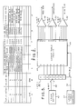
- Figure 5 shows the circuit for decoding the 8-bit output of the frame buffer for driving the red, green, and blue exciting elements of a display; for example, the electron guns of a cathode ray tube.
- the frame buffer 40 feeds via an 8-bit bus 46 a latch 42, which stores the 8-bit color word and addresses a 256 x 15 lookup table 44.
- Table 44 may be comprised of three 5-bit x 256 word sections. Each section corresponds to one of the R-G-B color components of the 256 value color set.
- Table 44 is encoded identically with the color set of Figure 2, columns C, D, E and addressed in accordance with column F and G thereof.
- lookup table 44 For each of the 256 combinations of hue and intensity represented by the 8-bit address on bus 46, a location will be selected in lookup table 44 that provides the corresponding quantized red, green, and blue color components of the encoded video image.
- the digital outputs of table 44 are applied to digital-to-analog convertors 48, 50, and 52, which convert the respective 5 digit inputs to one of 32 analog levels for modulating a corresponding color gun or pixel color value.
- the lookup table generator 54 optionally permits reprogramming table 44 by gating out the signals from frame buffer 40 and applying a revised data table via data bus 56.
Landscapes
- Engineering & Computer Science (AREA)
- Physics & Mathematics (AREA)
- Computer Hardware Design (AREA)
- General Physics & Mathematics (AREA)
- Theoretical Computer Science (AREA)
- Controls And Circuits For Display Device (AREA)
- Digital Computer Display Output (AREA)
- Image Generation (AREA)
- Color Television Systems (AREA)
Applications Claiming Priority (2)
| Application Number | Priority Date | Filing Date | Title |
|---|---|---|---|
| US11188787A | 1987-10-23 | 1987-10-23 | |
| US111887 | 1987-10-23 |
Publications (2)
| Publication Number | Publication Date |
|---|---|
| EP0319684A2 true EP0319684A2 (de) | 1989-06-14 |
| EP0319684A3 EP0319684A3 (de) | 1991-02-06 |
Family
ID=22340973
Family Applications (1)
| Application Number | Title | Priority Date | Filing Date |
|---|---|---|---|
| EP19880117468 Withdrawn EP0319684A3 (de) | 1987-10-23 | 1988-10-20 | Anzeigesystem für die Quantizierung von Farbbildern |
Country Status (3)
| Country | Link |
|---|---|
| EP (1) | EP0319684A3 (de) |
| JP (1) | JPH0292A (de) |
| IL (1) | IL88097A0 (de) |
Cited By (4)
| Publication number | Priority date | Publication date | Assignee | Title |
|---|---|---|---|---|
| EP0445388A3 (en) * | 1990-03-09 | 1992-08-05 | International Business Machines Corporation | Apparatus and method for compressing and expanding multibit digital pixel data |
| EP0465102B1 (de) * | 1990-06-27 | 1996-01-03 | Texas Instruments Incorporated | Palettengeräte mit Selektion von vielfachen die gesamte Busbreite enthaltenden Pixeltiefen |
| GB2371730B (en) * | 2000-10-23 | 2005-03-23 | Nec Corp | Image data storage |
| EP1887785A1 (de) * | 2006-08-04 | 2008-02-13 | Nederlandse Organisatie voor Toegepast-Natuuurwetenschappelijk Onderzoek TNO | Verfahren und Vorrichtung zum Konvertieren von mindestens einem Bild eines ersten Spektrums in ein Bild eines zweiten Spektrums |
Families Citing this family (4)
| Publication number | Priority date | Publication date | Assignee | Title |
|---|---|---|---|---|
| JPH04261796A (ja) * | 1991-02-13 | 1992-09-17 | Nachi Fujikoshi Corp | ホース内蔵型ロボットアーム |
| JP3138838B2 (ja) * | 1992-04-30 | 2001-02-26 | 東レ・ダウコーニング・シリコーン株式会社 | 混合粉体の製造方法 |
| CN100579242C (zh) * | 2006-08-29 | 2010-01-06 | 扬智科技股份有限公司 | 色彩快速简化方法 |
| JP5523812B2 (ja) | 2009-12-16 | 2014-06-18 | 株式会社リコー | 混練装置及びトナー製造方法 |
Family Cites Families (2)
| Publication number | Priority date | Publication date | Assignee | Title |
|---|---|---|---|---|
| DE3326069A1 (de) * | 1983-07-20 | 1985-02-07 | Dornier System Gmbh, 7990 Friedrichshafen | Einrichtung zur umsetzung von farbfernsehbildern in rastergrafiken mit begrenzter rasteraufloesung und mit begrenzter anzahl von gleichzeitig benutzbaren farbtoenen |
| JPS61107392A (ja) * | 1984-10-31 | 1986-05-26 | 株式会社東芝 | 画像処理システム |
-
1988
- 1988-10-20 IL IL8888097A patent/IL88097A0/xx unknown
- 1988-10-20 EP EP19880117468 patent/EP0319684A3/de not_active Withdrawn
- 1988-10-24 JP JP63266273A patent/JPH0292A/ja active Pending
Cited By (8)
| Publication number | Priority date | Publication date | Assignee | Title |
|---|---|---|---|---|
| EP0445388A3 (en) * | 1990-03-09 | 1992-08-05 | International Business Machines Corporation | Apparatus and method for compressing and expanding multibit digital pixel data |
| EP0465102B1 (de) * | 1990-06-27 | 1996-01-03 | Texas Instruments Incorporated | Palettengeräte mit Selektion von vielfachen die gesamte Busbreite enthaltenden Pixeltiefen |
| GB2371730B (en) * | 2000-10-23 | 2005-03-23 | Nec Corp | Image data storage |
| US6900815B2 (en) | 2000-10-23 | 2005-05-31 | Nec Corporation | Image data storage method |
| EP1887785A1 (de) * | 2006-08-04 | 2008-02-13 | Nederlandse Organisatie voor Toegepast-Natuuurwetenschappelijk Onderzoek TNO | Verfahren und Vorrichtung zum Konvertieren von mindestens einem Bild eines ersten Spektrums in ein Bild eines zweiten Spektrums |
| WO2008016305A3 (en) * | 2006-08-04 | 2008-05-29 | Tno | Method and system for converting at least one first-spectrum image into a second-spectrum image |
| JP2009545804A (ja) * | 2006-08-04 | 2009-12-24 | ネーデルランツ オルガニサティー フォール トゥーゲパストナトゥールヴェテンシャッペリーク オンデルズーク テーエンオー | 少なくとも1つの第1スペクトル画像を第2スペクトル画像に変換する方法およびシステム |
| US8478028B2 (en) | 2006-08-04 | 2013-07-02 | Nederlandse Organisatie Voor Toegepast-Natuurwetenschappelijk Onderzoek Tno | Method and system for converting at least one first-spectrum image into a second-spectrum image |
Also Published As
| Publication number | Publication date |
|---|---|
| IL88097A0 (en) | 1989-06-30 |
| JPH0292A (ja) | 1990-01-05 |
| EP0319684A3 (de) | 1991-02-06 |
Similar Documents
| Publication | Publication Date | Title |
|---|---|---|
| JP2780193B2 (ja) | デイザー装置 | |
| US4710806A (en) | Digital display system with color lookup table | |
| US5184124A (en) | Method and apparatus for compressing and storing pixels | |
| US5233684A (en) | Method and apparatus for mapping a digital color image from a first color space to a second color space | |
| EP0258560B1 (de) | Raster-Bildschirm-Steuerung mit veränderlicher räumlicher Auflösung und variabler Datentiefe der Bildelemente | |
| US4823120A (en) | Enhanced video graphics controller | |
| EP0098868B1 (de) | Vorrichtung zur Steuerung eines Farbbildschirmes | |
| US5546105A (en) | Graphic system for displaying images in gray-scale | |
| US4639771A (en) | Image processing system | |
| US5068644A (en) | Color graphics system | |
| US4933878A (en) | Graphics data processing apparatus having non-linear saturating operations on multibit color data | |
| CA2061057C (en) | Multi-source printer controller | |
| US4866514A (en) | Image processing having a second set of look-up-tables (LUTS) for generating error value signals | |
| US4818979A (en) | LUT output for graphics display | |
| US4757309A (en) | Graphics display terminal and method of storing alphanumeric data therein | |
| EP0319684A2 (de) | Anzeigesystem für die Quantizierung von Farbbildern | |
| GB2167926A (en) | Colour signal generator for crt image display | |
| US5311211A (en) | Apparatus and method for providing a raster-scanned display with converted address signals for VRAM | |
| CA2399732A1 (en) | Method and apparatus for quantizing a color image through a single dither matrix | |
| US5287195A (en) | Image display apparatus and method using halftone super cells | |
| US5309552A (en) | Programmable multi-format display controller | |
| US5072409A (en) | Graphic display with right-protected areas | |
| JPH0325493A (ja) | カラー表示 | |
| US5854633A (en) | Method of and system for dynamically adjusting color rendering | |
| JPH0237479A (ja) | スターバーストプロセッサ |
Legal Events
| Date | Code | Title | Description |
|---|---|---|---|
| PUAI | Public reference made under article 153(3) epc to a published international application that has entered the european phase |
Free format text: ORIGINAL CODE: 0009012 |
|
| AK | Designated contracting states |
Kind code of ref document: A2 Designated state(s): DE FR GB |
|
| PUAL | Search report despatched |
Free format text: ORIGINAL CODE: 0009013 |
|
| AK | Designated contracting states |
Kind code of ref document: A3 Designated state(s): DE FR GB |
|
| 17P | Request for examination filed |
Effective date: 19910312 |
|
| STAA | Information on the status of an ep patent application or granted ep patent |
Free format text: STATUS: THE APPLICATION HAS BEEN WITHDRAWN |
|
| 18W | Application withdrawn |
Withdrawal date: 19920207 |