EP0318712A1 - Connection device for coupling between a concrete floor and a column, and building - Google Patents
Connection device for coupling between a concrete floor and a column, and building Download PDFInfo
- Publication number
- EP0318712A1 EP0318712A1 EP88118231A EP88118231A EP0318712A1 EP 0318712 A1 EP0318712 A1 EP 0318712A1 EP 88118231 A EP88118231 A EP 88118231A EP 88118231 A EP88118231 A EP 88118231A EP 0318712 A1 EP0318712 A1 EP 0318712A1
- Authority
- EP
- European Patent Office
- Prior art keywords
- support
- preferably according
- column
- concrete
- edge support
- Prior art date
- Legal status (The legal status is an assumption and is not a legal conclusion. Google has not performed a legal analysis and makes no representation as to the accuracy of the status listed.)
- Granted
Links
Images


Classifications
-
- E—FIXED CONSTRUCTIONS
- E04—BUILDING
- E04B—GENERAL BUILDING CONSTRUCTIONS; WALLS, e.g. PARTITIONS; ROOFS; FLOORS; CEILINGS; INSULATION OR OTHER PROTECTION OF BUILDINGS
- E04B5/00—Floors; Floor construction with regard to insulation; Connections specially adapted therefor
- E04B5/43—Floor structures of extraordinary design; Features relating to the elastic stability; Floor structures specially designed for resting on columns only, e.g. mushroom floors
-
- E—FIXED CONSTRUCTIONS
- E04—BUILDING
- E04C—STRUCTURAL ELEMENTS; BUILDING MATERIALS
- E04C5/00—Reinforcing elements, e.g. for concrete; Auxiliary elements therefor
- E04C5/01—Reinforcing elements of metal, e.g. with non-structural coatings
- E04C5/06—Reinforcing elements of metal, e.g. with non-structural coatings of high bending resistance, i.e. of essentially three-dimensional extent, e.g. lattice girders
- E04C5/0645—Shear reinforcements, e.g. shearheads for floor slabs
Definitions
- the present invention relates to a connecting device for connecting a concrete ceiling to a support and a structure with at least one device.
- a column head for connecting a solid concrete ceiling to a steel profile column with a vertical passage for utility lines has become known, in which construction the head part of the steel profile column is provided with vertical, wing-like steel sheets.
- an anchoring part is provided, which consists of rows of headed dowels which are welded to the wing-like steel sheets of the steel profile support.
- This prop head avoids peak loads, which is particularly due to the anchoring part that is made up of head there is bolting, is achieved.
- This column head can only be used for steel profile columns, the basic idea disclosed is therefore not to be used for pure iron-reinforced concrete structures.
- the headed dowels used are only used for laying on and not for mechanical connection with concrete reinforcing bars.
- a reinforced concrete ceiling with at least one vertical support in which the connection of the ceiling and the support or supports at or at each connection point is formed by a horizontally arranged element made of steel profile and having at least two angles to one another.
- the free legs of this element are connected to one another by at least one steel link. Concrete-free space for the passage of lines exists between the legs of the horizontal element and the associated steel connecting link.
- the prior art also includes a metallic column knob, which serves as a connecting element between a supporting column, on which it is fastened, and an armored concrete slab, in which slab it is cast.
- This column knob consists of several rods, which are welded together and which circumscribe a polygon, the ends of the rods protruding from this polygon being self-supporting. These bars or profiles are provided with pins pointing towards the inside of the polygon, which are used for anchoring in the concrete.
- a building is also part of the prior art, in which a mushroom has a central opening for inserting a support from above.
- the plate in the middle opening is subsequently connected to the mushroom, e.g. welded.
- the present invention aims to provide a connecting device which, compared to the prior art, has a low steel consumption, creates advantageous force relationships in the area of supporting the ceiling on the support and is environmentally friendly.
- Such a connecting device is characterized by the wording of one of the claims.
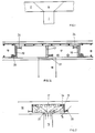
- FIG. 1 shows a support 1 with a concrete ceiling 2, in which construction no special measures for transferring forces from the concrete ceiling 2 into the support 1 are provided, that is to say in particular also no support head.
- the well-known eruption 4 then occurs, which can cause the ceiling to collapse.
- FIGS. 2 and 3 shows a support 16 with a frame, which serves as an edge support 19 and is made of flat steel, glass fiber reinforced plastic or the like. Furthermore, outer and inner composite means 20 and 24 are arranged in a hedgehog-like manner projecting outwards and inwards from the edge carrier 19.
- the force is transferred from the inwardly projecting composite means 24 to the support 16 via a concrete pressure strut 27.
- Any moments as well as forces not taken over by concrete pressure struts can be transferred from beams using a cross 17.
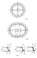
- the shapes are square, rectangular, polygonal, circular, oval or other shapes are provided.
- Fig. 13 shows sections, among others. 2 and 4, in different versions.
- Edge supports 19 and 28 with or without additional supports 17 arranged in a cross or laid in the diagonals can be used as main structures.
- Shapes can be used for these flat or wide flat sheets, double-T or T-rolled profiles or other types of composite profiles and composite structures made of appropriate materials.
- the edge beams 19, 28, shown here as flat bars or Z-profiles, can also be designed as L-profiles, as box profiles or in any composition or as composite structures.
- the edge girder 19 with the composite means 20 is concreted in a concrete ceiling 18, as is analogous, for example, with reference to FIG. 2 and 3 is explained.
- the ceiling 18 is reinforced by means of reinforcing steels 30. From the illustration it can be seen how the U-shaped reinforcing steel is connected to the edge support 19 via the composite means 20.
- Flat or wide flat sheet metal is normally used for the head plates.
- Their shape can be square, rectangular, circular or star-shaped. But it is also possible without constructing these head plates and dimensioning the crosses accordingly.
- the devices according to the invention allow hori zonal and vertical recesses in the ceiling. They are particularly suitable for medium to large loads, but are material and therefore cost-saving for them. They form complete units with a relatively small installation weight and are inexpensive in every respect. They also comply with the SIA 160, 162 standard.
- the inner connection means 24 must be closer to the upper end plane of the ceiling, which is normal to the support, than the outer connection means 20, so that the pressure forces introduced into the pressure strut form a minimum inclination angle ⁇ with this end plane, which is greater than 25 according to SIA standards ° should be. If this angle becomes too small, several frames with composite materials must be provided to ensure that the forces are applied at an angle> 25 ° to the support.
- the new construction explained in detail offers the greatest possible degree of safety and improves the bending strength in the contact area. In addition, it enables perfect reinforcement management and thus optimal force transmission.
Abstract
Description
Die vorliegende Erfindung betrifft eine Verbindungsvorrichtung zum Anschliesen einer Betondecke an eine Stütze sowie ein Bauwerk mit mindestens einer Vorrichtung.The present invention relates to a connecting device for connecting a concrete ceiling to a support and a structure with at least one device.
Es ist bekannt, dass beim Abstützen von Betondecken auf Stützen, wenn nicht besondere Massnahmen getroffen werden, ein sog. Stanzeffekt auftritt, wobei die Stütze als Stempel auf die Betondecke wirkt und einen sich in der Decke normalerweise erweiternden Teil wegen übermässiger Spannungen ausstanzt.It is known that when concrete ceilings are supported on supports, unless special measures are taken, a so-called punching effect occurs, the support acting as a stamp on the concrete ceiling and punching out a part that normally widens in the ceiling due to excessive tension.
Es sind seit langem entsprechende Vorkehrungen getroffen worden, um Kräftespitzen beim Ueberleiten der Kräfte aus der Betondecke in die Stütze durch entsprechende Vorkehrungen so zu führen, dass derartige Stanzerscheinungen ausbleiben.Appropriate measures have long been taken to take force peaks when transferring the forces from the concrete ceiling to the column by taking appropriate measures so that there are no punching phenomena.
In diesem Sinne ist ein Stützenkopf zum Anschluss einer Betonmassivdecke an eine Stahlprofilstütze mit einem vertikalen Durchlass für Versorgerleitungen bekannt geworden, bei welcher Konstruktion der Kopfteil der Stahlprofilstütze mit vertikalen, flügelartigen Stahlblechen versehen wird. Dabei ist ein Verankerungsteil vorgesehen, der aus Reihen von Kopfbolzendübeln besteht, die an den flügelartigen Stahlblechen der Stahlprofilstütze angeschweisst sind. Dieser Stützenkopf vermeidet Spitzenbelastungen, was insbesondere aufgrund des Verankerungsteils, der aus Kopf bolzendübeln besteht, erreicht wird. (DE-OS 29 20 044) Dieser Stützenkopf ist nur für Stahlprofilstützen verwendbar, der offenbarte Grundgedanke ist mithin nicht für reine eisenarmierte Betonbauwerke zu verwenden. Auch dienen die verwendeten Kopfbolzendübel ausschliesslich zum Auflegen und nicht zum mechanischen Verbinden mit Betonbewehrungseisen.In this sense, a column head for connecting a solid concrete ceiling to a steel profile column with a vertical passage for utility lines has become known, in which construction the head part of the steel profile column is provided with vertical, wing-like steel sheets. In this case, an anchoring part is provided, which consists of rows of headed dowels which are welded to the wing-like steel sheets of the steel profile support. This prop head avoids peak loads, which is particularly due to the anchoring part that is made up of head there is bolting, is achieved. (DE-OS 29 20 044) This column head can only be used for steel profile columns, the basic idea disclosed is therefore not to be used for pure iron-reinforced concrete structures. The headed dowels used are only used for laying on and not for mechanical connection with concrete reinforcing bars.
Es ist ferner eine Stahlbetondecke mit wenigstens einer vertikalen Stütze bekannt geworden, bei welcher die Verbindung von Decke und Stütze oder Stützen an der bzw. an jeder Verbindungsstelle durch ein aus Stahlprofil gebildetes, mindestens zweiwinklig zueinander stehende Schenkel aufweisendes, horizontal angeordnetes Element gebildet ist. Die freien Schenkel dieses Elementes sind durch wenigstens ein Stahlglied miteinander verbunden. Zwischen den Schenkeln des horizontalen Elementes und dem zugehörigen Stahlverbindungsglied besteht betonfreier Raum zur Durchführung von Leitungen. (CH-PS 430 128)Furthermore, a reinforced concrete ceiling with at least one vertical support has become known, in which the connection of the ceiling and the support or supports at or at each connection point is formed by a horizontally arranged element made of steel profile and having at least two angles to one another. The free legs of this element are connected to one another by at least one steel link. Concrete-free space for the passage of lines exists between the legs of the horizontal element and the associated steel connecting link. (CH-PS 430 128)
Zum Stande der Technik gehört ferner ein metallischer Säulenknauf, welcher als Verbindungselement zwischen einer stützenden Säule, auf welcher er befestigt ist und einer armierten Betonplatte dient, in welcher Platte er eingegossen ist. Dieser Säulenknauf besteht aus mehreren Stäben, welche miteinander verschweisst sind und welche ein Polygon umschreiben, wobei die von diesem Polygon abstehenden Enden der Stäbe freitragend sind. Diese Stäbe oder Profile sind mit, gegen das Innere des Polygons weisenden, Stiften versehen, welche der Verankerung im Beton dienen.The prior art also includes a metallic column knob, which serves as a connecting element between a supporting column, on which it is fastened, and an armored concrete slab, in which slab it is cast. This column knob consists of several rods, which are welded together and which circumscribe a polygon, the ends of the rods protruding from this polygon being self-supporting. These bars or profiles are provided with pins pointing towards the inside of the polygon, which are used for anchoring in the concrete.
Auch diese Konstruktion vermag den heutigen Anforderungen nicht mehr gerecht zu werden. (CH-A- 596 399)This construction is also no longer able to meet today's requirements. (CH-A-596 399)
Es gehört ferner ein Bauwerk zum Stande der Technik, bei welchem ein Pilz eine mittlere Oeffnung zum Einschieben einer Stütze von oben her besitzt. Dabei wird die in der mittleren Oeffnung befindliche Platte nachträglich mit dem Pilz verbunden, z.B. verschweisst.A building is also part of the prior art, in which a mushroom has a central opening for inserting a support from above. The plate in the middle opening is subsequently connected to the mushroom, e.g. welded.
Diese Veröffentlichung stellt den Stand der Technik dar und zeigt den Nachteil bisheriger Konstruktionen, indem nämlich die Verbindung zwischen Pilz und weiteren Armierungselementen z.T. durch Schweissung erfolgt. Dieses Verfahren ist aufwendig und daher kostspielig. Es verlangt besondere Massnahmen am Ort der Erstellung der Baute. (EP-A- 128 494)This publication represents the state of the art and shows the disadvantage of previous designs, namely that the connection between the mushroom and other reinforcing elements partly. done by welding. This process is complex and therefore expensive. It requires special measures at the place where the building is constructed. (EP-A-128 494)
Die vorliegende Erfindung bezweckt die Schaffung einer Verbindungsvorrichtung, welche gegenüber dem Stand der Technik einen geringen Stahlverbrauch aufweist, vorteilhafte Kräfteverhältnisse im Bereich der Abstützung der Decke auf der Stütze schafft und umweltfreundlich ist.The present invention aims to provide a connecting device which, compared to the prior art, has a low steel consumption, creates advantageous force relationships in the area of supporting the ceiling on the support and is environmentally friendly.
Eine derartige Verbindungsvorrichtung ist gekennzeichnet durch den Wortlaut eines der Ansprüche.Such a connecting device is characterized by the wording of one of the claims.
Die Erfindung wird anschliessend beispielsweise anhand einer Zeichnung erläutert.The invention is subsequently explained, for example, using a drawing.
Es zeigen in rein schematischer Darstelllung:
- Fig. 1 einen Ausschnitt aus einer auf einer Stütze gelagerten Betondecke mit angedeutetem Stanzeffekt,
- Fig. 2 einen Ausschnitt aus einer Betondecke mit Stütze mit angedeuteter Abstützungsvorrichtung der Stahlbetondecke mit dem Einbau der Verbindungsvorrichtung gemäss der vorliegenden Erfindung und der Darstellung des Kraftflusses,
- Fig. 3 eine Aufsicht auf die erfindungsgemässe Verbindungsvorrichtung gemäss Fig. 2,
- Fig. 4, die erfindungsgemässe Vorrichtung mit Fig. 4a Walzprofilen als Randträger mit Verbundmitteln,
- Fig. 5, die erfindungsgemässe Vorrichtung bei der Fig. 6 Verwendung mit einer Randstütze,
- Fig. 7 eine Aufsicht analog Fig. 5 auf eine Eckstütze,
- Fig. 8 eine Innenstütze mit Bereich für Durchdringungen,
- Fig. 9 Aufsichten auf Formvarianten von erfindungsbis 12 gemässen Vorrichtungen auf Mittelstützen analog Fig. 3,
- Fig. 13 Ausschnitte mit Querschnittsvarianten der Vorrichtung,
- Fig. 14 einen Ausschnitt aus einer Armierungsführung für eine statisch einwandfreie Verankerung.
- 1 shows a section of a concrete ceiling mounted on a support with an indicated punching effect,
- 2 shows a section of a concrete ceiling with a support with indicated support device of the reinforced concrete ceiling with the installation of the connecting device according to the present invention and the representation of the force flow,
- 3 is a plan view of the connecting device according to the invention shown in FIG. 2,
- 4, the device according to the invention with FIG. 4a rolled profiles as edge supports with composite means,
- 5, the device according to the invention in FIG. 6 use with an edge support,
- 7 is a plan view analogous to FIG. 5 on a corner support,
- 8 is an inner support with area for penetrations,
- 9 top views of shape variants of devices according to the invention up to 12 according to center supports analogous to FIG. 3,
- Fig. 13 sections with cross-sectional variants of the Contraption,
- 14 shows a section of a reinforcement guide for a structurally perfect anchoring.
In Fig. 1 ist eine Stütze 1 ersichtlich, mit einer Betondecke 2, bei welcher Konstruktion keine besonderen Massnahmen zur Kräfteüberleitung von der Betondecke 2 in die Stütze 1 vorgesehen sind, also insbesondere auch kein Stützkopf. Es tritt dann der bekannte Ausbruch 4 auf, welcher die Decke zum Einsturz bringen kann.1 shows a
Die in den Fig. 2 und 3 dargestellte erfindungsgemässe Konstruktion zeigt eine Stütze 16 mit einem Rahmen, der als Randträger 19 dient und aus Flachstahl, glasfaserarmiertem Kunststoff o. dgl. hergestellt ist. Ferner sind äussere und innere Verbundmittel 20 und 24 nach aussen und innen vom Randträger 19 igelartig vorstehend angeordnet.The construction according to the invention shown in FIGS. 2 and 3 shows a
Von den nach innen abstehenden Verbundmitteln 24 wird die Kraft über eine Betondruckstrebe 27 der Stütze 16 übergeben.The force is transferred from the inwardly projecting composite means 24 to the
Allfällige Momente sowie nicht von Betondruckstreben übernommene Kräfte können mittels eines Kreuzes 17 aus Trägern übergeben werden. Eine Druckplatte 21, zentrisch angeordnet, übergibt diese Kräfte an die Stütze 16.Any moments as well as forces not taken over by concrete pressure struts can be transferred from beams using a
In den Fig. 4 und 4a wird die erfindungsgemässe Kon struktion gezeigt mit einer Stütze 16 sowie einem Rahmen 28 aus einem Z-Profil als Randträger. Auch hier können ein Kreuz 17 und eine Druckplatte 21 vorgesehen werden.4 and 4a, the con structure shown with a
Die Fig. 5 bis 12 zeigen verschiedene Variationen und Anwendungen erfindungsgemässer Vorrichtungen beim Stützen von Betondecken. Dabei sind die Formen quadratisch, rechteckig, vieleckig, kreisförmig, oval oder es sind andere Formen vorgesehen.5 to 12 show different variations and applications of devices according to the invention when supporting concrete ceilings. The shapes are square, rectangular, polygonal, circular, oval or other shapes are provided.
Fig. 13 zeigt Ausschnitte u.a. aus den Fig. 2 und 4, in verschiedenen Ausführungsvarianten. Als Hauptgebilde können Randträger 19 und 28 mit oder ohne im Kreuz angeordneten oder in die Diagonalen verlegten Ergänzungsträgern 17 verwendet werden. Als Formen können für diese Flach- bzw. Breitflachbleche, Doppel-T- oder T-Walzprofile oder andere Arten zusammengesetzter Profile und Verbundkonstruktionen aus entsprechenden Materialien Anwendung finden.Fig. 13 shows sections, among others. 2 and 4, in different versions. Edge supports 19 and 28 with or without
Die Randträger 19, 28, hier als Flacheisen oder Z-Profile dargestellt, können aber auch als L-Profile, als Kastenprofile oder in irgendeiner Zusammensetzung bzw. als Verbundkonstruktionen ausgeführt werden.The edge beams 19, 28, shown here as flat bars or Z-profiles, can also be designed as L-profiles, as box profiles or in any composition or as composite structures.
Fig. 14 zeigt einen Ausschnitt aus einer Armierungsführung für eine statisch einwandfreie Verankerung. Auf dem obern Ende der Stütze 16 ist in einer Betondecke 18 der Randträger 19 mit den Verbundmitteln 20 einbetoniert, wie dies analog z.B. anhand der Fig. 2 und 3 erläutert ist. Die Decke 18 ist mittels Armierungsstählen 30 armiert. Aus der Darstellung ist ersichtlich, wie hier der U-förmig gebogene Armierungsstahl über die Verbundmittel 20 mit dem Randträger 19 verbunden ist.14 shows a section of a reinforcement guide for a structurally perfect anchoring. On the upper end of the
Diese Ausführungsart erlaubt eine einwandfreie, übersichtliche Kräfte-Uebertragung von der Decke 18 in die Stütze 16. Dank dieser neuen Konstruktion gehören die leidigen Probleme mit der unteren Armierung, hier in Form des Stahles 30, bezüglich Verankerung, Schnittlängen und Schweissverbindungen endgültig der Vergangenheit an; denn die, z.B. als Bolzen 20 ausgebildeten Verbundmittel werden mit dem Armierungsnetz nicht verschweisst, wobei der Boden der U-förmig gebogenen Stähle 30 vorzugsweise den Rahmen berührt.This type of construction allows a flawless, clear transfer of forces from the
Als Verbundmittel dienen Schweissbolzen, Bügel aus Stahl oder schrauben- bzw. spiralförmig gewundene Stäbe, Walz-Profilabschnitte oder Rohrabschnitte beliebiger Formen und Materialien, insbesondere auch Z-Profilrahmen.Welding studs, steel brackets or helically or spirally wound rods, rolled profile sections or pipe sections of any shape and material, in particular also Z-profile frames, serve as the connecting means.
Für die Kopfplatten wird normalerweise Flach- bzw. Breitflachblech verwendet. Deren Form kann quadratisch, rechteckig, kreisförmig oder sternförmig sein. Es ist aber auch möglich, ohne diese Kopfplatten zu konstruieren und entsprechend die Kreuze zu dimensionieren.Flat or wide flat sheet metal is normally used for the head plates. Their shape can be square, rectangular, circular or star-shaped. But it is also possible without constructing these head plates and dimensioning the crosses accordingly.
Die erfindungsgemässen Vorrichtungen erlauben hori zontale und vertikale Aussparungen in der Decke. Sie eignen sich insbesondere für mittlere bis grosse Lasten, sind aber für diese material- und damit kostensparend. Sie bilden komplette Einheiten mit relativ kleinem Verlegegewicht und sind in jeder Beziehung kostengünstig. Sie entsprechen im übrigen der Norm SIA 160, 162.The devices according to the invention allow hori zonal and vertical recesses in the ceiling. They are particularly suitable for medium to large loads, but are material and therefore cost-saving for them. They form complete units with a relatively small installation weight and are inexpensive in every respect. They also comply with the SIA 160, 162 standard.
Bei diesen, auf einer gemeinsamen Grundidee fussenden Konstruktionen werden die äusseren Kräfte über äussere Verbundmittel auf ein rahmenartiges Gebilde übertragen und von dort auf innere Verbundmittel. Von hier gelangen diese Kräfte als Druckkräfte auf eine Druckstrebe, welche diese Kräfte auf die Stütze weiterleitet.In these constructions, which are based on a common basic idea, the external forces are transferred to a frame-like structure via external composite means and from there to internal composite means. From here, these forces arrive as pressure forces on a pressure strut, which transmits these forces to the support.
Dabei müssen die inneren Verbundmittel 24 näher bei der oberen, normal zur Stütze liegenden Abschlussebene der Decke liegen als die äusseren Verbundmittel 20, damit die in der Druckstrebe eingeführten Druckkräfte mit dieser Abschlussebene einen Mindest-Neigungswinkel ψ bilden, der gemäss SIA-Normen grösser als 25° sein soll. Würde dieser Winkel zu klein, so sind mehrere Rahmen mit Verbundmitteln vorzusehen, um die Zuführung der Kräfte unter einem Winkel > 25° zur Stütze sicherzustellen.The inner connection means 24 must be closer to the upper end plane of the ceiling, which is normal to the support, than the outer connection means 20, so that the pressure forces introduced into the pressure strut form a minimum inclination angle ψ with this end plane, which is greater than 25 according to SIA standards ° should be. If this angle becomes too small, several frames with composite materials must be provided to ensure that the forces are applied at an angle> 25 ° to the support.
Die in Einzelheiten erläuterte neue Konstruktion bietet ein grösstmögliches Mass an Sicherheit und verbessert die Biegefestigkeit im Auflagebereich. Zudem ermöglicht sie eine einwandfreie Bewehrungsfuhrung und dadurch eine optimale Krafteinleitung.The new construction explained in detail offers the greatest possible degree of safety and improves the bending strength in the contact area. In addition, it enables perfect reinforcement management and thus optimal force transmission.
Sie ist damit insbesondere hervorragend zur Aufnahme von hohen Durchstanzlasten geeignet.It is therefore particularly well suited for absorbing high punching loads.
Dabei ist mithin vorteilhafterweise
- a) keine Schubarmierung notwendig, da τ eff. < als τ zul.
- b) alles vollständig einbetoniert. Es gibt keine vorstehenden Teile.
- c) eine einfache Bewehrungsführung sichergestellt, da alle Verbundmittel, z.B. die
Bolzen 20, in einer Ebene liegen.
- a) no shear reinforcement necessary, since τ eff. <as τ allow.
- b) everything completely concreted. There are no protruding parts.
- c) simple reinforcement routing ensured, since all the composite means, for example the
bolts 20, lie in one plane.
Diese Verbindungselemente werden als "Igel" bezeichnet, insbesondere als Riss-Igel.These connecting elements are referred to as "hedgehogs", in particular as torn hedgehogs.
Es kann, insbesondere bei Aussparungen innerhalb der Randträger, nötig werden, diesen durch z.B. kreuzartige mittige Träger zu verstärken.It may be necessary, especially in the case of recesses within the edge girders, e.g. reinforce cruciform central straps.
Alle in der Beschreibung und/oder den Figuren dargestellten Einzelteile und Einzelmerkmale sowie deren Permutationen, Kombinationen und Variationen sind erfinderisch, und zwar für n Einzelteile und Einzelmerkmale mit den Werten n = 1 bis n →∞.All of the individual parts and individual features shown in the description and / or the figures and their permutations, combinations and variations are inventive, namely for n individual parts and individual features with the values n = 1 to n → ∞.
Claims (9)
Priority Applications (1)
| Application Number | Priority Date | Filing Date | Title |
|---|---|---|---|
| AT88118231T ATE72001T1 (en) | 1987-11-30 | 1988-11-02 | CONNECTING DEVICE FOR CONNECTING A CONCRETE COVER TO A SUPPORT AND STRUCTURE. |
Applications Claiming Priority (2)
| Application Number | Priority Date | Filing Date | Title |
|---|---|---|---|
| CH4653/87 | 1987-11-30 | ||
| CH465387 | 1987-11-30 |
Publications (2)
| Publication Number | Publication Date |
|---|---|
| EP0318712A1 true EP0318712A1 (en) | 1989-06-07 |
| EP0318712B1 EP0318712B1 (en) | 1992-01-22 |
Family
ID=4280128
Family Applications (1)
| Application Number | Title | Priority Date | Filing Date |
|---|---|---|---|
| EP88118231A Expired - Lifetime EP0318712B1 (en) | 1987-11-30 | 1988-11-02 | Connection device for coupling between a concrete floor and a column, and building |
Country Status (4)
| Country | Link |
|---|---|
| EP (1) | EP0318712B1 (en) |
| AT (1) | ATE72001T1 (en) |
| DE (1) | DE3868025D1 (en) |
| NO (1) | NO884885D0 (en) |
Cited By (9)
| Publication number | Priority date | Publication date | Assignee | Title |
|---|---|---|---|---|
| GB2235221A (en) * | 1989-08-21 | 1991-02-27 | Square Grip Ltd | Shearhead |
| EP0557731A1 (en) * | 1992-01-28 | 1993-09-01 | Fundia Betoniteräkset Oy Ab | Reinforcement for a concrete slab |
| WO1995028534A1 (en) * | 1994-04-13 | 1995-10-26 | Zellner, Wilhelm | Dowel strip for bent-up bars |
| WO1997036067A1 (en) * | 1996-03-26 | 1997-10-02 | Sicon S.R.O. | Joint of concrete building elements |
| EP1180565A1 (en) | 2000-08-08 | 2002-02-20 | Philippe Menetrey | Flexible connecting reinforcement for the reinforcement of concrete structures |
| DE19741509B4 (en) * | 1997-09-20 | 2004-03-11 | Stahl + Verbundbau Gesellschaft für industrielles Bauen m.b.H. | Column head extension as punching shear reinforcement in reinforced concrete slabs |
| DE102004005916A1 (en) * | 2004-02-06 | 2005-09-01 | Tue, Nguyen Viet, Prof. Dr.-Ing.habil. | Mounting part e.g. for concrete for increasing load under pressure, has special fitting for concrete to be applied with tubular pipe arranged between load introduction surfaces |
| AT503475B1 (en) * | 2006-03-23 | 2009-01-15 | Katzenberger Baustoffindustrie | FLAT CEILING OF REINFORCED LAYER BEETON AND / OR CONCRETE REPAIR ELEMENTS |
| US20110094182A1 (en) * | 2008-05-19 | 2011-04-28 | Jeom Han KIM | Stiffener for connecting prestressed concrete beam and method of constructing structure using the same |
Citations (7)
| Publication number | Priority date | Publication date | Assignee | Title |
|---|---|---|---|---|
| CH382950A (en) * | 1964-04-23 | 1964-10-15 | Geilinger & Co | Support device for a reinforced concrete ceiling |
| CH430128A (en) * | 1965-10-19 | 1967-02-15 | Geilinger & Co | Reinforced concrete ceiling |
| DE2108524A1 (en) * | 1971-02-23 | 1973-05-10 | Bodo Rasch | SYSTEM FOR FRAMEWORK CONSTRUCTIONS - CONSISTS OF ELEMENTS IN MUSHROOM CONSTRUCTION - INDUSTRIAL MANUFACTURED AND ASSEMBLED ON THE SITE SUITABLE FOR ONE-STOREY AND MULTI-STOREY BUILDINGS - OR FOR MULTI-STOREY AND MIDDLE-STOREY HOUSEHOLD |
| CH596399A5 (en) * | 1975-09-12 | 1978-03-15 | Zwahlen & Mayr Sa | Metal cap to connect column and concrete slab |
| DE2920044A1 (en) * | 1979-05-18 | 1980-11-27 | Spannverbund Ges Fuer Verbundt | Steel column head for solid concrete ceiling joint - has head bolt dowels anchoring wing plates passing through vertical duct hole |
| EP0128994A1 (en) * | 1983-10-06 | 1984-12-27 | Geilinger AG | Method of manufacturing a building |
| EP0163923A1 (en) * | 1984-05-10 | 1985-12-11 | Wolfhart Dr.-Ing. Andrä | Connection between a cast-in-situ slab and precast columns |
-
1988
- 1988-11-02 EP EP88118231A patent/EP0318712B1/en not_active Expired - Lifetime
- 1988-11-02 DE DE8888118231T patent/DE3868025D1/en not_active Expired - Fee Related
- 1988-11-02 AT AT88118231T patent/ATE72001T1/en not_active IP Right Cessation
- 1988-11-02 NO NO884885A patent/NO884885D0/en unknown
Patent Citations (7)
| Publication number | Priority date | Publication date | Assignee | Title |
|---|---|---|---|---|
| CH382950A (en) * | 1964-04-23 | 1964-10-15 | Geilinger & Co | Support device for a reinforced concrete ceiling |
| CH430128A (en) * | 1965-10-19 | 1967-02-15 | Geilinger & Co | Reinforced concrete ceiling |
| DE2108524A1 (en) * | 1971-02-23 | 1973-05-10 | Bodo Rasch | SYSTEM FOR FRAMEWORK CONSTRUCTIONS - CONSISTS OF ELEMENTS IN MUSHROOM CONSTRUCTION - INDUSTRIAL MANUFACTURED AND ASSEMBLED ON THE SITE SUITABLE FOR ONE-STOREY AND MULTI-STOREY BUILDINGS - OR FOR MULTI-STOREY AND MIDDLE-STOREY HOUSEHOLD |
| CH596399A5 (en) * | 1975-09-12 | 1978-03-15 | Zwahlen & Mayr Sa | Metal cap to connect column and concrete slab |
| DE2920044A1 (en) * | 1979-05-18 | 1980-11-27 | Spannverbund Ges Fuer Verbundt | Steel column head for solid concrete ceiling joint - has head bolt dowels anchoring wing plates passing through vertical duct hole |
| EP0128994A1 (en) * | 1983-10-06 | 1984-12-27 | Geilinger AG | Method of manufacturing a building |
| EP0163923A1 (en) * | 1984-05-10 | 1985-12-11 | Wolfhart Dr.-Ing. Andrä | Connection between a cast-in-situ slab and precast columns |
Cited By (13)
| Publication number | Priority date | Publication date | Assignee | Title |
|---|---|---|---|---|
| GB2235221B (en) * | 1989-08-21 | 1993-08-25 | Square Grip Ltd | Shearhead reinforcement |
| GB2235221A (en) * | 1989-08-21 | 1991-02-27 | Square Grip Ltd | Shearhead |
| EP0557731A1 (en) * | 1992-01-28 | 1993-09-01 | Fundia Betoniteräkset Oy Ab | Reinforcement for a concrete slab |
| US5867960A (en) * | 1994-04-13 | 1999-02-09 | Andrae; Hans-Peter | Dowel member for reinforcing concrete structures |
| WO1995028534A1 (en) * | 1994-04-13 | 1995-10-26 | Zellner, Wilhelm | Dowel strip for bent-up bars |
| US6058669A (en) * | 1996-03-26 | 2000-05-09 | Sicon, S.R.O. | Joint of concrete building elements |
| WO1997036067A1 (en) * | 1996-03-26 | 1997-10-02 | Sicon S.R.O. | Joint of concrete building elements |
| DE19741509B4 (en) * | 1997-09-20 | 2004-03-11 | Stahl + Verbundbau Gesellschaft für industrielles Bauen m.b.H. | Column head extension as punching shear reinforcement in reinforced concrete slabs |
| EP1180565A1 (en) | 2000-08-08 | 2002-02-20 | Philippe Menetrey | Flexible connecting reinforcement for the reinforcement of concrete structures |
| DE102004005916A1 (en) * | 2004-02-06 | 2005-09-01 | Tue, Nguyen Viet, Prof. Dr.-Ing.habil. | Mounting part e.g. for concrete for increasing load under pressure, has special fitting for concrete to be applied with tubular pipe arranged between load introduction surfaces |
| AT503475B1 (en) * | 2006-03-23 | 2009-01-15 | Katzenberger Baustoffindustrie | FLAT CEILING OF REINFORCED LAYER BEETON AND / OR CONCRETE REPAIR ELEMENTS |
| US20110094182A1 (en) * | 2008-05-19 | 2011-04-28 | Jeom Han KIM | Stiffener for connecting prestressed concrete beam and method of constructing structure using the same |
| US8166717B2 (en) * | 2008-05-19 | 2012-05-01 | Cross Structural Consultant Co., Ltd. | Stiffener for connecting prestressed concrete beam and method of constructing structure using the same |
Also Published As
| Publication number | Publication date |
|---|---|
| DE3868025D1 (en) | 1992-03-05 |
| ATE72001T1 (en) | 1992-02-15 |
| NO884885D0 (en) | 1988-11-02 |
| EP0318712B1 (en) | 1992-01-22 |
Similar Documents
| Publication | Publication Date | Title |
|---|---|---|
| DE1903129C3 (en) | Device for connecting a beam to a concrete column | |
| DE2716388A1 (en) | JOINING PANELS | |
| DE1609310A1 (en) | Vault construction and procedures for their construction | |
| EP0318712B1 (en) | Connection device for coupling between a concrete floor and a column, and building | |
| DE4023465A1 (en) | TOWER CONSTRUCTION | |
| DE1914298A1 (en) | Connection of relatively inclined reinforced concrete beam parts | |
| EP0023042B1 (en) | Prefabricated floor element for buildings | |
| EP1630315A1 (en) | Construction element for shear and punching reinforcement | |
| DE3403140C1 (en) | Structure, in particular bridge structure | |
| DE102017114090B4 (en) | Method of constructing a building | |
| DE3343721A1 (en) | HIGH, DETACHED CHIMNEY OR TOWER MADE OF REINFORCED CONCRETE | |
| CH651095A5 (en) | REINFORCEMENT ELEMENT FOR TRANSMITTING LATERAL FORCES IN PANEL-LIKE SUPPORT LINKS, e.g. FLAT CEILINGS. | |
| DE102018131066A1 (en) | Reinforcement, concrete element, module connection, module block and building | |
| DE2649936A1 (en) | REINFORCED CONCRETE CONTAINER AND METHOD OF ERECTING IT | |
| EP0376167B1 (en) | Mast for a building lift, in particular for a rack lift | |
| EP1860246B1 (en) | Building element for heat insulation | |
| DE4000956C2 (en) | Element for large panel construction made of concrete | |
| DE19636026C1 (en) | Auxiliary frame for goods vehicle, particularly one equipped with crane | |
| DE8027569U1 (en) | PLATE, ESPECIALLY CONCRETE CEILING | |
| DE202005006228U1 (en) | Roof construction for buildings, especially industrial buildings with large widths, comprises bottom and top booms in the form of I-shaped supports with two boom flanges, and node elements with two flat node flange plates | |
| DE2153495A1 (en) | PREFABRICATED CEILING PANEL FOR ASSEMBLY CONSTRUCTION | |
| EP0796961B1 (en) | Foam concrete elements with reinforcing system | |
| DE19903310A1 (en) | Compound support as steel support for bridge structure | |
| DE2438376A1 (en) | Latticed double panel for multiple-service-installation building - with octagonal cutout sides coinciding with base lines of strut-connecting shafts | |
| WO2007036813A2 (en) | Composite column |
Legal Events
| Date | Code | Title | Description |
|---|---|---|---|
| PUAI | Public reference made under article 153(3) epc to a published international application that has entered the european phase |
Free format text: ORIGINAL CODE: 0009012 |
|
| AK | Designated contracting states |
Kind code of ref document: A1 Designated state(s): AT BE CH DE ES FR GB GR IT LI LU NL SE |
|
| 17P | Request for examination filed |
Effective date: 19890717 |
|
| 17Q | First examination report despatched |
Effective date: 19900704 |
|
| GRAA | (expected) grant |
Free format text: ORIGINAL CODE: 0009210 |
|
| AK | Designated contracting states |
Kind code of ref document: B1 Designated state(s): AT BE CH DE ES FR GB GR IT LI LU NL SE |
|
| PG25 | Lapsed in a contracting state [announced via postgrant information from national office to epo] |
Ref country code: IT Free format text: LAPSE BECAUSE OF FAILURE TO SUBMIT A TRANSLATION OF THE DESCRIPTION OR TO PAY THE FEE WITHIN THE PRE;WARNING: LAPSES OF ITALIAN PATENTS WITH EFFECTIVE DATE BEFORE 2007 MAY HAVE OCCURRED AT ANY TIME BEFORE 2007. THE CORRECT EFFECTIVE DATE MAY BE DIFFERENT FROM THE ONE RECORDED.SCRIBED TIME-LIMIT Effective date: 19920122 Ref country code: GB Effective date: 19920122 Ref country code: SE Effective date: 19920122 Ref country code: BE Effective date: 19920122 Ref country code: NL Effective date: 19920122 Ref country code: ES Free format text: THE PATENT HAS BEEN ANNULLED BY A DECISION OF A NATIONAL AUTHORITY Effective date: 19920122 Ref country code: GR Free format text: LAPSE BECAUSE OF FAILURE TO SUBMIT A TRANSLATION OF THE DESCRIPTION OR TO PAY THE FEE WITHIN THE PRESCRIBED TIME-LIMIT Effective date: 19920122 |
|
| REF | Corresponds to: |
Ref document number: 72001 Country of ref document: AT Date of ref document: 19920215 Kind code of ref document: T |
|
| REF | Corresponds to: |
Ref document number: 3868025 Country of ref document: DE Date of ref document: 19920305 |
|
| ET | Fr: translation filed | ||
| NLV1 | Nl: lapsed or annulled due to failure to fulfill the requirements of art. 29p and 29m of the patents act | ||
| GBV | Gb: ep patent (uk) treated as always having been void in accordance with gb section 77(7)/1977 [no translation filed] | ||
| PG25 | Lapsed in a contracting state [announced via postgrant information from national office to epo] |
Ref country code: AT Effective date: 19921102 |
|
| PGFP | Annual fee paid to national office [announced via postgrant information from national office to epo] |
Ref country code: DE Payment date: 19921123 Year of fee payment: 5 |
|
| PGFP | Annual fee paid to national office [announced via postgrant information from national office to epo] |
Ref country code: FR Payment date: 19921125 Year of fee payment: 5 |
|
| PLBE | No opposition filed within time limit |
Free format text: ORIGINAL CODE: 0009261 |
|
| STAA | Information on the status of an ep patent application or granted ep patent |
Free format text: STATUS: NO OPPOSITION FILED WITHIN TIME LIMIT |
|
| PG25 | Lapsed in a contracting state [announced via postgrant information from national office to epo] |
Ref country code: LU Free format text: LAPSE BECAUSE OF NON-PAYMENT OF DUE FEES Effective date: 19921130 |
|
| 26N | No opposition filed | ||
| PGFP | Annual fee paid to national office [announced via postgrant information from national office to epo] |
Ref country code: CH Payment date: 19930129 Year of fee payment: 5 |
|
| PG25 | Lapsed in a contracting state [announced via postgrant information from national office to epo] |
Ref country code: LI Effective date: 19931130 Ref country code: CH Effective date: 19931130 |
|
| PG25 | Lapsed in a contracting state [announced via postgrant information from national office to epo] |
Ref country code: FR Effective date: 19940729 |
|
| REG | Reference to a national code |
Ref country code: CH Ref legal event code: PL |
|
| PG25 | Lapsed in a contracting state [announced via postgrant information from national office to epo] |
Ref country code: DE Effective date: 19940802 |
|
| REG | Reference to a national code |
Ref country code: FR Ref legal event code: ST |