EP0318074B2 - Device for cleaning runways - Google Patents
Device for cleaning runways Download PDFInfo
- Publication number
- EP0318074B2 EP0318074B2 EP88202385A EP88202385A EP0318074B2 EP 0318074 B2 EP0318074 B2 EP 0318074B2 EP 88202385 A EP88202385 A EP 88202385A EP 88202385 A EP88202385 A EP 88202385A EP 0318074 B2 EP0318074 B2 EP 0318074B2
- Authority
- EP
- European Patent Office
- Prior art keywords
- filter
- water
- bag
- nozzles
- cyclone
- Prior art date
- Legal status (The legal status is an assumption and is not a legal conclusion. Google has not performed a legal analysis and makes no representation as to the accuracy of the status listed.)
- Expired - Lifetime
Links
Images

Classifications
-
- E—FIXED CONSTRUCTIONS
- E01—CONSTRUCTION OF ROADS, RAILWAYS, OR BRIDGES
- E01H—STREET CLEANING; CLEANING OF PERMANENT WAYS; CLEANING BEACHES; DISPERSING OR PREVENTING FOG IN GENERAL CLEANING STREET OR RAILWAY FURNITURE OR TUNNEL WALLS
- E01H1/00—Removing undesirable matter from roads or like surfaces, with or without moistening of the surface
- E01H1/10—Hydraulically loosening or dislodging undesirable matter; Raking or scraping apparatus ; Removing liquids or semi-liquids e.g., absorbing water, sliding-off mud
- E01H1/101—Hydraulic loosening or dislodging, combined or not with mechanical loosening or dislodging, e.g. road washing machines with brushes or wipers
- E01H1/103—Hydraulic loosening or dislodging, combined or not with mechanical loosening or dislodging, e.g. road washing machines with brushes or wipers in which the soiled loosening or washing liquid is removed, e.g. by suction
Definitions
- the invention relates to a device for cleaning a flat surface with powerful water jets, in particular for removing rubber from runways, comprising one or more nozzles which are connected by means of a pipe to a source of pressurized water, a circulation system which is movable with the nozzles, said system being at least provided with a water tank, a pump unit connected thereto for raising the water to high pressure, a hood with suction line fitted around the nozzles, filter means for removing solids from the water extracted from the hood said filter means including filter means for coarse particles and filter means for small particles, a return pipe to the tank and a cyclone.
- Such a device is known from DE-A-3538539.
- Another known method is to remove the rubber deposit using powerful water jets which are directed at the runway from nozzles at a distance of about 60 cm.
- the pressure used is, for example, about 400 bars and water consumption is 70 to 100 litres of water per minute.
- the water polluted with rubber particles goes into the environment, so that this method also is harmful to the environment.
- Other disadvantages are that water consumption is high and control is so imperfect that there is a great risk of the asphalt surface being damaged.
- the device disclosed in DE-A-3538539 comprises flotation means for removing small particles.
- These flotation means include a collecting tank for pre-cleaned liquid, two flotation tanks, a bag-type filter for receiving stripped-off skim and a tank for taking up rest water.
- the five tanks are space consuming and heavy. Further very small particles cannot be removed efficiently.
- the vehicle on which the device is mounted is very heavy and big and a lot of liquid must be present.
- the aim of the invention is to provide a cleaning device according to the preamble which is relatively light and small, which works with a small water volume, which has a small water consumption, which prevents filter clogging by coarse rubber lumps and which enables the user to clean the filter for removing very small particles by flushing.
- a very high water pressure is used which means a pressure of the order of 1,800 to 2,400 bars.
- Less than 25 litres per minute is sprayed onto the runway.
- the re-circulation means that the rubber passes into filters and quite a considerable quantity of the water sprayed onto the runway is returned to the tank.
- the water consumption is therefore only about one quarter of the water consumption with the water jet method without re-circulation. Since most of the water is removed from the runway, the latter is always available for emergency landings.
- the tank can be made relatively small and can be carried on a vehicle with the nozzles.
- the brochure "Das Atümat-System für die Kanalgraphy" of the firm Woma Apparatebau Wolfgang Maasberg & Co, GmbH, 4100 Duisberg 14 in Germany discloses a device for cleaning a sewer with powerful water jets, comprising a number of nozzles connected by a high pressure hose to a source of pressurized water, a suction hose, a circulating system provided with a water tank, a pump unit for raising the water to high pressure, and filter means for removing solids from the water including a first filter step being a pushing plate for pushing the solids together, a second filter step being a screening chamber, a third filter step being a suction filter, a fourth filter step being a cyclone filter and a fifth filter step being a fine filter.
- This known device is not suitable for removing rubber from runways since the big rubber pieces would lead to clogging of the filter system.
- the bag-type filters for removing parts bigger than 3 ⁇ m are located downstream of the cyclone and the activated carbon filter is located downstream of the bag-type filters.
- the bag-type filters have to be replaced periodically, and in order to do this without interrupting the working of the device, two or more bag-type filters are disposed in parallel and valves are present in the pipes to the bag-type filters.
- the high-pressure pump is designed as an intensifier provided with a hydraulically driven plunger system which converts relatively low pressure and high delivery into very high pressure and low delivery into very
- a high suction output as regards the water in the nozzle hood is achieved if the suction hose opens out tangentially into the hood fitted around the nozzles.
- a number of nozzles will be disposed on a rotary vertical shaft.
- the high-pressure pump (intensifier) must be protected from solids being washed out of the tank.
- a duplex filter is therefore provided in the connection between the water tank and high-pressure pump.
- Fig. 1 shows a schematic view of the device according to the invention.
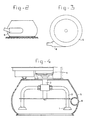
- Figs. 2, 3 and 4 show a side view, a top view and a cross section respectively of the hood in which the jet nozzles are disposed.
- the device shown is intended for cleaning flat surfaces. Its particular object is to remove rubber deposits caused by aircraft tyres on airport runways. Use is made of powerful water jets which are directed towards the ground at a distance of about 15 cm from the ground.
- the two nozzles are indicated by 1 in Fig. 4. They are each disposed on the end of a pipe 2 which is connectecd to a central hollow shaft 3, which can be rotated by means of a drive mechanism 4.
- the nozzles are located in a round hood 5 into which a suction line 6 opens tangentially.
- Fig. 1 shows schematically the whole device with the pressure generator, filters and recirculation systems. This device is placed on a vehicle which can also carry the hood 5 with nozzles.
- the filter and recirculation system can be placed on a separate vehicle which follows the vehicle 7 on which the hood 5 is mounted.
- the suction line 6 of the hood 5 is connected to a suction hose 8 which leads to a cyclone 9.
- Compressed air produced by a compressor 13 can be conveyed through line 14 to the cabinet 10 opposite the venturi fittings 12, vacuum being created in the top part of the cyclone.
- the purpose of this vacuum is to carry the soiled water through the hose 8 to the cyclone and in conjunction with the functioning of the cyclone to separate off the soiled water.
- a diaphragm pump 16 is connected by means of a line 17 to the discharge side and by means of a line 18 to the inlet side of the filter 15.
- a ball valve 19, 20 is provided in each of the lines 17, 18.
- the diaphragm pump 16 is connected to bag-type filters 22 and 23 by means of line 21 and two branches 21a and 21b.
- a valve 24a, 24b is fitted in each of the branches.
- the soiled water coming from the cyclone is pumped by the pump 16 to one of the bag-type filters 22, 23, in which particles larger than 3 ⁇ m are recovered.
- a line 25 connects the discharge side of the bag-type filters to a diaphragm pump 26, which is connected by means of line 27 to a sand activated carbon filter 28.
- the discharge side of said filter is connected by means of a line 29 to a water tank 30.
- the fine particles are removed in the filter 28 from the water from which the coarse material has been removed, and the cleansed water flows back into the tank 30.
- water flows through pipe 31 to a hydraulically driven variable displacement pump 32 (intensifier) for the generation of ultra-high pressure (for example, 2,200 bars), while a duplex filter 33 is placed in the line 31.
- a hydraulically driven variable displacement pump 32 intensifier
- ultra-high pressure for example, 2,200 bars
- a duplex filter 33 is placed in the line 31.
- the quantity of water sprayed on the asphalt is about 24.5 litres per minute. Since the water sprayed onto the runway is removed, the runway is always available for emergency landings.
- the recycling ensures that the tank 30 can be relatively small, and is thus transportable on a vehicle.
- the sand activated carbon filter has to be flushed clean from time to time.
- provision is made between the tank 30 and a branch point of the line 25 for a line 35, in which a valve 36 is placed.
- the flushing system also needs a valve 37 in the line 25, a valve 38 in the line 27, a line 39 connecting the lines 27 and 29 to valve 40, and a line 41 connecting lines 27 and 21 to valve 42, and a valve 43 in the line 29.
- the filter 28 can be flushed back, water being conveyed to a bag-type filter 22 or 23.
- valves 24a, 24b In normal operation one of the bag-type filters is always in use. Through operation of the valves 24a, 24b, it is possible to switch over from one bag-type filter to the other, and the used filter can be replaced without the work having to be interrupted.
Abstract
Description
- The invention relates to a device for cleaning a flat surface with powerful water jets, in particular for removing rubber from runways, comprising one or more nozzles which are connected by means of a pipe to a source of pressurized water, a circulation system which is movable with the nozzles, said system being at least provided with a water tank, a pump unit connected thereto for raising the water to high pressure, a hood with suction line fitted around the nozzles, filter means for removing solids from the water extracted from the hood said filter means including filter means for coarse particles and filter means for small particles, a return pipe to the tank and a cyclone.
- Such a device is known from DE-A-3538539.
- It is known that tyre marks on airport runways can form an impenetrable layer which prevents water from draining away when there is heavy rain. There is then a risk of aircraft aquaplaning on landing or take-off. Various methods of removing the rubber layer are known. Using chemicals to dissolve the rubber and water jets to flush the runway clean has the disadvantages that the tyres of aircraft travelling on the runway run the risk of being attacked and the environment is adversely affected. Besides, this method is timeconsuming. The runway in question has to be shut down for two days.
- Another known method is to remove the rubber deposit using powerful water jets which are directed at the runway from nozzles at a distance of about 60 cm. The pressure used is, for example, about 400 bars and water consumption is 70 to 100 litres of water per minute. The water polluted with rubber particles goes into the environment, so that this method also is harmful to the environment. Other disadvantages are that water consumption is high and control is so imperfect that there is a great risk of the asphalt surface being damaged.
- The device disclosed in DE-A-3538539 comprises flotation means for removing small particles. These flotation means include a collecting tank for pre-cleaned liquid, two flotation tanks, a bag-type filter for receiving stripped-off skim and a tank for taking up rest water. The five tanks are space consuming and heavy. Further very small particles cannot be removed efficiently. The vehicle on which the device is mounted is very heavy and big and a lot of liquid must be present.
- The aim of the invention is to provide a cleaning device according to the preamble which is relatively light and small, which works with a small water volume, which has a small water consumption, which prevents filter clogging by coarse rubber lumps and which enables the user to clean the filter for removing very small particles by flushing.
- Preferably a very high water pressure is used which means a pressure of the order of 1,800 to 2,400 bars. Less than 25 litres per minute is sprayed onto the runway. The re-circulation means that the rubber passes into filters and quite a considerable quantity of the water sprayed onto the runway is returned to the tank. The water consumption is therefore only about one quarter of the water consumption with the water jet method without re-circulation. Since most of the water is removed from the runway, the latter is always available for emergency landings. The tank can be made relatively small and can be carried on a vehicle with the nozzles.
- The brochure "Das Atümat-System für die Kanalreinigung" of the firm Woma Apparatebau Wolfgang Maasberg & Co, GmbH, 4100 Duisberg 14 in Germany discloses a device for cleaning a sewer with powerful water jets, comprising a number of nozzles connected by a high pressure hose to a source of pressurized water, a suction hose, a circulating system provided with a water tank, a pump unit for raising the water to high pressure, and filter means for removing solids from the water including a first filter step being a pushing plate for pushing the solids together, a second filter step being a screening chamber, a third filter step being a suction filter, a fourth filter step being a cyclone filter and a fifth filter step being a fine filter.
- This known device is not suitable for removing rubber from runways since the big rubber pieces would lead to clogging of the filter system.
- Among others it is essential for the present invention that in the first filter step air is removed by a cyclone and the coarse lumps are filtered out at the bottom of the cyclone. Further it is of importance that the bag-type filters for removing parts bigger than 3 µm are located downstream of the cyclone and the activated carbon filter is located downstream of the bag-type filters.
- The bag-type filters have to be replaced periodically, and in order to do this without interrupting the working of the device, two or more bag-type filters are disposed in parallel and valves are present in the pipes to the bag-type filters.
- In order to achieve the very high water pressure (about 2,200 bars) which is necessary for the process, the high-pressure pump is designed as an intensifier provided with a hydraulically driven plunger system which converts relatively low pressure and high delivery into very high pressure and low delivery into very
- A high suction output as regards the water in the nozzle hood is achieved if the suction hose opens out tangentially into the hood fitted around the nozzles.
- Normally, a number of nozzles will be disposed on a rotary vertical shaft.
- The high-pressure pump (intensifier) must be protected from solids being washed out of the tank. A duplex filter is therefore provided in the connection between the water tank and high-pressure pump.
- The invention will now be explained in greater detail with reference to the figures, in which an embodiment is shown.
- Fig. 1 shows a schematic view of the device according to the invention.
- Figs. 2, 3 and 4 show a side view, a top view and a cross section respectively of the hood in which the jet nozzles are disposed.
- The device shown is intended for cleaning flat surfaces. Its particular object is to remove rubber deposits caused by aircraft tyres on airport runways. Use is made of powerful water jets which are directed towards the ground at a distance of about 15 cm from the ground. The two nozzles are indicated by 1 in Fig. 4. They are each disposed on the end of a
pipe 2 which is connectecd to a centralhollow shaft 3, which can be rotated by means of adrive mechanism 4. The nozzles are located in around hood 5 into which asuction line 6 opens tangentially. - The
hood 5 with nozzles is disposed on a vehicle 7. Fig. 1 shows schematically the whole device with the pressure generator, filters and recirculation systems. This device is placed on a vehicle which can also carry thehood 5 with nozzles. - This is not necessary, in other words the filter and recirculation system can be placed on a separate vehicle which follows the vehicle 7 on which the
hood 5 is mounted. - The
suction line 6 of thehood 5 is connected to asuction hose 8 which leads to a cyclone 9. Provision is made on the cyclone for acabinet 10 which is connected by of abasket 11 to the inside of the cyclone, and to which a number ofventuri fittings 12 are connected. - Compressed air produced by a
compressor 13 can be conveyed throughline 14 to thecabinet 10 opposite theventuri fittings 12, vacuum being created in the top part of the cyclone. The purpose of this vacuum is to carry the soiled water through thehose 8 to the cyclone and in conjunction with the functioning of the cyclone to separate off the soiled water. - On the bottom of the cyclone is a
filter 15 for separating off relatively coarse fragments from the deaerated soiled water. Adiaphragm pump 16 is connected by means of aline 17 to the discharge side and by means of a line 18 to the inlet side of thefilter 15. - A
ball valve 19, 20 is provided in each of thelines 17, 18. - The
diaphragm pump 16 is connected to bag-type filters line 21 and twobranches valve 24a, 24b is fitted in each of the branches. - The soiled water coming from the cyclone is pumped by the
pump 16 to one of the bag-type filters - A line 25 connects the discharge side of the bag-type filters to a
diaphragm pump 26, which is connected by means ofline 27 to a sand activatedcarbon filter 28. The discharge side of said filter is connected by means of aline 29 to awater tank 30. - The fine particles are removed in the
filter 28 from the water from which the coarse material has been removed, and the cleansed water flows back into thetank 30. From this tank water flows throughpipe 31 to a hydraulically driven variable displacement pump 32 (intensifier) for the generation of ultra-high pressure (for example, 2,200 bars), while aduplex filter 33 is placed in theline 31. By means of a plunger system in this pump, oil displacement at relatively low pressure and relatively high delivery is converted into water displacement at relatively high pressure and relatively low delivery. Such an intensifier is known and is marketed, inter alia, under the named JETPAC. The intensifier pump is connected by means of line 34 to thenozzle hood 5. - By means of the re-circulation system in which a substantial part of the water sprayed onto the runway or other surface is recirculated to the
tank 30, daily water consumption can be limited to 4 to 5 m³. With known flushing systems it is 20 to 25 m³. A very considerable part of the rubber removed goes into thefilters - It is extremely important that flushing can be controlled through the ultra-high pressure and the height setting of the
hood 5 above the surface in such a way that there is little or no damage to the asphalt. The quantity of water sprayed on the asphalt is about 24.5 litres per minute. Since the water sprayed onto the runway is removed, the runway is always available for emergency landings. - The recycling ensures that the
tank 30 can be relatively small, and is thus transportable on a vehicle. - The sand activated carbon filter has to be flushed clean from time to time. For this purpose, provision is made between the
tank 30 and a branch point of the line 25 for aline 35, in which avalve 36 is placed. The flushing system also needs avalve 37 in the line 25, avalve 38 in theline 27, aline 39 connecting thelines valve 40, and aline 41 connectinglines line 29. Through closing of thevalves valves filter 28 can be flushed back, water being conveyed to a bag-type filter - In normal operation one of the bag-type filters is always in use. Through operation of the
valves 24a, 24b, it is possible to switch over from one bag-type filter to the other, and the used filter can be replaced without the work having to be interrupted. - Various modifications are possible within the scope of the invention as specified in the appended claims. The system described is very kind to the environment, uses little water, and does little or no damage to the surface. The runway is always available for emergency landings. The whole system is mobile.
Claims (7)
- Device for cleaning a flat surface with powerful water jets, in particular for removing rubber from runways, comprising one or more nozzles (1) which are connected by means of a pipe (2) to a source of pressurized water, a circulation system which is movable with the nozzles, said system being at least provided with a water tank (30), a pump unit (32) connected thereto for raising the water to high pressure, a hood (5) with suction line (6, 8) fitted around the nozzles, filter means (15) for removing solids from the water extracted from the hood (5) said filter means including filter means for coarse particles and filter means (22, 23, 28) for small particles, a return pipe to the tank (30) and a cyclone (9) meant for the extraction of air from the water extracted from the hood, characterized in that the cyclone (9) is located directly downstream of the hood that the filter means (15) for removing coars lumps is directly connected to the bottom of the cyclone (9), that the filter means for removing small particles consists of at least one bag-type filter (22, 23) suitable for removing particles larger than 3 µm and located downstream of the cyclone (9), and an activated carbon filter (28) suitable for removing particles smaller than 3 µm and located downstream of the bag-type filter (22, 23), and that a liquid connection (35 resp. 41) is provided both between the tank (30) and the liquid discharge side of the activated carbon filter (28) and between the liquid infeed side of said filter (28) and the bag-type filter (22, 23) and switchable valves (36, 37, 38, 40, 42, 43) are present in the system to take tank water to the side of the activated carbon filter (28) which is normally the discharge side, for periodic flushing of the activated carbon filter, and for taking flushing water from the normal infeed side of the activated carbon filter to the bag-type filter (22, 23).
- Device according to claim 1, characterized in that two or more bag-type filters (22, 23) are disposed in parallel and valves (24a, 24b) are present in the pipes (21a, 21b) to the bag-type filters.
- Device according to claim 1 or 2, characterized in that a diaphragm pump (16 resp. 26) is provided in the liquid line (21a, 21b) between the cyclone (9) and the bag-type filter (22, 23) and in the liquid line (25, 27) between the bag-type filter (22, 23) and the activated carbon filter (28).
- Device according to one of the preceding claims, characterized in that the high pressure pump (32) is an intensifier provided with a hydraulically driven plunger system which converts relatively low pressure and high delivery into relatively high pressure and low delivery.
- Device according to one of the preceding claims, characterized in that the suction line (6, 8) opens out tangentially into the hood fitted round the nozzles (1).
- Device according to one of the preceding claims, characterized in that a number of nozzles (1) are provided on a rotary vertical hollow shaft (3).
- Device according to one of the preceding claims, characterized in that a duplex filter (33) is fitted in the connection between the water tank (30) and the high pressure pump (32).
Priority Applications (1)
| Application Number | Priority Date | Filing Date | Title |
|---|---|---|---|
| AT88202385T ATE62291T1 (en) | 1987-11-27 | 1988-10-26 | DEVICE FOR CLEANING RUNWAYS. |
Applications Claiming Priority (2)
| Application Number | Priority Date | Filing Date | Title |
|---|---|---|---|
| NL8702856 | 1987-11-27 | ||
| NL8702856A NL8702856A (en) | 1987-11-27 | 1987-11-27 | DEVICE FOR CLEANING A FLAT SURFACE WITH POWERFUL WATER JETS, IN PARTICULAR FOR REMOVING RUBBER FROM LANDING TRACKS. |
Publications (3)
| Publication Number | Publication Date |
|---|---|
| EP0318074A1 EP0318074A1 (en) | 1989-05-31 |
| EP0318074B1 EP0318074B1 (en) | 1991-04-03 |
| EP0318074B2 true EP0318074B2 (en) | 1996-03-20 |
Family
ID=19850991
Family Applications (1)
| Application Number | Title | Priority Date | Filing Date |
|---|---|---|---|
| EP88202385A Expired - Lifetime EP0318074B2 (en) | 1987-11-27 | 1988-10-26 | Device for cleaning runways |
Country Status (7)
| Country | Link |
|---|---|
| EP (1) | EP0318074B2 (en) |
| AT (1) | ATE62291T1 (en) |
| DE (1) | DE3862290D1 (en) |
| DK (1) | DK163437C (en) |
| ES (1) | ES2021826B3 (en) |
| GR (1) | GR3001773T3 (en) |
| NL (1) | NL8702856A (en) |
Families Citing this family (13)
| Publication number | Priority date | Publication date | Assignee | Title |
|---|---|---|---|---|
| FR2655072A1 (en) * | 1989-11-24 | 1991-05-31 | Sita | Urban cleaning machine |
| CH684465A5 (en) * | 1992-02-28 | 1994-09-30 | Kaufmann Ag | Method and apparatus for removing a surface layer of a body. |
| FR2703088B1 (en) * | 1993-03-22 | 1995-06-09 | Saada | METHOD AND DEVICE FOR CLEANING A POROUS PAVEMENT. |
| FR2704781B1 (en) * | 1993-05-05 | 1995-07-28 | Colas Sa | CLEANING DEVICE, APPARATUS AND VEHICLE FOR CLEANING ROUGH SURFACES. |
| DE9314896U1 (en) * | 1993-10-02 | 1994-01-13 | Hoerger Ulrich | Floor cleaning device for cleaning surfaces with a rough or porous surface in sports and facilities |
| DE4404230A1 (en) * | 1994-02-10 | 1995-08-17 | Max Steinhart Gmbh Pflaster Un | Method of cleaning joints between pavement flagstones or ground slabs |
| DE29514554U1 (en) * | 1995-09-01 | 1995-11-16 | Hako Gmbh & Co | Mobile wet cleaning machine |
| DE19541887A1 (en) * | 1995-11-10 | 1997-05-15 | Rainer Scholz | Method and device for cleaning a roadway or other traffic surface contaminated by environmentally harmful media and / or impaired in its grip |
| WO2000020693A1 (en) * | 1998-10-02 | 2000-04-13 | Heckett Multiserv France Sa | Removal of surface markings |
| DE10037548C2 (en) | 2000-08-02 | 2002-06-20 | Airmatic Ges Umwelt & Tech Mbh | Device for cleaning traffic areas contaminated by environmentally harmful media |
| DE10042042C1 (en) | 2000-08-26 | 2002-03-21 | Umwetec Gmbh & Co Kg | Device for cleaning a roadway |
| GB0821460D0 (en) * | 2008-11-25 | 2008-12-31 | Innovative Ind Ltd | Mobile cleaning equipment |
| CN113245160B (en) * | 2021-05-28 | 2022-05-13 | 韩山师范学院 | Automatic gluey equipment of spouting of environmental protection plastic course with retrieve plastic granules function |
Family Cites Families (5)
| Publication number | Priority date | Publication date | Assignee | Title |
|---|---|---|---|---|
| GB1327799A (en) * | 1972-11-21 | 1973-08-22 | Warwick Pump & Eng Co | Surface cleaning |
| US3959010A (en) * | 1974-09-30 | 1976-05-25 | Thompson Tank Manufacturing Company | Vortex cleaner and method of cleaning |
| DE2617635C2 (en) * | 1976-04-22 | 1978-05-11 | Woma Apparatebau Wolfgang Maasberg & Co Gmbh, 4100 Duisburg | Vacuum cleaner, in particular vacuum cleaner designed as a vehicle or mobile device |
| FR2515536B1 (en) * | 1981-11-04 | 1985-06-28 | Asnets Sarl | IMPROVEMENTS RELATING TO FLOOR CLEANING AND STRIPPING MACHINES |
| EP0121511A1 (en) * | 1983-04-05 | 1984-10-10 | Dieter Nolte | Mobile suction cleaning apparatus |
-
1987
- 1987-11-27 NL NL8702856A patent/NL8702856A/en not_active Application Discontinuation
-
1988
- 1988-10-26 AT AT88202385T patent/ATE62291T1/en active
- 1988-10-26 DE DE8888202385T patent/DE3862290D1/en not_active Expired - Fee Related
- 1988-10-26 EP EP88202385A patent/EP0318074B2/en not_active Expired - Lifetime
- 1988-10-26 ES ES88202385T patent/ES2021826B3/en not_active Expired - Lifetime
- 1988-11-25 DK DK659788A patent/DK163437C/en not_active IP Right Cessation
-
1991
- 1991-04-11 GR GR91400478T patent/GR3001773T3/en unknown
Also Published As
| Publication number | Publication date |
|---|---|
| EP0318074B1 (en) | 1991-04-03 |
| NL8702856A (en) | 1989-06-16 |
| EP0318074A1 (en) | 1989-05-31 |
| DK163437B (en) | 1992-03-02 |
| ATE62291T1 (en) | 1991-04-15 |
| DK659788D0 (en) | 1988-11-25 |
| DE3862290D1 (en) | 1991-05-08 |
| ES2021826B3 (en) | 1991-11-16 |
| DK163437C (en) | 1992-07-20 |
| DK659788A (en) | 1989-05-28 |
| GR3001773T3 (en) | 1992-11-23 |
Similar Documents
| Publication | Publication Date | Title |
|---|---|---|
| EP0318074B2 (en) | Device for cleaning runways | |
| US5469597A (en) | Closed loop surface cleaning system | |
| US4578198A (en) | Sewer and catch basin cleaning system | |
| US8393049B2 (en) | Surface cleaning and recycling apparatus and method | |
| EP0047519B1 (en) | Sludge suction and receiving device | |
| DE102005020018A1 (en) | Road cleaning equipment, has cleaning head utilizing steam, airborne water drops, compressed air, or high-pressure cleaning water to remove dirt deposits left on road surface | |
| KR102141236B1 (en) | Various dredged soil purification system | |
| US6216312B1 (en) | Cleaning apparatus | |
| EP0437465B1 (en) | Method and apparatus for removing sludge and purifying waste water | |
| US5946769A (en) | Self-contained, closed-loop, hard surface and carpet cleaning apparatus | |
| KR101839817B1 (en) | A vacuum truck of both wet and dry type with a separable dry filter box | |
| US4696073A (en) | Recycled liquid cleaning system | |
| US4616377A (en) | Recycled liquid cleaning system | |
| JPH08246429A (en) | Draining pavement function recovery car | |
| JP2009108553A (en) | Function recovering vehicle for special pavement | |
| DE2719599C2 (en) | Vehicle for sewer cleaning and mud transport | |
| JP3006674B2 (en) | Multifunctional drainage pavement cleaning truck | |
| JPH05287796A (en) | Vehicle for cleaning inside of sewage tube | |
| CN216006790U (en) | Multifunctional intelligent airplane runway maintenance vehicle | |
| CN219031802U (en) | Reclaimed water recycling device | |
| CN108086228A (en) | Equipment is removed for the high pressure water that roadmarking is removed | |
| CN219363438U (en) | Sewage sludge treatment pond | |
| JP4303098B2 (en) | Jet cleaning and cleaning water recovery device | |
| KR102628972B1 (en) | Vehicle system for high-pressure spray road cleaning equipped with a water purification function to reuse polluted water | |
| CN210459075U (en) | Deicing fluid recovery vehicle |
Legal Events
| Date | Code | Title | Description |
|---|---|---|---|
| PUAI | Public reference made under article 153(3) epc to a published international application that has entered the european phase |
Free format text: ORIGINAL CODE: 0009012 |
|
| AK | Designated contracting states |
Kind code of ref document: A1 Designated state(s): AT BE CH DE ES FR GB GR IT LI LU NL SE |
|
| 17P | Request for examination filed |
Effective date: 19890407 |
|
| 17Q | First examination report despatched |
Effective date: 19900628 |
|
| GRAA | (expected) grant |
Free format text: ORIGINAL CODE: 0009210 |
|
| AK | Designated contracting states |
Kind code of ref document: B1 Designated state(s): AT BE CH DE ES FR GB GR IT LI LU NL SE |
|
| PG25 | Lapsed in a contracting state [announced via postgrant information from national office to epo] |
Ref country code: FR Effective date: 19910403 |
|
| REF | Corresponds to: |
Ref document number: 62291 Country of ref document: AT Date of ref document: 19910415 Kind code of ref document: T |
|
| ITF | It: translation for a ep patent filed |
Owner name: JACOBACCI & PERANI S.P.A. |
|
| ET | Fr: translation filed | ||
| REF | Corresponds to: |
Ref document number: 3862290 Country of ref document: DE Date of ref document: 19910508 |
|
| PLBI | Opposition filed |
Free format text: ORIGINAL CODE: 0009260 |
|
| 26 | Opposition filed |
Opponent name: PAUL HAMMELMANN MASCHINENFABRIK GMBH Effective date: 19911026 |
|
| NLR1 | Nl: opposition has been filed with the epo |
Opponent name: PAUL HAMMELMANN MASCHINENFABRIK GMBH |
|
| REG | Reference to a national code |
Ref country code: GR Ref legal event code: FG4A Free format text: 3001773 |
|
| EPTA | Lu: last paid annual fee | ||
| EAL | Se: european patent in force in sweden |
Ref document number: 88202385.6 |
|
| PGFP | Annual fee paid to national office [announced via postgrant information from national office to epo] |
Ref country code: GR Payment date: 19950905 Year of fee payment: 8 |
|
| PGFP | Annual fee paid to national office [announced via postgrant information from national office to epo] |
Ref country code: ES Payment date: 19950921 Year of fee payment: 8 |
|
| PGFP | Annual fee paid to national office [announced via postgrant information from national office to epo] |
Ref country code: LU Payment date: 19951001 Year of fee payment: 8 |
|
| PGFP | Annual fee paid to national office [announced via postgrant information from national office to epo] |
Ref country code: FR Payment date: 19951010 Year of fee payment: 8 |
|
| PGFP | Annual fee paid to national office [announced via postgrant information from national office to epo] |
Ref country code: AT Payment date: 19951011 Year of fee payment: 8 |
|
| PGFP | Annual fee paid to national office [announced via postgrant information from national office to epo] |
Ref country code: SE Payment date: 19951017 Year of fee payment: 8 Ref country code: GB Payment date: 19951017 Year of fee payment: 8 |
|
| PGFP | Annual fee paid to national office [announced via postgrant information from national office to epo] |
Ref country code: DE Payment date: 19951026 Year of fee payment: 8 |
|
| PG25 | Lapsed in a contracting state [announced via postgrant information from national office to epo] |
Ref country code: SE Free format text: LAPSE BECAUSE OF NON-PAYMENT OF DUE FEES Effective date: 19951027 |
|
| PGFP | Annual fee paid to national office [announced via postgrant information from national office to epo] |
Ref country code: NL Payment date: 19951031 Year of fee payment: 8 |
|
| PGFP | Annual fee paid to national office [announced via postgrant information from national office to epo] |
Ref country code: CH Payment date: 19951113 Year of fee payment: 8 |
|
| PGFP | Annual fee paid to national office [announced via postgrant information from national office to epo] |
Ref country code: BE Payment date: 19951213 Year of fee payment: 8 |
|
| PUAH | Patent maintained in amended form |
Free format text: ORIGINAL CODE: 0009272 |
|
| STAA | Information on the status of an ep patent application or granted ep patent |
Free format text: STATUS: PATENT MAINTAINED AS AMENDED |
|
| 27A | Patent maintained in amended form |
Effective date: 19960320 |
|
| AK | Designated contracting states |
Kind code of ref document: B2 Designated state(s): AT BE CH DE ES FR GB GR IT LI LU NL SE |
|
| REG | Reference to a national code |
Ref country code: CH Ref legal event code: AEN Free format text: MAINTIEN DU BREVET DONT L'ETENDUE A ETE MODIFIEE |
|
| NLR2 | Nl: decision of opposition | ||
| PG25 | Lapsed in a contracting state [announced via postgrant information from national office to epo] |
Ref country code: AT Effective date: 19960620 |
|
| NLR3 | Nl: receipt of modified translations in the netherlands language after an opposition procedure | ||
| EN | Fr: translation not filed | ||
| REG | Reference to a national code |
Ref country code: CH Ref legal event code: PL |
|
| PG25 | Lapsed in a contracting state [announced via postgrant information from national office to epo] |
Ref country code: LU Free format text: LAPSE BECAUSE OF NON-PAYMENT OF DUE FEES Effective date: 19961026 Ref country code: GB Effective date: 19961026 |
|
| PG25 | Lapsed in a contracting state [announced via postgrant information from national office to epo] |
Ref country code: ES Free format text: LAPSE BECAUSE OF THE APPLICANT RENOUNCES Effective date: 19961028 |
|
| PG25 | Lapsed in a contracting state [announced via postgrant information from national office to epo] |
Ref country code: LI Free format text: LAPSE BECAUSE OF FAILURE TO SUBMIT A TRANSLATION OF THE DESCRIPTION OR TO PAY THE FEE WITHIN THE PRESCRIBED TIME-LIMIT Effective date: 19961031 Ref country code: GR Free format text: LAPSE BECAUSE OF NON-PAYMENT OF DUE FEES Effective date: 19961031 Ref country code: CH Free format text: LAPSE BECAUSE OF FAILURE TO SUBMIT A TRANSLATION OF THE DESCRIPTION OR TO PAY THE FEE WITHIN THE PRESCRIBED TIME-LIMIT Effective date: 19961031 Ref country code: BE Effective date: 19961031 |
|
| BERE | Be: lapsed |
Owner name: A. HAK INTERNATIONAL B.V. Effective date: 19961031 |
|
| PG25 | Lapsed in a contracting state [announced via postgrant information from national office to epo] |
Ref country code: NL Effective date: 19970501 |
|
| REG | Reference to a national code |
Ref country code: GR Ref legal event code: MM2A Free format text: 3001773 |
|
| GBPC | Gb: european patent ceased through non-payment of renewal fee |
Effective date: 19961026 |
|
| NLV4 | Nl: lapsed or anulled due to non-payment of the annual fee |
Effective date: 19970501 |
|
| PG25 | Lapsed in a contracting state [announced via postgrant information from national office to epo] |
Ref country code: DE Effective date: 19970701 |
|
| REG | Reference to a national code |
Ref country code: ES Ref legal event code: FD2A Effective date: 19991007 |
|
| APAH | Appeal reference modified |
Free format text: ORIGINAL CODE: EPIDOSCREFNO |
|
| PG25 | Lapsed in a contracting state [announced via postgrant information from national office to epo] |
Ref country code: IT Free format text: LAPSE BECAUSE OF NON-PAYMENT OF DUE FEES;WARNING: LAPSES OF ITALIAN PATENTS WITH EFFECTIVE DATE BEFORE 2007 MAY HAVE OCCURRED AT ANY TIME BEFORE 2007. THE CORRECT EFFECTIVE DATE MAY BE DIFFERENT FROM THE ONE RECORDED. Effective date: 20051026 |