EP0317391A1 - Dispositif de maintien en position d'une pièce de forme sensiblement parallélépipédique - Google Patents
Dispositif de maintien en position d'une pièce de forme sensiblement parallélépipédique Download PDFInfo
- Publication number
- EP0317391A1 EP0317391A1 EP88402805A EP88402805A EP0317391A1 EP 0317391 A1 EP0317391 A1 EP 0317391A1 EP 88402805 A EP88402805 A EP 88402805A EP 88402805 A EP88402805 A EP 88402805A EP 0317391 A1 EP0317391 A1 EP 0317391A1
- Authority
- EP
- European Patent Office
- Prior art keywords
- fixed
- support
- base
- support elements
- support element
- Prior art date
- Legal status (The legal status is an assumption and is not a legal conclusion. Google has not performed a legal analysis and makes no representation as to the accuracy of the status listed.)
- Withdrawn
Links
Images


Classifications
-
- H—ELECTRICITY
- H01—ELECTRIC ELEMENTS
- H01J—ELECTRIC DISCHARGE TUBES OR DISCHARGE LAMPS
- H01J9/00—Apparatus or processes specially adapted for the manufacture, installation, removal, maintenance of electric discharge tubes, discharge lamps, or parts thereof; Recovery of material from discharge tubes or lamps
- H01J9/24—Manufacture or joining of vessels, leading-in conductors or bases
-
- H—ELECTRICITY
- H01—ELECTRIC ELEMENTS
- H01J—ELECTRIC DISCHARGE TUBES OR DISCHARGE LAMPS
- H01J9/00—Apparatus or processes specially adapted for the manufacture, installation, removal, maintenance of electric discharge tubes, discharge lamps, or parts thereof; Recovery of material from discharge tubes or lamps
-
- Y—GENERAL TAGGING OF NEW TECHNOLOGICAL DEVELOPMENTS; GENERAL TAGGING OF CROSS-SECTIONAL TECHNOLOGIES SPANNING OVER SEVERAL SECTIONS OF THE IPC; TECHNICAL SUBJECTS COVERED BY FORMER USPC CROSS-REFERENCE ART COLLECTIONS [XRACs] AND DIGESTS
- Y10—TECHNICAL SUBJECTS COVERED BY FORMER USPC
- Y10S—TECHNICAL SUBJECTS COVERED BY FORMER USPC CROSS-REFERENCE ART COLLECTIONS [XRACs] AND DIGESTS
- Y10S269/00—Work holders
- Y10S269/908—Work holder for cathode-ray tubes
Definitions
- the present invention relates to a device for holding in position a part of substantially rectangular shape, more particularly, a device for holding in position the screens of cathode-ray tubes.
- Such position holding devices or screen clamping devices can be used at any point in the production chain. However, they are mainly used in rooms for depositing luminescent substances on the screen.
- the devices for holding in position the cathode ray tube screens currently used consist essentially of a base 1 which can be, for example, a rectangular frame whose two long sides each have two fixed support points 2 intended to receive the front surface of the screen.
- a first support element constituted by a vertical post 3 on which an arm 4 is fixed perpendicularly carrying at each end a sleeve 5.
- the sleeve 5 is preferably made of an elastic material such as rubber.
- On the other short side of the base 1 is mounted for rotation about the axis A a second support element.
- This second support element is constituted by a vertical post 3 ′ at the upper end of which is fixed perpendicularly an arm 4 ′ also comprising at its two ends a sleeve 5 ′ made of an elastic material.
- the base 1 comprises a hub intended to receive a vertical shaft 12.
- This vertical shaft is fixed on an operating head.
- this operating head essentially comprises a frame 8 on which is fixed a perpendicular console 9.
- a hollow sleeve 11 At the end of the console is mounted, pivotally about the axis 10, a hollow sleeve 11.
- L 'shaft 12 is inserted into the sleeve 11. It passes through the hub 7 and is fixed in position by means of a screw system.
- This system allows the adjustment of the working height of the screen.
- working height is meant the distance between the pivot point 10 and the plane P determining the weld edge of the screen on the cone. This device can only function correctly with screens having all the same dimensions.
- the object of the present invention is to remedy the drawbacks mentioned above by proposing a new device for holding in position for parts of substantially parallelepiped shape such as screens for cathode ray tubes.
- the subject of the present invention is a device for holding in position a part of substantially parallelepiped shape of the type comprising, fixed to a base, a support device on which the part comes to rest and at least two support elements coming from clamp the part on two opposite sides, characterized in that the two support elements are fixed on a deformable quadrilateral so as to have between the two support elements a continuously variable spacing.
- the deformable quadrilateral is constituted by two arms of the same length articulated in their middle on the base and by two longitudinal members articulated respectively at the opposite ends of the two arms, a support element being fixed at one end d 'a spar while the other support element is fixed to the other end of the other spar.
- the device further comprises means urging the two support elements in their position of minimum spacing.
- This means urging the two support elements in their minimum spacing position consists of at least one spring fixed between the two support elements.
- the means urging the two support elements in their position of minimum spacing consists of two springs each fixed between a support element and the end of the beam of the other support element.
- the support device comprises a means for pre-positioning the part integral with the base and at least three support points fixed on the base so as to be able to move vertically.
- each fulcrum is provided at the end of a lever articulated on the base, the position of said lever being fixed by a stop secured to one of the side members.
- the device for holding in position essentially comprises a base 20.
- This base has a hub 20 ′ allowing the passage of the shaft of the operating head, and a device 20 ⁇ allowing the tightening of the shaft inside the hub.
- two arms 21 and 21 ′ of the same length are articulated in the middle at each end of the base 20 as shown by the points 22 and 22 ′ in FIG. 2.
- two side members 23 and 23 ′ are articulated respectively at the opposite ends of the two arms 21 and 21 ′ so as to form a deformable quadrilateral.
- a perpendicular arm 24 is fixed at the end of the spar 23 located on the side of the arm 21 ′.
- a vertical post 25 which supports in its middle a horizontal arm 26 at each end of which sleeves are mounted 27 made of an elastic material such as rubber.
- These elements 24, 25, 26 and 27 form a first support element.
- a second support element consisting of the arm 24 ′, the post 25 ′, the arm 26 ′, and two sleeves 27 ′, is mounted at the end of the beam 23 ′ located on the side of the arm 21
- two springs 28 and 28 ′ are provided respectively between the arm 24 and the opposite end of the spar 23 ′ or between the arm 24 ′ and the opposite end of the spar 23. These two springs keep the two support elements in their position of minimum spacing as will be explained below.
- the positioning of the screen E is carried out in the following manner.
- This thrust exerted on one of the beams causes a movement in the opposite direction of the other beam, which separates the two support elements from one another. It is then possible to introduce the screen E between these two support elements.
- the return force of the springs 28 and 28 ′ brings the two support elements in contact with the skirt of the screen E.
- the two support elements move symmetrically and by the same distance relative to the axis of the device which corresponds to the axis of the operating head. Therefore, if the screen E is centered correctly in the device, there is no risk of sliding between the support points and the glass. On the other hand, such a device can adapt to any screen size without centering problem due to this symmetrical displacement.
- the position holding device further comprises a support device on which the part comes to rest before it is clamped between the two support elements.
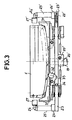
- This support device comprises a means for pre-positioning the part secured to the base. As shown in Figures 2 and 3, this pre-positioning means is constituted by two crosspieces 30 and 30 'fixed on the base 20. At each end of the crosspieces is fixed a support plate 31, 31'. The four support plates 31, 31 ′ are parallel to the side members 23 and 23 ′. On the other hand, to properly receive the screen E, the upper surface of the support plates have recesses which adapt to the front surface of the screen.
- the device for holding in position comprises four support points 32.
- each support point is each fixed to the end of a lever 33 the other end of which is pivotally mounted on the 'base 20.
- the four support points are positioned on the base such that two support points are parallel to the side members 23 and two other support points are parallel to the side members 23'.
- each spar has two stop elements 34. The stop elements are positioned on the spars so that, in the clamping position, the lower surface of each lever 33 abuts against one of the elements 34. From this done, the height of the support points 32 will depend on the spacing between the two beams. By correctly profiling the lower surface of the levers 33, it is therefore possible to adjust the height of the support points so as to obtain the same working height whatever the dimensions of the screen E used.
- the present invention has been described with reference to a screen for cathode ray tubes; it is obvious to those skilled in the art that the device of the present invention can also be used for clamping all parts of substantially parallelepidedic shape.
Landscapes
- Engineering & Computer Science (AREA)
- Manufacturing & Machinery (AREA)
- Devices For Indicating Variable Information By Combining Individual Elements (AREA)
- Formation Of Various Coating Films On Cathode Ray Tubes And Lamps (AREA)
- Jigs For Machine Tools (AREA)
- Supports Or Holders For Household Use (AREA)
- Manufacture Of Electron Tubes, Discharge Lamp Vessels, Lead-In Wires, And The Like (AREA)
Applications Claiming Priority (2)
| Application Number | Priority Date | Filing Date | Title |
|---|---|---|---|
| FR8715672 | 1987-11-13 | ||
| FR8715672A FR2623328B1 (fr) | 1987-11-13 | 1987-11-13 | Dispositif de maintien en position d'une piece de forme sensiblement parallelepipedique |
Publications (1)
| Publication Number | Publication Date |
|---|---|
| EP0317391A1 true EP0317391A1 (fr) | 1989-05-24 |
Family
ID=9356738
Family Applications (1)
| Application Number | Title | Priority Date | Filing Date |
|---|---|---|---|
| EP88402805A Withdrawn EP0317391A1 (fr) | 1987-11-13 | 1988-11-08 | Dispositif de maintien en position d'une pièce de forme sensiblement parallélépipédique |
Country Status (6)
| Country | Link |
|---|---|
| US (1) | US4907999A (ja) |
| EP (1) | EP0317391A1 (ja) |
| JP (1) | JPH01153233A (ja) |
| KR (1) | KR890008884A (ja) |
| CN (1) | CN1033124A (ja) |
| FR (1) | FR2623328B1 (ja) |
Cited By (1)
| Publication number | Priority date | Publication date | Assignee | Title |
|---|---|---|---|---|
| EP0510547A1 (en) * | 1991-04-23 | 1992-10-28 | Sony Corporation | Cathode ray tube positioning device |
Families Citing this family (7)
| Publication number | Priority date | Publication date | Assignee | Title |
|---|---|---|---|---|
| JP3848102B2 (ja) * | 2001-05-22 | 2006-11-22 | 富士通メディアデバイス株式会社 | 電子デバイスの封止装置及びその封止方法 |
| US6634915B2 (en) * | 2001-06-07 | 2003-10-21 | Sony Corporation | Apparatus and method for rotating and inspecting cathode-ray tube panels |
| CN100496884C (zh) * | 2002-08-19 | 2009-06-10 | Uht株式会社 | 工件保持装置 |
| CN101839388B (zh) * | 2010-05-18 | 2011-09-07 | 河海大学 | 一种适于工字形钢架结构的仪器安装平台 |
| CN102620129B (zh) * | 2012-04-10 | 2013-12-11 | 肯岦(上海)实业有限公司 | 一种支撑架 |
| CN109386693B (zh) * | 2018-10-19 | 2020-10-16 | 惠安县锋创商贸有限公司 | 船舶吊装托架自动锁紧支撑装置 |
| CN113581744B (zh) * | 2021-07-16 | 2022-11-08 | 淮北合众机械设备有限公司 | 一种可实现快速检修更换滚筒的磁悬浮式缓冲床 |
Citations (2)
| Publication number | Priority date | Publication date | Assignee | Title |
|---|---|---|---|---|
| FR2500213A1 (fr) * | 1981-02-19 | 1982-08-20 | Rca Corp | Dispositif pour appliquer une peinture conductrice sur les elements de support du panneau frontal d'un cinescope en couleur |
| FR2536907A1 (fr) * | 1982-11-26 | 1984-06-01 | Hitachi Ltd | Palette utilisee dans la fabrication de tubes a rayons cathodiques pour images en couleurs |
Family Cites Families (4)
| Publication number | Priority date | Publication date | Assignee | Title |
|---|---|---|---|---|
| US1111878A (en) * | 1910-11-28 | 1914-09-29 | Morgan Construction Co | Wire-gripping mechanism. |
| US4133570A (en) * | 1977-07-22 | 1979-01-09 | B. V. Nederlandse Kraanbouw Maatschappij Nkm | Hoisting apparatus having improved clamping means |
| US4258928A (en) * | 1977-12-12 | 1981-03-31 | Teledyne, Inc. | Precision positioning device |
| US4480181A (en) * | 1982-12-23 | 1984-10-30 | Fisher Charles R | Card capture device |
-
1987
- 1987-11-13 FR FR8715672A patent/FR2623328B1/fr not_active Expired - Fee Related
-
1988
- 1988-11-08 EP EP88402805A patent/EP0317391A1/fr not_active Withdrawn
- 1988-11-08 JP JP63282302A patent/JPH01153233A/ja active Pending
- 1988-11-10 US US07/269,705 patent/US4907999A/en not_active Expired - Fee Related
- 1988-11-11 KR KR1019880014815A patent/KR890008884A/ko not_active Application Discontinuation
- 1988-11-11 CN CN88107841A patent/CN1033124A/zh active Pending
Patent Citations (2)
| Publication number | Priority date | Publication date | Assignee | Title |
|---|---|---|---|---|
| FR2500213A1 (fr) * | 1981-02-19 | 1982-08-20 | Rca Corp | Dispositif pour appliquer une peinture conductrice sur les elements de support du panneau frontal d'un cinescope en couleur |
| FR2536907A1 (fr) * | 1982-11-26 | 1984-06-01 | Hitachi Ltd | Palette utilisee dans la fabrication de tubes a rayons cathodiques pour images en couleurs |
Cited By (2)
| Publication number | Priority date | Publication date | Assignee | Title |
|---|---|---|---|---|
| EP0510547A1 (en) * | 1991-04-23 | 1992-10-28 | Sony Corporation | Cathode ray tube positioning device |
| US5194028A (en) * | 1991-04-23 | 1993-03-16 | Sony Corporation | Cathode ray tube positioning device |
Also Published As
| Publication number | Publication date |
|---|---|
| US4907999A (en) | 1990-03-13 |
| FR2623328B1 (fr) | 1990-02-16 |
| KR890008884A (ko) | 1989-07-13 |
| CN1033124A (zh) | 1989-05-24 |
| FR2623328A1 (fr) | 1989-05-19 |
| JPH01153233A (ja) | 1989-06-15 |
Similar Documents
| Publication | Publication Date | Title |
|---|---|---|
| EP1166687B1 (fr) | Présentoir de marchandises | |
| FR2770292A1 (fr) | Dispositif de pesage de recipients par prehension en porte-a-faux | |
| FR2589588A1 (fr) | Appareil de polissage de fibres optiques mutiples | |
| CH691045A5 (fr) | Procédé pour l'orientation de plusieurs pièces cristallines posées côte à côte sur un support de découpage en vue d'une découpe simultanée dans une machine de découpage et dispositif pour la | |
| FR2779677A1 (fr) | Appareil manuel a couper les carreaux | |
| EP0317391A1 (fr) | Dispositif de maintien en position d'une pièce de forme sensiblement parallélépipédique | |
| EP0080960B1 (fr) | Dispositif à mâchoires orientables, adaptable sur tout support pour assurer de manière stable un serrage, un assemblage, un écartement ou un maintien en position de pièces de formes et dimensions quelconques | |
| WO1998028110A1 (fr) | Outil pilote de centrage et serrage | |
| FR2629003A1 (fr) | Dispositif pour compenser des tolerances de position | |
| FR2845959A1 (fr) | Appareil de travail guide a la main. | |
| FR2527965A1 (fr) | Dispositif de guidage en translation | |
| EP0551263B1 (fr) | Procede et dispositif pour animer une surface d'un mouvement de va-et-vient dans un plan | |
| FR2612100A1 (fr) | Dispositif de blocage rentrant, pour mandrin de tour ou analogue | |
| EP0589771A1 (fr) | Dispositif de fabrication de cartes à puces | |
| FR2636554A1 (fr) | Dispositif de soudage de toles ou analogues par un faisceau laser | |
| FR2511910A1 (fr) | Machine a souder sous vide utilisant un faisceau d'energie | |
| FR2494399A1 (fr) | Support reglable | |
| EP0041414B1 (fr) | Presse-étau perfectionnée | |
| EP0636448B1 (fr) | Unité d'indexation précise d'une palette dans le référentiel d'un poste de travail | |
| FR2639922A1 (fr) | Dispositif extensible de stockage d'objets plats | |
| FR2491420A1 (fr) | Chariot individuel repliable | |
| BE1006875A5 (fr) | Mecanisme echangeur de stylets dans une machine a dessiner automatique. | |
| EP0839605B1 (fr) | Porte-monture de lunettes | |
| EP0421117A1 (fr) | Tête d'usinage à faisceau laser | |
| CA1326246C (fr) | Dispositif de serrage de cadres |
Legal Events
| Date | Code | Title | Description |
|---|---|---|---|
| PUAI | Public reference made under article 153(3) epc to a published international application that has entered the european phase |
Free format text: ORIGINAL CODE: 0009012 |
|
| AK | Designated contracting states |
Kind code of ref document: A1 Designated state(s): DE GB IT NL |
|
| 17P | Request for examination filed |
Effective date: 19890606 |
|
| STAA | Information on the status of an ep patent application or granted ep patent |
Free format text: STATUS: THE APPLICATION HAS BEEN WITHDRAWN |
|
| 18W | Application withdrawn |
Withdrawal date: 19910119 |
|
| R18W | Application withdrawn (corrected) |
Effective date: 19910119 |