EP0317391A1 - Device for maintaining in position approximately parallelepipedically shaped parts - Google Patents
Device for maintaining in position approximately parallelepipedically shaped parts Download PDFInfo
- Publication number
- EP0317391A1 EP0317391A1 EP88402805A EP88402805A EP0317391A1 EP 0317391 A1 EP0317391 A1 EP 0317391A1 EP 88402805 A EP88402805 A EP 88402805A EP 88402805 A EP88402805 A EP 88402805A EP 0317391 A1 EP0317391 A1 EP 0317391A1
- Authority
- EP
- European Patent Office
- Prior art keywords
- fixed
- support
- base
- support elements
- support element
- Prior art date
- Legal status (The legal status is an assumption and is not a legal conclusion. Google has not performed a legal analysis and makes no representation as to the accuracy of the status listed.)
- Withdrawn
Links
Images


Classifications
-
- H—ELECTRICITY
- H01—ELECTRIC ELEMENTS
- H01J—ELECTRIC DISCHARGE TUBES OR DISCHARGE LAMPS
- H01J9/00—Apparatus or processes specially adapted for the manufacture, installation, removal, maintenance of electric discharge tubes, discharge lamps, or parts thereof; Recovery of material from discharge tubes or lamps
- H01J9/24—Manufacture or joining of vessels, leading-in conductors or bases
-
- H—ELECTRICITY
- H01—ELECTRIC ELEMENTS
- H01J—ELECTRIC DISCHARGE TUBES OR DISCHARGE LAMPS
- H01J9/00—Apparatus or processes specially adapted for the manufacture, installation, removal, maintenance of electric discharge tubes, discharge lamps, or parts thereof; Recovery of material from discharge tubes or lamps
-
- Y—GENERAL TAGGING OF NEW TECHNOLOGICAL DEVELOPMENTS; GENERAL TAGGING OF CROSS-SECTIONAL TECHNOLOGIES SPANNING OVER SEVERAL SECTIONS OF THE IPC; TECHNICAL SUBJECTS COVERED BY FORMER USPC CROSS-REFERENCE ART COLLECTIONS [XRACs] AND DIGESTS
- Y10—TECHNICAL SUBJECTS COVERED BY FORMER USPC
- Y10S—TECHNICAL SUBJECTS COVERED BY FORMER USPC CROSS-REFERENCE ART COLLECTIONS [XRACs] AND DIGESTS
- Y10S269/00—Work holders
- Y10S269/908—Work holder for cathode-ray tubes
Definitions
- the present invention relates to a device for holding in position a part of substantially rectangular shape, more particularly, a device for holding in position the screens of cathode-ray tubes.
- Such position holding devices or screen clamping devices can be used at any point in the production chain. However, they are mainly used in rooms for depositing luminescent substances on the screen.
- the devices for holding in position the cathode ray tube screens currently used consist essentially of a base 1 which can be, for example, a rectangular frame whose two long sides each have two fixed support points 2 intended to receive the front surface of the screen.
- a first support element constituted by a vertical post 3 on which an arm 4 is fixed perpendicularly carrying at each end a sleeve 5.
- the sleeve 5 is preferably made of an elastic material such as rubber.
- On the other short side of the base 1 is mounted for rotation about the axis A a second support element.
- This second support element is constituted by a vertical post 3 ′ at the upper end of which is fixed perpendicularly an arm 4 ′ also comprising at its two ends a sleeve 5 ′ made of an elastic material.
- the base 1 comprises a hub intended to receive a vertical shaft 12.
- This vertical shaft is fixed on an operating head.
- this operating head essentially comprises a frame 8 on which is fixed a perpendicular console 9.
- a hollow sleeve 11 At the end of the console is mounted, pivotally about the axis 10, a hollow sleeve 11.
- L 'shaft 12 is inserted into the sleeve 11. It passes through the hub 7 and is fixed in position by means of a screw system.
- This system allows the adjustment of the working height of the screen.
- working height is meant the distance between the pivot point 10 and the plane P determining the weld edge of the screen on the cone. This device can only function correctly with screens having all the same dimensions.
- the object of the present invention is to remedy the drawbacks mentioned above by proposing a new device for holding in position for parts of substantially parallelepiped shape such as screens for cathode ray tubes.
- the subject of the present invention is a device for holding in position a part of substantially parallelepiped shape of the type comprising, fixed to a base, a support device on which the part comes to rest and at least two support elements coming from clamp the part on two opposite sides, characterized in that the two support elements are fixed on a deformable quadrilateral so as to have between the two support elements a continuously variable spacing.
- the deformable quadrilateral is constituted by two arms of the same length articulated in their middle on the base and by two longitudinal members articulated respectively at the opposite ends of the two arms, a support element being fixed at one end d 'a spar while the other support element is fixed to the other end of the other spar.
- the device further comprises means urging the two support elements in their position of minimum spacing.
- This means urging the two support elements in their minimum spacing position consists of at least one spring fixed between the two support elements.
- the means urging the two support elements in their position of minimum spacing consists of two springs each fixed between a support element and the end of the beam of the other support element.
- the support device comprises a means for pre-positioning the part integral with the base and at least three support points fixed on the base so as to be able to move vertically.
- each fulcrum is provided at the end of a lever articulated on the base, the position of said lever being fixed by a stop secured to one of the side members.
- the device for holding in position essentially comprises a base 20.
- This base has a hub 20 ′ allowing the passage of the shaft of the operating head, and a device 20 ⁇ allowing the tightening of the shaft inside the hub.
- two arms 21 and 21 ′ of the same length are articulated in the middle at each end of the base 20 as shown by the points 22 and 22 ′ in FIG. 2.
- two side members 23 and 23 ′ are articulated respectively at the opposite ends of the two arms 21 and 21 ′ so as to form a deformable quadrilateral.
- a perpendicular arm 24 is fixed at the end of the spar 23 located on the side of the arm 21 ′.
- a vertical post 25 which supports in its middle a horizontal arm 26 at each end of which sleeves are mounted 27 made of an elastic material such as rubber.
- These elements 24, 25, 26 and 27 form a first support element.
- a second support element consisting of the arm 24 ′, the post 25 ′, the arm 26 ′, and two sleeves 27 ′, is mounted at the end of the beam 23 ′ located on the side of the arm 21
- two springs 28 and 28 ′ are provided respectively between the arm 24 and the opposite end of the spar 23 ′ or between the arm 24 ′ and the opposite end of the spar 23. These two springs keep the two support elements in their position of minimum spacing as will be explained below.
- the positioning of the screen E is carried out in the following manner.
- This thrust exerted on one of the beams causes a movement in the opposite direction of the other beam, which separates the two support elements from one another. It is then possible to introduce the screen E between these two support elements.
- the return force of the springs 28 and 28 ′ brings the two support elements in contact with the skirt of the screen E.
- the two support elements move symmetrically and by the same distance relative to the axis of the device which corresponds to the axis of the operating head. Therefore, if the screen E is centered correctly in the device, there is no risk of sliding between the support points and the glass. On the other hand, such a device can adapt to any screen size without centering problem due to this symmetrical displacement.
- the position holding device further comprises a support device on which the part comes to rest before it is clamped between the two support elements.
- This support device comprises a means for pre-positioning the part secured to the base. As shown in Figures 2 and 3, this pre-positioning means is constituted by two crosspieces 30 and 30 'fixed on the base 20. At each end of the crosspieces is fixed a support plate 31, 31'. The four support plates 31, 31 ′ are parallel to the side members 23 and 23 ′. On the other hand, to properly receive the screen E, the upper surface of the support plates have recesses which adapt to the front surface of the screen.
- the device for holding in position comprises four support points 32.
- each support point is each fixed to the end of a lever 33 the other end of which is pivotally mounted on the 'base 20.
- the four support points are positioned on the base such that two support points are parallel to the side members 23 and two other support points are parallel to the side members 23'.
- each spar has two stop elements 34. The stop elements are positioned on the spars so that, in the clamping position, the lower surface of each lever 33 abuts against one of the elements 34. From this done, the height of the support points 32 will depend on the spacing between the two beams. By correctly profiling the lower surface of the levers 33, it is therefore possible to adjust the height of the support points so as to obtain the same working height whatever the dimensions of the screen E used.
- the present invention has been described with reference to a screen for cathode ray tubes; it is obvious to those skilled in the art that the device of the present invention can also be used for clamping all parts of substantially parallelepidedic shape.
Abstract
Description
La présente invention concerne un dispositif de maintien en position d'une pièce de forme sensiblement parallélépidèdique, plus particulièrement, un dispositif de maintien en position des écrans de tubes cathodiques.The present invention relates to a device for holding in position a part of substantially rectangular shape, more particularly, a device for holding in position the screens of cathode-ray tubes.
Dans le cas des tubes cathodiques, de tels dispositifs de maintien en position ou dispositifs de serrage des écrans peuvent être utilisés en n'importe quel point de la chaîne de fabrication. Toutefois, ils sont surtout utilisés dans les salles de dépôt des substances luminescentes sur l'écran.In the case of cathode ray tubes, such position holding devices or screen clamping devices can be used at any point in the production chain. However, they are mainly used in rooms for depositing luminescent substances on the screen.
Comme représenté sur la figure 1, les dispositifs de maintien en position des écrans de tubes cathodiques actuellement utilisés sont constitués essentiellement par une embase 1 qui peut être, par exemple, un cadre rectangulaire dont les deux grands côtés comportent chacun deux points d'appui fixes 2 destinés à recevoir la surface frontale de l'écran. D'autre part, sur l'un des petits côtés de l'embase 1 est monté de manière fixe un premier élément d'appui constitué par un poteau vertical 3 sur lequel est fixé perpendiculairement un bras 4 portant à chaque extrémité un manchon 5. Le manchon 5 est, de préférence, réalisé en un matériau élastique tel que du caoutchouc. Sur l'autre petit côté de l'embase 1 est monté à rotation autour de l'axe A un second élément d'appui. Ce second élément d'appui est constitué par un poteau vertical 3′ à l'extrémité supérieure duquel est fixé perpendiculairement un bras 4′ comportant lui aussi à ses deux extrémités un manchon 5′ en un matériau élastique. Avec ce dispositif, la face avant de l'écran E est placée en appui sur les quatre points d'appui 2. Puis cet écran est translaté de telle sorte qu'un des côtés de la jupe J de l'écran vienne en appui contre les deux manchons 5 de l'élément support fixe. Pendant ce temps, l'élément support mobile 3′ est maintenu écarté pour permettre le positionnement de l'écran. Puis, l'élément support mobile est amené en appui contre l'autre côté de la jupe en libérant un ressort 6 et un bouton poussoir 6′, ce qui provoque le serrage de l'élément support mobile contre l'écran. D'autre part, l'embase 1 comporte un moyeu destiné à recevoir un arbre vertical 12. Cet arbre vertical est fixé sur une tête opératrice. Comme représenté sur la figure 1, cette tête opératrice comporte essentiellement un bâti 8 sur lequel est fixée une console perpendiculaire 9. A l'extrémité de la console est monté, de manière pivotante autour de l'axe 10, un manchon creux 11. L'arbre 12 est inséré dans le manchon 11. Il traverse le moyeu 7 et est fixé en position par l'intermédiaire d'un système à vis. Ce système permet le réglage de la hauteur de travail de l'écran. Par hauteur de travail, on entend la distance entre le point de pivotement 10 et le plan P déterminant le bord de soudure de l'écran sur le cône. Ce dispositif ne peut fonctionner correctement qu'avec des écrans présentant tous les mêmes dimensions. En effet, l'utilisation d'un élément support fixe et d'un élément support mobile nécessite des écrans de même longueur pour obtenir un centrage correct de l'écran. Si un tel centrage n'est pas obtenu, on observe des vibrations importantes sur la tête opératrice ce qui entraîne de nombreux déchets de fabrication. De plus, lors du centrage, il y a toujours un léger glissement de la surface de l'écan sur les points d'appui, ce qui provoque des rainures sur la dalle en verre. D'autre part, avec des écrans de hauteurs différentes, la hauteur de travail n'est pas respectée et certaines opérations telles que la soudure ou autres ne peuvent pas être réalisées. Ce type de dispositif limite donc la flexibilité de la chaîne de fabrication.As shown in FIG. 1, the devices for holding in position the cathode ray tube screens currently used consist essentially of a base 1 which can be, for example, a rectangular frame whose two long sides each have two fixed support points 2 intended to receive the front surface of the screen. On the other hand, on one of the short sides of the base 1 is fixedly mounted a first support element constituted by a
La présente invention a pour but de remédier aux inconvénients mentionnés ci-dessus en proposant un nouveau dispositif de maintien en position pour des pièces de forme sensiblement parallélépipèdiques telles que des écrans pour tubes cathodiques.The object of the present invention is to remedy the drawbacks mentioned above by proposing a new device for holding in position for parts of substantially parallelepiped shape such as screens for cathode ray tubes.
En conséquence, la présent invention a pour objet un dispositif de maintien en position d'une pièce de forme sensiblement parallélépipèdique du type comportant, fixés sur une embase, un dispositif support sur lequel vient reposer la pièce et au moins deux éléments d'appui venant serrer la pièce sur deux côtés opposés, caractérisé en ce que les deux éléments d'appui sont fixés sur un quadrilatère déformable de manière à avoir entre les deux éléments d'appui un écartement continuement variable.Consequently, the subject of the present invention is a device for holding in position a part of substantially parallelepiped shape of the type comprising, fixed to a base, a support device on which the part comes to rest and at least two support elements coming from clamp the part on two opposite sides, characterized in that the two support elements are fixed on a deformable quadrilateral so as to have between the two support elements a continuously variable spacing.
Selon un mode de réalisation préférentiel, le quadrilatère déformable est constitué par deux bras de même longueur articulés en leur milieu sur l'embase et par deux longerons articulés respectivement aux extrémités opposées des deux bras, un élément d'appui étant fixé à une extrémité d'un longeron tandis que l'autre élément d'appui est fixé à l'autre extrémité de l'autre longeron.According to a preferred embodiment, the deformable quadrilateral is constituted by two arms of the same length articulated in their middle on the base and by two longitudinal members articulated respectively at the opposite ends of the two arms, a support element being fixed at one end d 'a spar while the other support element is fixed to the other end of the other spar.
Selon une autre caractéristique de l'invention, le dispositif comporte de plus un moyen sollicitant les deux éléments d'appui dans leur position d'écartement minimal. Ce moyen sollicitant les deux éléments d'appui dans leur position d'écartement minimal est constitué par au moins un ressort fixé entre les deux éléments d'appui. De préférence, le moyen sollicitant les deux éléments d'appui dans leur position d'écartement minimal est constitué par deux ressorts fixés chacun entre un élément d'appui et l'extrémité du longeron de l'autre élément d'appui. Avec ce dispositif, on obtient un centrage correct de la pièce quelles que soient ses dimensions.According to another characteristic of the invention, the device further comprises means urging the two support elements in their position of minimum spacing. This means urging the two support elements in their minimum spacing position consists of at least one spring fixed between the two support elements. Preferably, the means urging the two support elements in their position of minimum spacing consists of two springs each fixed between a support element and the end of the beam of the other support element. With this device, a correct centering of the part is obtained whatever its dimensions.
Selon une autre caractéristique de la présente invention, le dispositif support comporte un moyen de pré-positionnement de la pièce solidaire de l'embase et au moins trois points d'appui fixés sur l'embase de manière à pouvoir se déplacer verticalement.According to another characteristic of the present invention, the support device comprises a means for pre-positioning the part integral with the base and at least three support points fixed on the base so as to be able to move vertically.
Selon un mode de réalisation préférentiel, chaque point d'appui est prévu à l'extrémité d'un levier articulé sur l'embase, la position dudit levier étant fixée par une butée solidaire d'un des longerons. Cette disposition des points d'appui permet de régler la hauteur de travail en fonction de la hauteur de la pièce parallélépipèdique.According to a preferred embodiment, each fulcrum is provided at the end of a lever articulated on the base, the position of said lever being fixed by a stop secured to one of the side members. This arrangement of the support points makes it possible to adjust the working height as a function of the height of the parallelepiped piece.
D'autres caractéristiques et avantages de la présente invention apparaîtront à la lecture de la description d'un mode de réalisation préférentiel faite ci-après avec référence aux dessins ci-annexés dans lesquels :
- - la figure 1, déjà décrite, est une vue schématique en élèvation d'un dispositif conforme à l'art antérieur ;
- - la figure 2 est une vue en plan de dessus partiellement éclatée d'un dispositif de maintien en position conforme à la présente invention, et
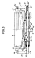
- la figure 3 est une vue schématique en élévation du dispositif de la figure 2.
- - Figure 1, already described, is a schematic elevation of a device according to the prior art;
- FIG. 2 is a partially exploded top plan view of a position holding device according to the present invention, and
- Figure 3 is a schematic elevational view of the device of Figure 2.
Comme représenté sur les figures 2 et 3, le dispositif de maintien en position conforme à la présente invention comporte essentiellement une embase 20. Cette embase comporte un moyeu 20′ permettant le passage de l'arbre de la tête opératrice, et un dispositif 20˝ permettant le serrage de l'arbre à l'intérieur du moyeu. Conformément à la présente invention, deux bras 21 et 21′ de même longueur sont articulés en leur milieu à chaque extrémité de l'embase 20 comme représenté par les points 22 et 22′ sur la figure 2. D'autre part, deux longerons 23 et 23′ sont articulés respectivement aux extrémités opposées des deux bras 21 et 21′ de manière à former un quadrilatère déformable. A l'extrémité du longeron 23 se trouvant du côté du bras 21′, est fixé un bras perpendiculaire 24. Sur ce bras 24 est vissé un poteau vertical 25 qui supporte en son milieu un bras horizontal 26 à chaque extrémité duquel sont montés des manchons 27 en un matériau élastique tel que du caoutchouc. Ces éléments 24,25,26 et 27 forment un premier élément d'appui. De manière similaire, un second élément d'appui constitué du bras 24′, du poteau 25′, du bras 26′, et de deux manchons 27′, est monté à l'extrémité du longeron 23′ se trouvant du côté du bras 21. De plus, deux ressorts 28 et 28′ sont prévus respectivement entre le bras 24 et l'extrémité opposée du longeron 23′ ou entre le bras 24′ et l'extrémité opposée du longeron 23. Ces deux ressorts permettent de maintenir les deux éléments d'appui dans leur position d'écartement minimal comme cela sera expliqué ci-après.As shown in Figures 2 and 3, the device for holding in position according to the present invention essentially comprises a
Avec le dispositif décrit ci-dessus, le positionnement de l'écran E est réalisé de la manière suivante. On exerce sur un des longerons une poussée supérieure à la force exercée par les ressorts 28 et 28′. Cette poussée exercée sur l'un des longerons entraîne un mouvement en sens opposé de l'autre longeron, ce qui écarte les deux éléments d'appui l'un de l'autre. Il est alors possible d'introduire l'écran E entre ces deux éléments d'appui. Lorsque l'on arrête d'exercer une poussée sur l'un des longerons, la force de rappel des ressorts 28 et 28′ amène les deux éléments d'appui en contact avec la jupe de l'écran E. Comme les longerons et les deux bras 21 et 21′ forment un quadrilatère articulé, les deux éléments d'appui se déplacent symétriquement et de la même distance par rapport à l'axe du dispositif qui correspond à l'axe de la tête opératrice. De ce fait, si l'écran E est centré correctement dans le dispositif, il n'y a aucun risque de glissement entre les points d'appui et le verre. D'autre part, un tel dispositif peut s'adapter à toutes dimensions d'écran sans problème de centrage du fait de ce déplacement symétrique.With the device described above, the positioning of the screen E is carried out in the following manner. One exerts on one of the side members a thrust greater than the force exerted by the
Le dispositif de maintien en position conforme à la présente invention comporte de plus un dispositif support sur lequel vient reposer la pièce avant son serrage entre les deux éléments d'appui. Ce dispositif support comporte un moyen de pré-positionnement de la pièce solidaire de l'embase. Comme représenté sur les figures 2 et 3, ce moyen de pré-positionnement est constitué par deux traverses 30 et 30′ fixées sur l'embase 20. A chaque extrémité des traverses est fixée une plaque support 31, 31′. Les quatre plaques support 31, 31′ sont parallèles aux longerons 23 et 23′. D'autre part, pour recevoir correctement l'écran E, la surface supérieure des plaques support présentent des décrochements qui s'adaptent à la surface frontale de l'écran. De plus, conformément à la présente invention, le dispositif de maintien en position comporte quatre points d'appui 32. Ces points d'appui sont chacun fixés à l'extrémité d'un levier 33 dont l'autre extrémité est montée pivotante sur l'embase 20. Les quatre points d'appui sont positionnés sur l'embase de telle sorte que deux points d'appui soient parallèles aux longerons 23 et deux autres points d'appui soient parallèles aux longerons 23′. D'autre part, chaque longeron comporte deux éléments formant butée 34. Les éléments formant butée sont positionnés sur les longerons de sorte que, en position de serrage, la surface inférieure de chaque levier 33 vienne en butée contre un des éléments 34. De ce fait, la hauteur des points d'appui 32 sera fonction de l'écartement entre les deux longerons. En profilant correctement la surface inférieure des leviers 33, il est donc possible de régler la hauteur des points d'appui de manière à obtenir la même hauteur de travail quelles que soient les dimensions de l'écran E utilisé.The position holding device according to the present invention further comprises a support device on which the part comes to rest before it is clamped between the two support elements. This support device comprises a means for pre-positioning the part secured to the base. As shown in Figures 2 and 3, this pre-positioning means is constituted by two
La présente invention a été décrite en se référant à un écran pour tubes cathodiques ; il est évident pour l'homme de l'art que le dispositif de la présente invention peut aussi être utilisé pour le serrage de toutes pièces de forme sensiblement parallélépidèdique.The present invention has been described with reference to a screen for cathode ray tubes; it is obvious to those skilled in the art that the device of the present invention can also be used for clamping all parts of substantially parallelepidedic shape.
Claims (7)
Applications Claiming Priority (2)
| Application Number | Priority Date | Filing Date | Title |
|---|---|---|---|
| FR8715672 | 1987-11-13 | ||
| FR8715672A FR2623328B1 (en) | 1987-11-13 | 1987-11-13 | DEVICE FOR HOLDING A POSITION OF A SUBSTANTIALLY PARALLELEPIPEDIC SHAPE |
Publications (1)
| Publication Number | Publication Date |
|---|---|
| EP0317391A1 true EP0317391A1 (en) | 1989-05-24 |
Family
ID=9356738
Family Applications (1)
| Application Number | Title | Priority Date | Filing Date |
|---|---|---|---|
| EP88402805A Withdrawn EP0317391A1 (en) | 1987-11-13 | 1988-11-08 | Device for maintaining in position approximately parallelepipedically shaped parts |
Country Status (6)
| Country | Link |
|---|---|
| US (1) | US4907999A (en) |
| EP (1) | EP0317391A1 (en) |
| JP (1) | JPH01153233A (en) |
| KR (1) | KR890008884A (en) |
| CN (1) | CN1033124A (en) |
| FR (1) | FR2623328B1 (en) |
Cited By (1)
| Publication number | Priority date | Publication date | Assignee | Title |
|---|---|---|---|---|
| EP0510547A1 (en) * | 1991-04-23 | 1992-10-28 | Sony Corporation | Cathode ray tube positioning device |
Families Citing this family (7)
| Publication number | Priority date | Publication date | Assignee | Title |
|---|---|---|---|---|
| JP3848102B2 (en) * | 2001-05-22 | 2006-11-22 | 富士通メディアデバイス株式会社 | Electronic device sealing apparatus and sealing method thereof |
| US6634915B2 (en) * | 2001-06-07 | 2003-10-21 | Sony Corporation | Apparatus and method for rotating and inspecting cathode-ray tube panels |
| CN100496884C (en) * | 2002-08-19 | 2009-06-10 | Uht株式会社 | Workpiece holding device |
| CN101839388B (en) * | 2010-05-18 | 2011-09-07 | 河海大学 | Instrument mounting platform applied to I-shaped steel frame structure |
| CN102620129B (en) * | 2012-04-10 | 2013-12-11 | 肯岦(上海)实业有限公司 | Supporting frame |
| CN109386693B (en) * | 2018-10-19 | 2020-10-16 | 惠安县锋创商贸有限公司 | Automatic locking and supporting device for ship hoisting bracket |
| CN113581744B (en) * | 2021-07-16 | 2022-11-08 | 淮北合众机械设备有限公司 | Magnetic suspension type buffer bed capable of realizing quick maintenance and replacement of roller |
Citations (2)
| Publication number | Priority date | Publication date | Assignee | Title |
|---|---|---|---|---|
| FR2500213A1 (en) * | 1981-02-19 | 1982-08-20 | Rca Corp | DEVICE FOR APPLYING CONDUCTIVE PAINT TO THE SUPPORT ELEMENTS OF THE FRONT PANEL OF A COLORED CINESCOPE |
| FR2536907A1 (en) * | 1982-11-26 | 1984-06-01 | Hitachi Ltd | PALLET USED IN THE MANUFACTURE OF CATHODE-RAY TUBES FOR COLOR IMAGES |
Family Cites Families (4)
| Publication number | Priority date | Publication date | Assignee | Title |
|---|---|---|---|---|
| US1111878A (en) * | 1910-11-28 | 1914-09-29 | Morgan Construction Co | Wire-gripping mechanism. |
| US4133570A (en) * | 1977-07-22 | 1979-01-09 | B. V. Nederlandse Kraanbouw Maatschappij Nkm | Hoisting apparatus having improved clamping means |
| US4258928A (en) * | 1977-12-12 | 1981-03-31 | Teledyne, Inc. | Precision positioning device |
| US4480181A (en) * | 1982-12-23 | 1984-10-30 | Fisher Charles R | Card capture device |
-
1987
- 1987-11-13 FR FR8715672A patent/FR2623328B1/en not_active Expired - Fee Related
-
1988
- 1988-11-08 JP JP63282302A patent/JPH01153233A/en active Pending
- 1988-11-08 EP EP88402805A patent/EP0317391A1/en not_active Withdrawn
- 1988-11-10 US US07/269,705 patent/US4907999A/en not_active Expired - Fee Related
- 1988-11-11 CN CN88107841A patent/CN1033124A/en active Pending
- 1988-11-11 KR KR1019880014815A patent/KR890008884A/en not_active Application Discontinuation
Patent Citations (2)
| Publication number | Priority date | Publication date | Assignee | Title |
|---|---|---|---|---|
| FR2500213A1 (en) * | 1981-02-19 | 1982-08-20 | Rca Corp | DEVICE FOR APPLYING CONDUCTIVE PAINT TO THE SUPPORT ELEMENTS OF THE FRONT PANEL OF A COLORED CINESCOPE |
| FR2536907A1 (en) * | 1982-11-26 | 1984-06-01 | Hitachi Ltd | PALLET USED IN THE MANUFACTURE OF CATHODE-RAY TUBES FOR COLOR IMAGES |
Cited By (2)
| Publication number | Priority date | Publication date | Assignee | Title |
|---|---|---|---|---|
| EP0510547A1 (en) * | 1991-04-23 | 1992-10-28 | Sony Corporation | Cathode ray tube positioning device |
| US5194028A (en) * | 1991-04-23 | 1993-03-16 | Sony Corporation | Cathode ray tube positioning device |
Also Published As
| Publication number | Publication date |
|---|---|
| JPH01153233A (en) | 1989-06-15 |
| CN1033124A (en) | 1989-05-24 |
| US4907999A (en) | 1990-03-13 |
| FR2623328B1 (en) | 1990-02-16 |
| FR2623328A1 (en) | 1989-05-19 |
| KR890008884A (en) | 1989-07-13 |
Similar Documents
| Publication | Publication Date | Title |
|---|---|---|
| EP1166687B1 (en) | Merchandising display | |
| FR2770292A1 (en) | Automatic filling apparatus for bottles or other containers | |
| CH691045A5 (en) | A method for the orientation of several crystalline parts placed side by side on a cutting support for a simultaneous cutting in a cutting machine and device for | |
| FR2804892A1 (en) | ADJUSTABLE GRIP MEMBER FOR TRANSPORTING OR MACHINING ANY SHAPED PART | |
| FR2779677A1 (en) | MANUAL TILE CUTTING APPARATUS | |
| EP0317391A1 (en) | Device for maintaining in position approximately parallelepipedically shaped parts | |
| FR2757437A1 (en) | PILOT CENTERING AND TIGHTENING TOOL | |
| EP0080960B1 (en) | Device with orientable jaws, adaptable to any support to assure in a stable way the holding, assembling, separating or keeping in position of workpieces of different shapes or dimensions | |
| FR2629003A1 (en) | DEVICE FOR COMPENSATING POSITION TOLERANCES | |
| FR2527965A1 (en) | Sliding guide for robot arm - uses pairs of rollers straddling opposite corners of section with their axes parallel and diagonal | |
| EP0551263B1 (en) | Process and device for causing a surface to reciprocate in a plane | |
| FR2612100A1 (en) | RETRACTING LOCKING DEVICE FOR TURN CHUCK OR THE LIKE | |
| EP0589771A1 (en) | Chip cards manufacturing device | |
| FR2636554A1 (en) | Device for welding metal sheets or the like using a laser beam | |
| EP0521775A1 (en) | Portable apparatus for straightening tubes | |
| FR2511910A1 (en) | VACUUM WELDING MACHINE USING AN ENERGY BEAM | |
| EP0636448B1 (en) | Precision indexing unit for a pallet relative to a work station | |
| FR2494399A1 (en) | Adjustable table for computer terminal - has pivoting base supporting height adjustable and tilting table with gas jacks compensating for terminal weight | |
| FR2639922A1 (en) | EXPANDABLE DEVICE FOR STORING FLAT OBJECTS | |
| BE1006875A5 (en) | Mechanism exchanger stylus in machine automatic draw. | |
| EP0220967A1 (en) | Conveyor for containers | |
| EP0839605B1 (en) | Spectacle frame holder | |
| EP0421117A1 (en) | Laser beam machining head | |
| CA1326246C (en) | Device for tightening frames | |
| EP0175164B1 (en) | Device for measuring the axial position of a work piece to be machined on a machine tool, especially on a grinding machine for external cylindrical surfaces |
Legal Events
| Date | Code | Title | Description |
|---|---|---|---|
| PUAI | Public reference made under article 153(3) epc to a published international application that has entered the european phase |
Free format text: ORIGINAL CODE: 0009012 |
|
| AK | Designated contracting states |
Kind code of ref document: A1 Designated state(s): DE GB IT NL |
|
| 17P | Request for examination filed |
Effective date: 19890606 |
|
| STAA | Information on the status of an ep patent application or granted ep patent |
Free format text: STATUS: THE APPLICATION HAS BEEN WITHDRAWN |
|
| 18W | Application withdrawn |
Withdrawal date: 19910119 |
|
| R18W | Application withdrawn (corrected) |
Effective date: 19910119 |