EP0317032B1 - Halter zum Befestigen von Dachrinnen - Google Patents
Halter zum Befestigen von Dachrinnen Download PDFInfo
- Publication number
- EP0317032B1 EP0317032B1 EP88202589A EP88202589A EP0317032B1 EP 0317032 B1 EP0317032 B1 EP 0317032B1 EP 88202589 A EP88202589 A EP 88202589A EP 88202589 A EP88202589 A EP 88202589A EP 0317032 B1 EP0317032 B1 EP 0317032B1
- Authority
- EP
- European Patent Office
- Prior art keywords
- bracket
- nut
- supporting part
- bore
- space
- Prior art date
- Legal status (The legal status is an assumption and is not a legal conclusion. Google has not performed a legal analysis and makes no representation as to the accuracy of the status listed.)
- Expired - Lifetime
Links
Images


Classifications
-
- E—FIXED CONSTRUCTIONS
- E04—BUILDING
- E04D—ROOF COVERINGS; SKY-LIGHTS; GUTTERS; ROOF-WORKING TOOLS
- E04D13/00—Special arrangements or devices in connection with roof coverings; Protection against birds; Roof drainage ; Sky-lights
- E04D13/04—Roof drainage; Drainage fittings in flat roofs, balconies or the like
- E04D13/064—Gutters
- E04D13/072—Hanging means
- E04D13/0722—Hanging means extending mainly under the gutter
Definitions
- the invention relates to a gutter bracket assembly according to the preamble of claim 1.
- a gutter bracket assembly of this type is known from DE-A-2945503.
- the supporting part consists of two parallel plates separated and connected to each other at one end by a spacer.
- the distance between theb plates is equal to the thickness of the roof's eaves, so that the supporting part can be slid over said eaves until the spacer abuts the edge of the eaves.
- the centre plate of said three plates has a depression for retaining the bracket in place in the supporting part after being slid therein.
- To maintain the supporting part of the roof's eaves at least one surface of the plates facing the eaves may be provided with teeth.
- said first two plates may each be provided with a bore for passing through a bolt which is then also passed through a bore provided in said eaves.
- the supporting part is provided with said bores, which might be necessary if there is a play between the eaves and the surfaces of the plates facing the eaves, it will be required that the bores to be provided in the eaves must be perfectly on one line, since otherwise the curved parts of different assemblies in a row for supporting the gutter may not be sufficiently in one line. Since a person mounting such assembly to the eaves must manipulate three elements while bringing in one line the bores of the supporting part and the bore of the eaves, this may lead to an unstable and unsafe condition for said person.
- the object of the invention is to eliminate said drawbacks of the prior art bracket assembly.
- This object is achieved for the gutter bracket assembly according to claim 1.
- a person needs only to manipulate the bolt, possibly having a spacer, and the supporting part having inserted therein firstly the nut and then the upper end part of the bracket. Therefore, this may prevent the occurence of an unstable and unsafe condition for the person while mounting the assembly to the roof's eaves.
- This advantage is deepened by that the positions of the supporting part and the bracket part can be adjusted with respect to each other and with respect to the bore provided in the eaves, so that the person can easily mount the assembly to the eaves while bringing the bracket parts of a row of bracket parts in line, possibly by first stretching a reference string.
- the upper end of the bracket is retained in the bracket receiving place of the supporting part by friction. Accordingly, one can assemble a number of said groups of elements, comprising the supporting part, the nut and the bracket part, in advance, just prior for mounting it to the eaves or even when manufacturing the assembly, possibly, with different types of brackets, whereby loss of the bracket out of the supporting part, such as during transportation or shortly prior or during mounting it to the eaves, is prevented.
- the bracket receiving space has on a wall thereof a projection which projects into said space providing a friction means for retaining the bracket upper end in the bracket receiving space of the supporting part.
- said protection may provide said friction between the supporting part and the bracket part.
- the object according to the invention is also achieved by the gutter bracket assembly according to claim 4.
- the bracket need not to be coupled to the supporting part in advance. Yet the nut will be retained in its nesting space once it has been pushed in it.
- this assembly may provide a means to easy adjust the position of a curved part of the bracket part intended to support the gutter where its angular position is concerned and its position in a row of brackets with which it should be aligned.
- a gutter bracket assembly having a supporting part and a bracket part which is to be connected to the supporting part, whereby the supporting part has nesting places for nuts.
- the assembly is however of a quite different type since the supporting part is to be mounted to a wall.
- the nut nesting places are such that one nut can be lost out of its nesting place if the associated screw is not firmly screwed in said nut, and that the other nut can be lost out of its nesting place if the associated screw is not at least partly screwed in it.
- this prior art assembly one has to manipulate more than two elements or groups of elements to mount the assembly to the wall.
- a gutter bracket assembly intended to be mounted to the eaves of a roof, comprising an elongated supporting part having an insertion space and a bracket part to be inserted into the insertion space.
- the bracket part has an elongated U-slot for passing through a bolt which is also passed through an elongated bore in the supporting part and a bore in the eaves. If the bolt is not firmly screwed in an associated nut, parts can fall apart.
- bracket part Since the upper end of the bracket part is curved and the insertion space of the supporting part is curved correspondingly, these parts cannot be shifted relative to each other in a direction perpendicular to the eaves' edge and the gutter, which limits the possibilities for adjusting the position of the assembly with regard to other assemblies in a row mounted to said eaves.
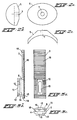
- the bracket unit according to the invention shown in Fig. 1, which is used with a corrugated sheet 1 of a roof, comprises an elongated supporting part 3 which is fitted against the bottom side of a corrugated ridge 2 of the corrugated sheet 1 and a bracket part 10 which is inserted into the supporting part 3, and a bottom end (not shown) of which is suitable for supporting a gutter (not shown).
- a nut 4 is fitted in the supporting part 3 in a manner which means that it cannot be turned or lost, as explained below.
- the corrugated ridge 2 has a hole (not shown), on which a washer 5 with a central bore 7 is placed when the bracket unit is being fixed to the corrugated sheet 1, for the purpose of passing through from the top a bolt 6 which can be screwed in the nut 4.
- the bottom side of the washer 5 is of a shape which is adapted to the top side of the corrugated ridge 2, in order to ensure uniform distribution of the pressure caused by tightening of the bolt 6.
- the projection of the washer in a plane running parallel to the corrugated sheet 1 is preferably an oval shape with a long main axis running at right angles to the corrugations of the corrugated sheet 1.
- the supporting part 3 has a first bore 8 (Fig. 3) which runs in the lengthwise direction of the supporting part 3 and has an insertion space for an elongated end part 9 of the bracket part 10.
- the end part 9 can be pushed so far into the bore 8 of the supporting part 3 that a bore 11 formed in the end part 9 is in line with the bore formed in the corrugated ridge 2 and a bore formed in the supporting part 3 (explained below) to allow the bolt 6 to pass through.
- the bore 11 is preferably an elongated shape in the lengthwise direction of the end part 9.
- Reinforcement and guide flanges 19 extend from the top side of the supporting part 3 which forms a supporting surface.
- the supporting part 3 has on the top side a recess 12 running in the lengthwise direction thereof (Figs. 1 and 3a).
- the bottom 13 of the recess 12 runs below the level of the bottom 14 of the bore 8.
- the dimensions of the recess 12 are suitable for placing on the bottom 13 thereof the nut 4 which, as shown, can have a square periphery, and which is retained at its other side by the end part 9 of the bracket part 10 inserted through the bore 8, in such a way that the nut 4 is accommodated in the recess 12 under the end part 9 so that it cannot turn or be lost.
- a bore 15 for passing through the bottom end of the bolt 6 is preferably provided in the bottom 13 of the recess 12, depending on the length of the bolt 6 used and the height of the supporting part 3.
- the recess 12 and the bore 15, if present, are preferably elongated in shape in the lengthwise direction of the supporting part 3, so that the nut 4 can be pushed between the end part 9 of the bracket part 10 inserted in the bore 8 and the bottom 13 of the recess 12 for easily obtaining a desired position of the supporting part 3 and/or of the bracket part 10 relative to the corrugated sheet 1.
- the bore 11 of the end part 9 of the bracket part 10 could then have a circular circumference.
- the top side of the supporting part 3 is preferably, as shown in Fig. 3, provided with a number of sharply projecting ribs such as 16, running transversely to the direction of the corrugations of the corrugated sheet 1, for improvement of the contact of the supporting part 3 with the bottom side of the corrugated ridge 2.
- Downward-running reinforcement flanges 19 extend on either side of the top side (supporting surface) of the supporting part 3.
- the user can slide the supporting part 3 together with the bracket part 10 relative to the corrugated sheet 1 until the bolt 6 can be inserted through the bore (not shown) formed in the corrugated ridge 2 and through the bores 8, 11, 12, 15 of the component parts 3, 10 with the nut 4 therein.
- the parts can be displaced further relative to each other, so that good positioning of the bracket part 10 relative to the corrugated sheet 1, and in particular relative to other bracket parts 10 fixed to the corrugated sheet, can be obtained.
- bracket unit according to the invention suitable for many applications, it may be necessary to use different designs of the bracket part 10, for example depending on the slope of the roof, but the same supporting part 3 can always be used. It is therefore possible when manufacturing to produce beforehand a number of combinations of supporting parts 3 containing a nut 4 and bracket parts 10 of different shapes.
- the end part 9 of the bracket part 10 is preferably held in the bore 8 by friction, so that inadvertent slipping, and consequently loss, is prevented during transportation or fixing of the bracket unit. This can be achieved in a simple manner by means of a projection 18 provided locally in the first bore 8. This means that a large number of bracket units 3, 10 can be fixed simply and safely within a short period of time on the corrugated sheet 1, and all bracket units can be set accurately in line.
- Figs. 4 to 7 For reducing the number of parts of the bracket unit according to the invention, and for obtaining even better possibilities for setting a desired position of a bracket part relative to the corrugated sheet 1 and relative to each other, the two embodiments shown in Figs. 4 to 7 can be used.
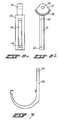
- Figs. 4a, 4b and 4c show a top view, a side view and a front view respectively of a supporting part 20 according to a second embodiment of the bracket unit according to the invention.
- the supporting part 20 has sharply projecting ribs 21, corresponding to the ribs 16 of the first embodiment shown in Fig. 3, on the top side of the supporting part 20 forming a supporting surface.
- the supporting part 20 has flanges 22 which run downwards from the top side (supporting surface) and which run parallel to each other at a distance d, and at one end each have a bore 23 for the passage of a hinge pin (not shown) which runs at right angles to the supporting part 20 and can be formed by a bolt and a nut, which can be accommodated in a polygonal recess 24 in such a way that they cannot turn.
- a bore 25 formed by a slot running in the lengthwise direction of the supporting part 20 is suitable for the passage of a bolt 6 (Fig. 1).
- the bore 25 passes through a chamber 26 which runs in the lengthwise direction of the supporting part 20 and the width of which is greater than the width of the slot 25, and which is suitable for accommodation of a nut, such as a nut 4, in such a way that it can slide and cannot turn therein.
- the chamber or nut nesting space 26 is bounded at one end by a wall 27 and at another end by a projection 28. The nut 4 can be pushed over the projection 28 into the chamber 26, in which process the projection 28 is elastically deformed and subsequent loss of the nut 4 from the chamber 26 is prevented.
- the end of the supporting part 20 at the bores 23 for a hinge pin has between the flanges 22 an insertion space 29 for a coupling part 30 at one end of a bracket part 31, the other, bottom end of which can support therein in clamping fashion a gutter (not shown).
- the coupling part 30 is of a width which is equal to the distance d between the flanges 22 of the supporting part 20 and has a bore 32 for the passage of the hinge pin after the coupling part 30 is inserted into the insertion space 29.
- the bracket part 31 before or after the bracket unit is fastened to the roof 1, the bracket part 31 can be turned into a desired angular position and locked therein, so that the bracket unit can be used in a simple manner for roofs with different slopes. This means that relatively few different parts need to be produced and held in stock, so that the cost of this second embodiment can be relatively low.
- Figs. 6 and 7 show another embodiment of the bracket part 31 shown in Fig. 5 for use with the supporting part 20 shown in Fig. 4.
- the bracket part shown in Figs. 6 and 7 comprises two sub-parts 35, 36, of which the sub-part 35 has a head part 37, like the head part 30 of the bracket part 31 of Fig. 5, with a similar arc part 38 with raised parts and recesses for engaging in the arched part 33 of the supporting part 20, and with a bore 39 for the hinge pin conveyed through the bores 23 of the supporting part 20.
- the sub-part 35 has a slot-type bore 40 which goes through a chamber 41 which is wider than the slot 40.
- the chamber 41 is bounded at one end by a wall 42 and at the other end by a projection 43.
- the chamber 41 can take a nut (not shown) in such a way that it slides and cannot turn therein. This nut can be pushed through an aperture at the projection 43 into the chamber 41, the projection 43 then being elastically deformed, following which loss of the nut from the chamber 41 is prevented.
- a top end of the sub-bracket part 36 has a bore 44 for the passage of a bolt (not shown). After the sub-bracket parts 35 and 36 are placed against each other, said bolt can be screwed via the bore 44 into the nut disposed in the chamber 41, and the sub-part 36 can be tightened with an adjustable distance relative to the head part 37, and thus relative to the corrugated sheet 1.
- a scale division 45 is provided on the outside of a flange of the supporting part 20.
- the bores 12, 15, 25 for the bolt 6 of the supporting part 3, 20 are preferably provided so close to the end of the supporting part 3, 20 where the bracket part 10, 31, 35 is inserted into the supporting part 3, 20 in order to ensure that as strong a fastening as possible of the bracket unit to the eaves section 1 can be obtained, in which the bracket unit, in particular the supporting part 3, will not sag undesirably through the weight of the gutter and the water which it contains, so that damage to the eaves section is avoided.
Landscapes
- Engineering & Computer Science (AREA)
- Architecture (AREA)
- Civil Engineering (AREA)
- Structural Engineering (AREA)
- Roof Covering Using Slabs Or Stiff Sheets (AREA)
- Investigating Or Analysing Materials By The Use Of Chemical Reactions (AREA)
- Transition And Organic Metals Composition Catalysts For Addition Polymerization (AREA)
- Building Awnings And Sunshades (AREA)
- Fittings On The Vehicle Exterior For Carrying Loads, And Devices For Holding Or Mounting Articles (AREA)
- Load-Engaging Elements For Cranes (AREA)
- Rear-View Mirror Devices That Are Mounted On The Exterior Of The Vehicle (AREA)
- Mutual Connection Of Rods And Tubes (AREA)
- Supports For Pipes And Cables (AREA)
Claims (10)
ein längliches Tragteil (3) mit einer Tragfläche zum Eingriff mit der Unterseite des Dachrandes (1), einem länglichen Halteteilaufnahmeraum (8), der in Längsrichtung des Tragteils (3) verläuft und an einem Ende von ihm (8) eine Halteteileinsetzöffnung hat, und mit einer Schraubenaufnahmebohrung (12, 15; 25), die senkrecht durch die Tragfläche verläuft;
ein Halteteil (10) mit einem länglichen oberen Ende (9), das in den Halteteilaufnahmeraum (8) des Tragteils (3) einsetzbar ist, und einem unteren gebogenen Ende zum Tragen der Dachrinne;
eine Befestigungseinrichtung, umfassend eine Schraube (6) zum Einsetzen in die Schraubenaufnahmebohrung (12, 15) und eine im Dachrand (1) vorgesehene Bohrung und eine Mutter (4); dadurch gekennzeichnet,
daß der Halteteilaufnahmeraum (8) eine Form und Abmessungen zur Aufnahme des oberen Endes des Halteteils (10) in unterschiedlichen Stellungen in Längsrichtung relativ zum Tragteil (3) aufweist,
daß die Schraubenaufnahmebohrung (12, 15) einen in Längsrichtung des Tragteils (3) länglichen Querschnitt hat;
daß das Tragteil (3) einen länglichen Mutteraufnahmeraum (26) innerhalb des Tragteils (3) und die Schraubenaufnahmebohrung (12, 15) umgebend zum Durchführen der Schraube (6) und zur Aufnahme der Mutter (4) aufweist;
daß eine Wand (28) des Mutteraufnahmeraums parallel zur Tragfläche des Tragteils (3) verläuft und zum Durchführen der Mutter (4) in den Mutteraufnahmeraum offen ist;
daß der Halteteilaufnahmeraum (8) durch die Schraubenaufnahmebohrung (12) verläuft;
daß das obere Ende (9) des Halteteils eine Bohrung (11) mit länglichem Querschnitt, die mit der Schraubenaufnahmebohrung (12, 15) des Tragteils (3) durch Verschieben des oberen Endes (9) des Halteteils im Halteaufnahmeraum (8) ausrichtbar ist, aufweist;
daß das obere Ende (9) des Halteteils die offene Wand des Mutteraufnahmeraums zumindest teilweise abdeckt, wenn es in den Halteteilaufnahmeraum (8) eingesetzt ist, um dadurch den Mutteraufnahmeraum im wesentlichen zu schließen, und nach dem Einsetzen des oberen Endes (9) des Halteteils in den Halteteilaufnahmeraum (8) einen Verlust der Mutter(4) daraus zu verhindern; und
daß der Mutteraufnahmeraum (12) Abmessungen aufweist, wodurch die Mutter (4) in Längsrichtung des Tragteils (3) verschiebbar, jedoch nicht um ihre Achse drehbar ist.
ein längliches Tragteil (20) mit einer Tragfläche zum Eingriff mit der Unterseite des Dachrandes (1), einem Halteteilaufnahmeraum (29) und mit einer Schraubenaufnahmebohrung (25), die senkrecht durch die Tragfläche verläuft,
ein Halteteil (31; 35, 36) mit einem oberen Ende (30; 37), das in den Halteteilaufnahmeraum (29) des Tragteils (20) einsetzbar ist, und einem unteren gebogenen Ende zum Tragen der Dachrinne;
eine Befestigungseinrichtung, umfassend eine Schraube (6) zum Einsetzen in die Schraubenaufnahmebohrung (12, 15) und eine im Dachrand (1) vorgesehene Bohrung und eine Mutter (4), dadurch gekennzeichnet,
daß der Halteteilaufnahmeraum (29) eine Form und Abmessungen zur Aufnahme des oberen Endes des Halteteils (10; 31; 35; 36) in unterschiedlichen Stellungen relativ zum Tragteil (20) aufweist;
daß die Schraubenaufnahmebohrung (25) einen in Längsrichtung des Tragteils (20) länglichen Querschnitt hat;
daß das Tragteil (20) einen länglichen Mutteraufnahmeraum (26) innerhalb des Tragteils (20) und die Schraubenaufnahmebohrung (25) umgebend zum Durchführen der Schraube (6) und zur Aufnahme der Mutter (4) aufweist;
daß der Mutteraufnahmeraum (26) eine Einsetzöffnung hat, wobei in der Nähe der Öffnung ein federnder Vorsprung (28) vorgesehen ist, so daß die Mutter (4) über den Vorsprung (28) in den Mutteraufnahmeraum (26) gedrückt werden kann, wobei der Vorsprung (28) elastisch verformt wird, und der Vorsprung (28) danach einen Verlust der Mutter (4) aus dem Mutteraufnahmeraum (26) verhindert; und
daß der Mutteraufnahmeraum (12; 26) Abmessungen aufweist, wodurch die Mutter (4) in Längsrichtung des Tragteils (20) verschiebbar, jedoch nicht um ihre Achse drehbar ist.
daß die Schraubenaufnahmebohrung (12; 25) des Tragteils (3, 20) näher an einem Ende des Tragteils (3; 20), von dem aus das obere Ende (9; 30; 37) des Halteteils (10; 31; 35; 36) in den Halteteilaufnahmeraum (8; 29) einsetzbar ist, als an dem anderen Ende des Tragteils (3; 20) angeordnet ist.
Priority Applications (1)
| Application Number | Priority Date | Filing Date | Title |
|---|---|---|---|
| AT88202589T ATE65819T1 (de) | 1987-11-19 | 1988-11-17 | Halter zum befestigen von dachrinnen. |
Applications Claiming Priority (2)
| Application Number | Priority Date | Filing Date | Title |
|---|---|---|---|
| NL8702770A NL8702770A (nl) | 1987-11-19 | 1987-11-19 | Stelsel voor het bevestigen van een gootbevestigingsbeugel aan een dak. |
| NL8702770 | 1987-11-19 |
Publications (2)
| Publication Number | Publication Date |
|---|---|
| EP0317032A1 EP0317032A1 (de) | 1989-05-24 |
| EP0317032B1 true EP0317032B1 (de) | 1991-07-31 |
Family
ID=19850941
Family Applications (1)
| Application Number | Title | Priority Date | Filing Date |
|---|---|---|---|
| EP88202589A Expired - Lifetime EP0317032B1 (de) | 1987-11-19 | 1988-11-17 | Halter zum Befestigen von Dachrinnen |
Country Status (10)
| Country | Link |
|---|---|
| US (1) | US4940198A (de) |
| EP (1) | EP0317032B1 (de) |
| JP (1) | JPH01163348A (de) |
| AT (1) | ATE65819T1 (de) |
| AU (1) | AU605382B2 (de) |
| CA (1) | CA1307092C (de) |
| DE (1) | DE3864014D1 (de) |
| DK (1) | DK167981B1 (de) |
| NL (1) | NL8702770A (de) |
| NZ (1) | NZ226993A (de) |
Cited By (1)
| Publication number | Priority date | Publication date | Assignee | Title |
|---|---|---|---|---|
| WO2015174831A1 (en) | 2014-05-14 | 2015-11-19 | Jarola Vision B.V. | Device for fixing a gutter to a building construction, building construction with such a device, fixing member, support member |
Families Citing this family (6)
| Publication number | Priority date | Publication date | Assignee | Title |
|---|---|---|---|---|
| GB2231897A (en) * | 1989-05-02 | 1990-11-28 | Novaview Ltd | Gutter mounting assembly |
| AUPR454401A0 (en) * | 2001-04-24 | 2001-05-24 | Poldmaa, Arvo | Ladderlink |
| US7418801B2 (en) * | 2005-04-08 | 2008-09-02 | James Loveless | Standing seam-mounted gutter bracket |
| DE102012224528A1 (de) * | 2012-12-28 | 2014-07-03 | Reisser Schraubentechnik Gmbh | Befestigungskalotte |
| JP6202549B1 (ja) * | 2016-06-24 | 2017-09-27 | 有限会社 広島金具製作所 | 吊り金具 |
| US12546081B2 (en) * | 2023-03-30 | 2026-02-10 | Allan P Henderson | Radial bolt corrugated pipe mold and assembly for cementitious foundations, and method for stabilization |
Family Cites Families (27)
| Publication number | Priority date | Publication date | Assignee | Title |
|---|---|---|---|---|
| DE74506C (de) * | nestler & Breitfeld in Wittigsthal i. S | Mehrtheiliges, verstellbares Dachrinneneisen | ||
| US749419A (en) * | 1904-01-12 | Eaves-protector | ||
| US948901A (en) * | 1910-02-08 | Stephen T Nakashjiam | Raves-trough hanger. | |
| DE376025C (de) * | 1923-05-22 | Paul Wienicke | Eisenduebel zur Befestigung elektrischen Leitungsmaterials | |
| US304425A (en) * | 1884-09-02 | Eaves-trough hanger | ||
| US707941A (en) * | 1902-03-15 | 1902-08-26 | Howard Pope | Eaves-trough hanger. |
| US1017174A (en) * | 1909-04-26 | 1912-02-13 | Valentine Sander | Bracket and support therefor. |
| US972291A (en) * | 1909-09-14 | 1910-10-11 | Frank W Thomas | Spout-hanger. |
| US1384856A (en) * | 1920-08-18 | 1921-07-19 | Berger Brothers Co | Gutter or eaves-trough hanger or support |
| US1478837A (en) * | 1923-03-07 | 1923-12-25 | Rachlin Max | Gutter hanger |
| US1554778A (en) * | 1923-04-14 | 1925-09-22 | Berger Matthew Russell | Eaves-trough shank |
| US1558385A (en) * | 1925-02-20 | 1925-10-20 | Meunier Charles | Gutter mount |
| GB672950A (en) * | 1949-07-27 | 1952-05-28 | Martin Wilesmith | Improvements in or relating to brackets for fixing eaves gutters |
| US3126038A (en) * | 1960-09-02 | 1964-03-24 | jaworski | |
| FR1322199A (fr) * | 1962-02-01 | 1963-03-29 | Support de gouttière | |
| FR1406679A (fr) * | 1964-06-11 | 1965-07-23 | Marais Ets | Support réglable, destiné notamment à fixer des objets au bord de toitures |
| FR1474956A (fr) * | 1966-02-09 | 1967-03-31 | Perfectionnements aux crochets pour supporter des gouttières | |
| DE2061367A1 (de) * | 1969-12-27 | 1972-06-15 | Georg Mez | Vorrichtung zum Halten von Dachrinnen |
| FR2193402A5 (de) * | 1972-07-21 | 1974-02-15 | Theulon Paul | |
| US3809347A (en) * | 1972-10-10 | 1974-05-07 | Aluminum Co Of America | Clip and hanger structure for buildings |
| FR2312683A1 (fr) * | 1975-05-27 | 1976-12-24 | Millardet Sa | Plaquette pour la fixation de plaques de bardage ou de couverture et son procede de fabrication |
| DE2945503A1 (de) * | 1979-11-10 | 1981-05-21 | Wilhelm Bonk | Vorrichtung zum halten von regenrinnen-schellen an gewellten dachplatten |
| BE880052A (nl) * | 1979-11-16 | 1980-03-17 | P V B A Scala Plastics | Middel ter bevestiging van een gootklamp aan een dakplaat. |
| AU8524682A (en) * | 1981-06-11 | 1983-01-04 | J.E. Matthison-Hansen | Roof or wall covering and mounting member for a gutter bracket |
| US4553357A (en) * | 1984-03-08 | 1985-11-19 | Bemis Manufacturing Company | Adjustable rainwater gutter mounting arrangement |
| US4676706A (en) * | 1985-05-15 | 1987-06-30 | Nifco, Inc. | Clip nut |
| GB2176824B (en) * | 1985-06-25 | 1988-06-29 | Hunter Int Ltd | Improvements in or relating to a guttering or pipe support system |
-
1987
- 1987-11-19 NL NL8702770A patent/NL8702770A/nl not_active Application Discontinuation
-
1988
- 1988-11-10 CA CA000582863A patent/CA1307092C/en not_active Expired - Lifetime
- 1988-11-14 US US07/270,001 patent/US4940198A/en not_active Expired - Fee Related
- 1988-11-15 AU AU25130/88A patent/AU605382B2/en not_active Ceased
- 1988-11-16 JP JP63289931A patent/JPH01163348A/ja active Pending
- 1988-11-17 DE DE8888202589T patent/DE3864014D1/de not_active Expired - Lifetime
- 1988-11-17 EP EP88202589A patent/EP0317032B1/de not_active Expired - Lifetime
- 1988-11-17 AT AT88202589T patent/ATE65819T1/de not_active IP Right Cessation
- 1988-11-17 NZ NZ226993A patent/NZ226993A/en unknown
- 1988-11-18 DK DK644988A patent/DK167981B1/da not_active IP Right Cessation
Cited By (1)
| Publication number | Priority date | Publication date | Assignee | Title |
|---|---|---|---|---|
| WO2015174831A1 (en) | 2014-05-14 | 2015-11-19 | Jarola Vision B.V. | Device for fixing a gutter to a building construction, building construction with such a device, fixing member, support member |
Also Published As
| Publication number | Publication date |
|---|---|
| AU605382B2 (en) | 1991-01-10 |
| JPH01163348A (ja) | 1989-06-27 |
| CA1307092C (en) | 1992-09-08 |
| NZ226993A (en) | 1992-01-29 |
| DK644988D0 (da) | 1988-11-18 |
| US4940198A (en) | 1990-07-10 |
| EP0317032A1 (de) | 1989-05-24 |
| DK644988A (da) | 1989-05-20 |
| AU2513088A (en) | 1989-05-25 |
| DE3864014D1 (de) | 1991-09-05 |
| ATE65819T1 (de) | 1991-08-15 |
| NL8702770A (nl) | 1989-06-16 |
| DK167981B1 (da) | 1994-01-10 |
Similar Documents
| Publication | Publication Date | Title |
|---|---|---|
| US6554231B2 (en) | Sprinkler mounting device and method | |
| US4599485A (en) | Electrical receptacle box assembly | |
| US8727582B2 (en) | Recessed lighting fixture with alignment enhancements and methods for mounting same | |
| US4917345A (en) | Adjustable roof curb | |
| US4982476A (en) | Mounting plate for a furniture hinge or the like | |
| US5411310A (en) | Outer support bracket for vehicle sun visor | |
| US5192059A (en) | Fascia board holder | |
| EP0317032B1 (de) | Halter zum Befestigen von Dachrinnen | |
| US5966779A (en) | Base plate for fixing a furniture hinge or the like | |
| US4181293A (en) | Handrail support hardware | |
| GB2111557A (en) | Device for securing a ridge or hip batten to a room structure | |
| US4553357A (en) | Adjustable rainwater gutter mounting arrangement | |
| US5197255A (en) | Anchoring device for fastening cladding panels to a wall | |
| US4601451A (en) | Dual amplifier tap bracket or the like | |
| US4432518A (en) | Eaves trough bracket assembly | |
| CA1141519A (en) | Gutter hanger | |
| DE3704943A1 (de) | Dachpfanne mit halterung und daran befestigtem steigtritt, laufrosthalter oder schneefanggitterhalter | |
| EP0079318B1 (de) | Gepäckträger für Fahrzeuge | |
| US20240116450A1 (en) | Roof rack for a motor vehicle, motor vehicle, and method for producing a roof rack | |
| US4220344A (en) | Lawn mower with vertically adjustable wheels | |
| HU222227B1 (hu) | Tartószerkezet tartozéknak tetőeresz-tartományában való elrendezéséhez | |
| GB2191520A (en) | Wall ties for added walls | |
| EP3994318A1 (de) | Profilbefestigungszubehör und stützsystem mit solch einem profilbefestigungszubehör für verkleidung, erhöhte fussböden, abgehängte decken oder dergleichen | |
| US4352279A (en) | Device for mounting closures on door panels | |
| EP4148338B1 (de) | Kombination aus klammer und profilträger |
Legal Events
| Date | Code | Title | Description |
|---|---|---|---|
| PUAI | Public reference made under article 153(3) epc to a published international application that has entered the european phase |
Free format text: ORIGINAL CODE: 0009012 |
|
| AK | Designated contracting states |
Kind code of ref document: A1 Designated state(s): AT BE CH DE FR GB IT LI LU NL SE |
|
| 17P | Request for examination filed |
Effective date: 19890608 |
|
| 17Q | First examination report despatched |
Effective date: 19900420 |
|
| GRAA | (expected) grant |
Free format text: ORIGINAL CODE: 0009210 |
|
| AK | Designated contracting states |
Kind code of ref document: B1 Designated state(s): AT BE CH DE FR GB IT LI LU NL SE |
|
| REF | Corresponds to: |
Ref document number: 65819 Country of ref document: AT Date of ref document: 19910815 Kind code of ref document: T |
|
| ITF | It: translation for a ep patent filed | ||
| REF | Corresponds to: |
Ref document number: 3864014 Country of ref document: DE Date of ref document: 19910905 |
|
| ET | Fr: translation filed | ||
| PLBE | No opposition filed within time limit |
Free format text: ORIGINAL CODE: 0009261 |
|
| STAA | Information on the status of an ep patent application or granted ep patent |
Free format text: STATUS: NO OPPOSITION FILED WITHIN TIME LIMIT |
|
| 26N | No opposition filed | ||
| EPTA | Lu: last paid annual fee | ||
| EAL | Se: european patent in force in sweden |
Ref document number: 88202589.3 |
|
| PGFP | Annual fee paid to national office [announced via postgrant information from national office to epo] |
Ref country code: LU Payment date: 19961001 Year of fee payment: 9 |
|
| REG | Reference to a national code |
Ref country code: CH Ref legal event code: PUE Owner name: GERRIT JAN DE WILDE TRANSFER- JAROLA DESIGN GMBH |
|
| NLS | Nl: assignments of ep-patents |
Owner name: JAROLA DESIGN GMBH |
|
| REG | Reference to a national code |
Ref country code: GB Ref legal event code: 732E |
|
| REG | Reference to a national code |
Ref country code: FR Ref legal event code: TP |
|
| PG25 | Lapsed in a contracting state [announced via postgrant information from national office to epo] |
Ref country code: LU Free format text: LAPSE BECAUSE OF NON-PAYMENT OF DUE FEES Effective date: 19971117 |
|
| PGFP | Annual fee paid to national office [announced via postgrant information from national office to epo] |
Ref country code: FR Payment date: 19991122 Year of fee payment: 12 Ref country code: CH Payment date: 19991122 Year of fee payment: 12 |
|
| PGFP | Annual fee paid to national office [announced via postgrant information from national office to epo] |
Ref country code: AT Payment date: 19991125 Year of fee payment: 12 Ref country code: GB Payment date: 19991125 Year of fee payment: 12 |
|
| PGFP | Annual fee paid to national office [announced via postgrant information from national office to epo] |
Ref country code: SE Payment date: 19991129 Year of fee payment: 12 |
|
| PG25 | Lapsed in a contracting state [announced via postgrant information from national office to epo] |
Ref country code: AT Free format text: LAPSE BECAUSE OF NON-PAYMENT OF DUE FEES Effective date: 20001117 Ref country code: GB Free format text: LAPSE BECAUSE OF NON-PAYMENT OF DUE FEES Effective date: 20001117 |
|
| PG25 | Lapsed in a contracting state [announced via postgrant information from national office to epo] |
Ref country code: SE Free format text: THE PATENT HAS BEEN ANNULLED BY A DECISION OF A NATIONAL AUTHORITY Effective date: 20001129 |
|
| PG25 | Lapsed in a contracting state [announced via postgrant information from national office to epo] |
Ref country code: LI Free format text: LAPSE BECAUSE OF NON-PAYMENT OF DUE FEES Effective date: 20001130 Ref country code: CH Free format text: LAPSE BECAUSE OF NON-PAYMENT OF DUE FEES Effective date: 20001130 |
|
| GBPC | Gb: european patent ceased through non-payment of renewal fee |
Effective date: 20001117 |
|
| REG | Reference to a national code |
Ref country code: CH Ref legal event code: PL |
|
| EUG | Se: european patent has lapsed |
Ref document number: 88202589.3 |
|
| PG25 | Lapsed in a contracting state [announced via postgrant information from national office to epo] |
Ref country code: FR Free format text: LAPSE BECAUSE OF NON-PAYMENT OF DUE FEES Effective date: 20010731 |
|
| REG | Reference to a national code |
Ref country code: FR Ref legal event code: ST |
|
| NLS | Nl: assignments of ep-patents |
Owner name: WILDKAMP B.V. |
|
| NLS | Nl: assignments of ep-patents |
Owner name: WILDKAMP B.V. |
|
| PG25 | Lapsed in a contracting state [announced via postgrant information from national office to epo] |
Ref country code: IT Free format text: LAPSE BECAUSE OF NON-PAYMENT OF DUE FEES Effective date: 20051117 |
|
| PGFP | Annual fee paid to national office [announced via postgrant information from national office to epo] |
Ref country code: DE Payment date: 20051118 Year of fee payment: 18 |
|
| PG25 | Lapsed in a contracting state [announced via postgrant information from national office to epo] |
Ref country code: DE Free format text: LAPSE BECAUSE OF NON-PAYMENT OF DUE FEES Effective date: 20070601 |
|
| PGFP | Annual fee paid to national office [announced via postgrant information from national office to epo] |
Ref country code: NL Payment date: 20071130 Year of fee payment: 20 |
|
| PGFP | Annual fee paid to national office [announced via postgrant information from national office to epo] |
Ref country code: BE Payment date: 20071128 Year of fee payment: 20 |
|
| BE20 | Be: patent expired |
Owner name: *WILDKAMP B.V. Effective date: 20081117 |
|
| NLV7 | Nl: ceased due to reaching the maximum lifetime of a patent |
Effective date: 20081117 |
|
| PG25 | Lapsed in a contracting state [announced via postgrant information from national office to epo] |
Ref country code: NL Free format text: LAPSE BECAUSE OF EXPIRATION OF PROTECTION Effective date: 20081117 |