EP0316640B1 - Silencieux à basse fréquence - Google Patents
Silencieux à basse fréquence Download PDFInfo
- Publication number
- EP0316640B1 EP0316640B1 EP88117971A EP88117971A EP0316640B1 EP 0316640 B1 EP0316640 B1 EP 0316640B1 EP 88117971 A EP88117971 A EP 88117971A EP 88117971 A EP88117971 A EP 88117971A EP 0316640 B1 EP0316640 B1 EP 0316640B1
- Authority
- EP
- European Patent Office
- Prior art keywords
- feed pipe
- damping
- silencer
- frequency
- flow
- Prior art date
- Legal status (The legal status is an assumption and is not a legal conclusion. Google has not performed a legal analysis and makes no representation as to the accuracy of the status listed.)
- Expired - Lifetime
Links
Images


Classifications
-
- F—MECHANICAL ENGINEERING; LIGHTING; HEATING; WEAPONS; BLASTING
- F01—MACHINES OR ENGINES IN GENERAL; ENGINE PLANTS IN GENERAL; STEAM ENGINES
- F01N—GAS-FLOW SILENCERS OR EXHAUST APPARATUS FOR MACHINES OR ENGINES IN GENERAL; GAS-FLOW SILENCERS OR EXHAUST APPARATUS FOR INTERNAL-COMBUSTION ENGINES
- F01N1/00—Silencing apparatus characterised by method of silencing
Definitions
- the invention is based on a low-frequency silencer according to the preamble of the claim.
- the invention relates to a prior art, as is known from GB-A-888,853.
- a silencer for damping low-frequency sound waves for internal combustion engines is described, the silencer consisting of a feed pipe through which a medium flows and which has a length in the outflow direction from the inlet pipe entry and a row of damping holes distributed over the circumference, via which the flow pipe flows around the circumference Medium flows into the inside of the feed pipe.
- the impedance properties of flow feeds play an important role with regard to their acoustic stability properties, particularly with regard to low-frequency acoustic natural vibrations of such components.
- Sound waves that are emitted into feed divisions should, if possible, not be reflected, or at most only to a small extent. Otherwise, the reflected waves can help to ignite strong resonant vibrations.
- Effective damping of high-frequency sound waves can usually be achieved with simple technical precautions (e.g. using a classic silencer: perforated plate over a small closed cavity). The attenuation of low-frequency sound waves, however, is much more difficult.
- the invention solves the problem of achieving the attenuation of a wide frequency band in the smallest space in a silencer of the type mentioned.
- the main advantage of the invention can be seen in the fact that waves of this type can also be strongly damped, the wavelength of which is substantially greater than four times the length of the feed pipe between the pipe inlet and the row of holes.
- the absorption in the object according to the invention is proportional to the amplitude.
- the damping holes are flowed through.
- the subject matter according to the invention acts as an absorber for the frequency designed in each case, within an attenuation bandwidth of approximately 1 octave.
- silencer can be integrated into all possible turbomachines at any time with only minor modifications due to its simple and space-saving shape, also as a retrofit measure.
- the muffler consists of a feed pipe 1 through which a medium 3 flows and around which a partial medium 4 flows.
- This feed pipe 1 has, after a length L from the pipe entrance, a row of damper bores 2 distributed over the circumference, through which a part 4 of the supplied medium flows into the inside of the feed pipe 1 and collides there with the medium 3 flowing through the feed pipe.
- a medium 5 then leaves the feed pipe 1 and enters a turbomachine, not shown.
- the medium in question is intended to be a gas, in many cases it will be air.
- a wall 6 is intended to symbolize that the feed pipe 1 forming the muffler can communicate directly with a combustion chamber 7 of the turbomachine, not shown.
- the feed pipe 1 can be placed on a premixing element.
- the type of combustion chamber determines whether a change in cross-section, for example due to a jump in the borehole, is required at the transition between feed pipe 1 and the premixing element (not shown) together.
- the feed pipe 1 can be followed directly by a burner, which in turn is connected upstream of the combustion chamber. It is physically noticeable that the feed pipe 1 is only characterized by three geometrical sizes, namely by a cross-sectional area A of the feed pipe 1, by the effective length L of the feed pipe, which extends in the direction of flow from the pipe inlet to the center of the damper bores 2, and not by one shown total cross section B of all damping holes 2 on the bolt circle.
- the total cross-sectional area B of all the damping bores 2 remains for the optimal design of the muffler.
- the number of damping bores 2 distributed over the circumference and their diameter depend on the size of the feed pipe 1. The optimization must take into account that the flow velocity V in the damping bores 2 and the sound velocity c of the medium still play a role as further parameters.
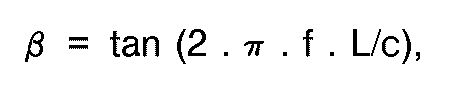
- the sound power of the sound wave of frequency f scattered back by the damper is expressed as a percentage of the radiated power: mean.
- the total cross-sectional area B of the damping holes should be selected so that the parameter ⁇ reaches its optimal value ⁇ OPTIMAL :
- FIG. 2 shows a further embodiment variant of the muffler, in which the air portion 4 is passed to the damping bores 2 through an annular opening 9, which extends over the entire length of the supply pipe 1.
- a second pipe 8 is provided concentrically with the feed pipe 1. The distance between the second pipe 8 and the feed pipe 1 depends on the determined amount of the air portion 4 and also on the desired speed V of the flow through the damping bores 2.
- Fig. 3 shows a graphical representation, from the ⁇ OPTIMAL and the associated percentage performance of the silencer reflected wave are readable.
- the abscissa 10 with the term represents the phase, ie the length of the muffler, which represents the ideal length for the value 1 on the abscissa 10.
- One ordinate 11 plots the power of the wave reflected by the muffler in%, based on the incident wave, ie on the wave which is fanned in the combustion chamber and radiated into the muffler.
- the other ordinate 12 represents ⁇ OPTIMAL . As already explained above, this value contains the total cross-sectional area B of the damping bores 2 as a weight.
- Curve 13 describes the falling power in% of the wave reflected by the muffler as a function of an increasing phase
- the other curve 14 describes the increasing value of ⁇ OPTIMAL with decreasing phase
- the graph clearly shows how the ideal value 1 (ideal length) of the muffler means that the power in% of the wave reflected by the muffler is zero, ie in such a case complete absorption would have been achieved.
Landscapes
- Engineering & Computer Science (AREA)
- Chemical & Material Sciences (AREA)
- Combustion & Propulsion (AREA)
- Mechanical Engineering (AREA)
- General Engineering & Computer Science (AREA)
- Exhaust Silencers (AREA)
- Structures Of Non-Positive Displacement Pumps (AREA)
Claims (1)
- Pot d'échappement pour l'amortissement d'ondes sonores à basse fréquence,a) qui présente essentiellement un tube d'arrivée (1),b) lequel présente, à une distance prédéterminée (L) à partir de l'entrée du tube d'arrivée dans le sens de circulation, plusieurs orifices d'amortissement (2) répartis sur le pourtour du tube d'arrivée, à travers lesquels un fluide (4) circulant autour du tube d'arrivée (1) peut pénétrer à l'intérieur du tube d'arrivée,
caractérisé en ce quec) les orifices d'amortissement (2) présentent une section totale (B) de:

où:
A = section prédéterminable du tube d'arrivée (1),
c = vitesse du son dans le fluide,
f = fréquence de l'onde sonore, et
V = vitesse d'écoulement à travers les orifices d'amortissement (2).
Applications Claiming Priority (2)
| Application Number | Priority Date | Filing Date | Title |
|---|---|---|---|
| CH449487 | 1987-11-18 | ||
| CH4494/87 | 1987-11-18 |
Publications (2)
| Publication Number | Publication Date |
|---|---|
| EP0316640A1 EP0316640A1 (fr) | 1989-05-24 |
| EP0316640B1 true EP0316640B1 (fr) | 1993-02-10 |
Family
ID=4277151
Family Applications (1)
| Application Number | Title | Priority Date | Filing Date |
|---|---|---|---|
| EP88117971A Expired - Lifetime EP0316640B1 (fr) | 1987-11-18 | 1988-10-28 | Silencieux à basse fréquence |
Country Status (3)
| Country | Link |
|---|---|
| US (1) | US4923035A (fr) |
| EP (1) | EP0316640B1 (fr) |
| DE (1) | DE3878408D1 (fr) |
Cited By (1)
| Publication number | Priority date | Publication date | Assignee | Title |
|---|---|---|---|---|
| EP3034666A1 (fr) | 2014-12-17 | 2016-06-22 | Fraunhofer-Gesellschaft zur Förderung der angewandten Forschung e.V. | Tissu isolant et filtrant et son utilisation en tant que materiau inerte absorbant le bruit |
Families Citing this family (5)
| Publication number | Priority date | Publication date | Assignee | Title |
|---|---|---|---|---|
| JP3863588B2 (ja) * | 1995-04-29 | 2006-12-27 | 株式会社大宇エレクトロニクス | 洗濯機用気泡発生器 |
| US20040163886A1 (en) * | 2002-02-15 | 2004-08-26 | Sutera Anthony J. | Air turbine for combustion engine |
| US6619276B1 (en) * | 2002-08-28 | 2003-09-16 | General Motors Corporation | Positive crankcase ventilation orifice muffler |
| US7650965B2 (en) * | 2006-06-09 | 2010-01-26 | Emcon Technologies Llc | Exhaust system |
| US9422843B2 (en) * | 2013-09-08 | 2016-08-23 | Michael Wayne Barrett | Resonance generating muffler |
Family Cites Families (9)
| Publication number | Priority date | Publication date | Assignee | Title |
|---|---|---|---|---|
| US944646A (en) * | 1909-02-18 | 1909-12-28 | Joseph A Xardell | Exhaust-muffler. |
| US1338520A (en) * | 1919-07-03 | 1920-04-27 | George W Moores | Muffler |
| US1966620A (en) * | 1932-11-26 | 1934-07-17 | Fluor Corp | Muffler |
| US2838128A (en) * | 1955-08-30 | 1958-06-10 | Sr Edward A Kliewer | Engine exhaust muffler |
| GB888853A (en) * | 1958-12-30 | 1962-02-07 | Edward Henry Phillips | Exhaust silencer |
| DE1264864B (de) * | 1960-06-27 | 1968-03-28 | Leistritz Hans Karl | Schalldaempfer fuer stroemende Gase |
| US3361227A (en) * | 1963-10-24 | 1968-01-02 | Mekes Oy | Mufflers and exhaust systems |
| US3888331A (en) * | 1974-05-03 | 1975-06-10 | Gen Motors Corp | Power tuned wave interference silencer |
| MX145535A (es) * | 1976-08-31 | 1982-03-03 | Nihon Radiator Co | Mejoras a silenciador de escape para motores de combustion interna |
-
1988
- 1988-10-28 EP EP88117971A patent/EP0316640B1/fr not_active Expired - Lifetime
- 1988-10-28 DE DE8888117971T patent/DE3878408D1/de not_active Expired - Lifetime
- 1988-11-10 US US07/269,313 patent/US4923035A/en not_active Expired - Lifetime
Cited By (2)
| Publication number | Priority date | Publication date | Assignee | Title |
|---|---|---|---|---|
| EP3034666A1 (fr) | 2014-12-17 | 2016-06-22 | Fraunhofer-Gesellschaft zur Förderung der angewandten Forschung e.V. | Tissu isolant et filtrant et son utilisation en tant que materiau inerte absorbant le bruit |
| DE102014226266A1 (de) | 2014-12-17 | 2016-06-23 | Fraunhofer-Gesellschaft zur Förderung der angewandten Forschung e.V. | Dämm- und Filterstoff und seine Verwendung als inertes schallabsorbierendes Material |
Also Published As
| Publication number | Publication date |
|---|---|
| DE3878408D1 (de) | 1993-03-25 |
| EP0316640A1 (fr) | 1989-05-24 |
| US4923035A (en) | 1990-05-08 |
Similar Documents
| Publication | Publication Date | Title |
|---|---|---|
| DE69838047T2 (de) | Kompaktes Messgerät zur Messung der Gasströmung bei variablem Druck | |
| DE60302140T2 (de) | Schalldämfungseinrichtung für ein strömungssystem | |
| EP1832812A2 (fr) | Paroi de chambre de combustion de turbine à gaz avec amortissement des vibrations de la chambre de combustion | |
| DE19948674B4 (de) | Verbrennungseinrichtung, insbesondere für den Antrieb von Gasturbinen | |
| WO2010018069A1 (fr) | Procédé pour régler un résonateur de helmholtz et résonateur de helmholtz destiné à mettre en œuvre le procédé | |
| DE2858092C2 (de) | Anordnung zur Messung des Strömungsmitteldurchsatzes durch eine Leitung | |
| DE19851636A1 (de) | Dämpfungsvorrichtung zur Reduzierung der Schwingungsamplitude akustischer Wellen für einen Brenner | |
| EP2394033A1 (fr) | Silencieux présentant des éléments encastrés hélicoïdaux | |
| DE2712326C2 (de) | Brenner | |
| EP0316640B1 (fr) | Silencieux à basse fréquence | |
| EP0580099A2 (fr) | Compteur de gaz à ultrasons | |
| DE19701533A1 (de) | Füllstandsmeßsystem | |
| EP0990851B1 (fr) | Chambre de combustion pour une turbine à gaz | |
| DE2545364C3 (fr) | ||
| DE68923212T2 (de) | Integrierte Mehrzweck-Entspannungsstation zum Versorgen eines sekundären Gasnetzes. | |
| DE2007046C3 (de) | Pulsationsdämpfer zum Dämpfen der in einer Rohrleitungsanordnung auftretenden Strömungsmitteldruckpulsationen | |
| DE2706957A1 (de) | Abgasschalldaempfer fuer brennkraftmaschinen mit von der abgasleitung abzweigendem resonator | |
| CH635171A5 (de) | Einrichtung an einem diffusor zum unterdruecken von resonanzen. | |
| DE10035241B4 (de) | Durchflußmesser | |
| DE1067652B (de) | Druck-Reduzierventil zur geraeusch- und vibrationsarmen Drosselung stroemender gasfoermiger Medien, insbesondere zur Druckreduzierung von Dampf | |
| EP0821823B1 (fr) | Silencieux pour ondes ultrasonores | |
| DE2402902A1 (de) | Schalldaempfung von fluidleitungen | |
| DE602004007163T2 (de) | Verfahren zur reduzierung von lärm eines hochleistungs-verbrennungsmotors | |
| EP1510668B1 (fr) | Silencieux et dispositif d'échappement | |
| EP1918642A2 (fr) | Dispositif de chambre de combustion |
Legal Events
| Date | Code | Title | Description |
|---|---|---|---|
| PUAI | Public reference made under article 153(3) epc to a published international application that has entered the european phase |
Free format text: ORIGINAL CODE: 0009012 |
|
| AK | Designated contracting states |
Kind code of ref document: A1 Designated state(s): CH DE GB LI NL |
|
| 17P | Request for examination filed |
Effective date: 19891110 |
|
| 17Q | First examination report despatched |
Effective date: 19910402 |
|
| GRAA | (expected) grant |
Free format text: ORIGINAL CODE: 0009210 |
|
| AK | Designated contracting states |
Kind code of ref document: B1 Designated state(s): CH DE GB LI NL |
|
| REF | Corresponds to: |
Ref document number: 3878408 Country of ref document: DE Date of ref document: 19930325 |
|
| GBT | Gb: translation of ep patent filed (gb section 77(6)(a)/1977) |
Effective date: 19930416 |
|
| PG25 | Lapsed in a contracting state [announced via postgrant information from national office to epo] |
Ref country code: LI Effective date: 19931031 Ref country code: CH Effective date: 19931031 |
|
| PGFP | Annual fee paid to national office [announced via postgrant information from national office to epo] |
Ref country code: NL Payment date: 19931031 Year of fee payment: 6 |
|
| PLBE | No opposition filed within time limit |
Free format text: ORIGINAL CODE: 0009261 |
|
| STAA | Information on the status of an ep patent application or granted ep patent |
Free format text: STATUS: NO OPPOSITION FILED WITHIN TIME LIMIT |
|
| 26N | No opposition filed | ||
| REG | Reference to a national code |
Ref country code: CH Ref legal event code: PL |
|
| PG25 | Lapsed in a contracting state [announced via postgrant information from national office to epo] |
Ref country code: NL Effective date: 19950501 |
|
| NLV4 | Nl: lapsed or anulled due to non-payment of the annual fee | ||
| PGFP | Annual fee paid to national office [announced via postgrant information from national office to epo] |
Ref country code: GB Payment date: 19970915 Year of fee payment: 10 |
|
| PG25 | Lapsed in a contracting state [announced via postgrant information from national office to epo] |
Ref country code: GB Free format text: LAPSE BECAUSE OF NON-PAYMENT OF DUE FEES Effective date: 19981028 |
|
| GBPC | Gb: european patent ceased through non-payment of renewal fee |
Effective date: 19981028 |
|
| PGFP | Annual fee paid to national office [announced via postgrant information from national office to epo] |
Ref country code: DE Payment date: 20071025 Year of fee payment: 20 |