EP0314876B1 - Apparatus for applying anti-sticking agent on annealed oriented electrical sheet steel in coil - Google Patents
Apparatus for applying anti-sticking agent on annealed oriented electrical sheet steel in coil Download PDFInfo
- Publication number
- EP0314876B1 EP0314876B1 EP88110712A EP88110712A EP0314876B1 EP 0314876 B1 EP0314876 B1 EP 0314876B1 EP 88110712 A EP88110712 A EP 88110712A EP 88110712 A EP88110712 A EP 88110712A EP 0314876 B1 EP0314876 B1 EP 0314876B1
- Authority
- EP
- European Patent Office
- Prior art keywords
- coiler
- movable
- coil
- movable frame
- hood
- Prior art date
- Legal status (The legal status is an assumption and is not a legal conclusion. Google has not performed a legal analysis and makes no representation as to the accuracy of the status listed.)
- Expired
Links
Images


Classifications
-
- C—CHEMISTRY; METALLURGY
- C21—METALLURGY OF IRON
- C21D—MODIFYING THE PHYSICAL STRUCTURE OF FERROUS METALS; GENERAL DEVICES FOR HEAT TREATMENT OF FERROUS OR NON-FERROUS METALS OR ALLOYS; MAKING METAL MALLEABLE, e.g. BY DECARBURISATION OR TEMPERING
- C21D1/00—General methods or devices for heat treatment, e.g. annealing, hardening, quenching or tempering
- C21D1/68—Temporary coatings or embedding materials applied before or during heat treatment
- C21D1/70—Temporary coatings or embedding materials applied before or during heat treatment while heating or quenching
-
- C—CHEMISTRY; METALLURGY
- C23—COATING METALLIC MATERIAL; COATING MATERIAL WITH METALLIC MATERIAL; CHEMICAL SURFACE TREATMENT; DIFFUSION TREATMENT OF METALLIC MATERIAL; COATING BY VACUUM EVAPORATION, BY SPUTTERING, BY ION IMPLANTATION OR BY CHEMICAL VAPOUR DEPOSITION, IN GENERAL; INHIBITING CORROSION OF METALLIC MATERIAL OR INCRUSTATION IN GENERAL
- C23C—COATING METALLIC MATERIAL; COATING MATERIAL WITH METALLIC MATERIAL; SURFACE TREATMENT OF METALLIC MATERIAL BY DIFFUSION INTO THE SURFACE, BY CHEMICAL CONVERSION OR SUBSTITUTION; COATING BY VACUUM EVAPORATION, BY SPUTTERING, BY ION IMPLANTATION OR BY CHEMICAL VAPOUR DEPOSITION, IN GENERAL
- C23C24/00—Coating starting from inorganic powder
Definitions
- This invention relates to an apparatus for electrostatically applying an anti-sticking agent on annealed oriented electrical sheet steel in coil.
- Oriented electrical sheet steel made from hot-rolled strip by applying one, two or more cold reduction and annealing processes is further subjected, in coil form, to annealing at elevated temperatures to develop the crystals in (110) and [001] orientations.
- the strip to undergo this elevated-temperature annealing is coiled after an anti-sticking agent is applied on the exit side of the continuous annealing furnace to prevent the occurrence of undesirable seizure between individual wraps of the coil.
- Magnesia, alumina and some other refractories have been used as the anti-sticking agent. Aqueous suspensions of such refractories are applied and dried on the surface of the strip. Especially magnesia has been in popular use as it forms a glassy film consisting essentially of forsterite (2MgO ⁇ SiO2) reacting at high temperatures with a layer of scale, consisting principally of silica, formed on the surface of the strip.
- magnesia When magnesia is suspended in water, part of it is hydrated into magnesium hydroxide, which, in the subsequent annealing process, gets decomposed and excessively oxidizes the surface of the strip, thereby damaging the magnetic properties of the steel and the uniformity of the glassy film.
- the methods disclosed in the Japanese Patent Public Disclosure Nos. 12211 of 1964 and 11393 of 1982 electrostatically apply powders of anti-sticking agent on the surface of steel strip to be annealed.
- the method of the Japanese Patent Public Disclosure No. 12211 of 1964 applies a powder of anti-sticking agent on the surface of steel strip by introducing the powder into a space between the strip and an electrode discharging a positive corona.
- the method of the Japanese Patent Public Disclosure No. 11393 of 1982 applies a small quantity of slurry consisting principally of magnesium oxide on the surface of strip in order to assure the forming of a good glassy film. Then, an electrically charged powder of anti-sticking agent is applied on the dried undercoat on the oppositely charged strip of oriented electrical steel.
- the object of this invention is to provide means for electrostatically applying a powder of anti-sticking agent on strip of oriented electrical steel that is capable of efficient powder application and effective dust collection.
- An apparatus for applying a powder of anti-sticking agent on a coil of oriented electrical sheet steel provided next to a coiler comprises (a) an assembly capable of moving close to and away from the coiler, (b) a stationary hood attached to the movable assembly and having slit-like suction ports opening on the coiler side provided along the walls thereof, (c) a dust-collecting duct connected to the slit-like suction ports of the stationary hood, (d) movable hoods attached to the stationary hood and adapted to move up and down at the top and bottom of the open end of the stationary hood, (e) a group of electro-static spray guns provided in the stationary hood and directed toward the coiler, and (f) drive units that move the movable assembly away from the coiler and open the movable hoods as the diameter of a coil of electrical steel strip on the coiler increases.
- the group of electrostatic spray guns are moved backward so that they are always away from the coil at a distance appropriate for the application of the anti-sticking agent.
- the movalbe hoods are adjusted so that a given small clearance is always kept between the surface of the strip and the edge of the movable hoods.
- the slit-like suction ports provided along the walls of the stationary hood, do not draw out the powder of the anti-sticking agent flying from the elec-trostatic spray guns to the surface of the strip.
- the slit-like suction ports draw out only such powder as have reached the surface of the strip but have failed to adhere thereto or bounced thereoff. Such powder will escape to the outside of the hoods (both stationary and movable) through said small clearance if it were not for the slit-like suction ports.
- the provision of the slit-like suction ports prevents the undesirable outflow of the anti-sticking agent that may cause a serious environmental pollution problem.
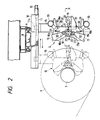
- Fig. 1 shows an apparatus for applying anti-sticking agent on annealed oriented electrical sheet steel in coil of this invention, together with a coiler.
- a coiler 3 winds up strip of oriented electrical steel S, which has passed through a bridle 1 and over a deflector roll 2 and is to be applied with a powder of anti-sticking agent, into a coil 4.
- the bridle 1 provides an appropriate amount of tension to the strip S to be wound up by the coiler 3.
- a belt wrapper 5 is disposed downstream in such a manner as to face the coiler 3. The belt wrapper 5 wraps the leading end of the strip S around the mandrel of the coiler 3 before starting the winding of the coil 4.
- the anti-sticking agent application apparatus is provided at the right of the coiler 3 in the figure.
- This apparatus consists essentially of a retracting mechanism A to bring the whole apparatus into and out of the application line, a mechanism B to move a gun-hood assembly G back and forth according to a change in the diameter of the coil 4, a mechanism C to open and close movalbe hoods according to the same change in the coil diameter, a dust-collecting mechanism D comprising a hood with slit-like suction ports, and an electrostatic powder application unit E.
- the gun-hood assembly G comprises a movable assembly in form of frame 15 and the movable hoods open-close mechanism C, dust-collecting mechanism D and electrostatic powder application unit E mounted on the movable frame 15.
- the retracting mechanism A comprises rollers 7 running along rails 6 attached to the ceiling to extend parallel to the mandrel of the coiler 3.
- the rollers 7 carry a traverser 8 that is driven by a hydraulic cylinder 9.
- a beam 10 extending at right angles to the axis of the coiler 3 is attached to the traverser 8.
- the movable frame 15 suspends from the beam 10.
- the movable frame 15, i.e., the gun-hood assembly G moves toward and away from the coiler 3 by means of a screw 11 to adjust the space between itself and the coil 4 as shown in Fig. 2.
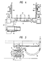
- the reciprocating mechanism B to move the gun-hood assembly G according to a change in the diameter of the coil 4 comprises the screw 11 rotatably fitted in the beam 10 as shown in Figs. 1, 2 and 5.
- An AC servo motor 12 is connected to the rear end of the screw 11.
- An internally threaded slider 11a is fitted over the screw 11.
- the movable frame 15 hangs from the slider 11a.
- the AC servo motor 12 turns the screw 11, thereby moving back and forth the movable frame 15.
- a control unit 14 controls the operation of the AC servo motor 12 on the basis of the diameter of the coil 4 that is derived from the ratio between the numbers of rotations of the bridle 1 and coiler 3 determined by pulse generators 13a and 13b, known strip thickness and other data.
- the control unit 14 contains a general-purpose microcomputer of the known type that performs the above computation and outputs an operational signal to the AC servo motor 12.
- the mechanism C to open and close, according to a change in the coil diameter, top and bottom movable hoods 16 and 17 provided on the outside of a stationary hood 18, as shown in Figs. 1, 2 and 3, comprises an AC servo motor 19 mounted on the movable frame 15 at the back of the stationary hood 18 as shown in Figs. 1, 2 and 4.
- the rotation of the AC servo motor 19 is transmitted to a rotating shaft 21 by means of a belt 20.
- An internally threaded slider 23 having racks 24 cut at the top and bottom ends thereof is fitted over a threaded portion 22 at the front end of the rotating shaft 21 as shown in Fig. 2.
- Guided by linear-motion guides 25, the slider 23 moves back and forth with the rotating shaft 2l as the rotating shaft 21 rotates.
- Reference characters 16a and 17a designate pinions engaged with the racks 24.
- the movable hoods 16 and 17 are attached to the pinions 16a and 17a.
- the AC servo motor 19 opens and closes the top and bottom movable hoods 16 and 17.
- the control unit 14 controls the operation of the AC servo motor 19, in the same way as with the AC servo motor 12, to adjust the opening of the movable hoods 16 and 17 on the basis of a change in the diameter of the coil 4, as shown in Fig. 1.
- a dot-dash line in Fig. 2 shows the gun-hood assembly G brought closer to the coiler 3.
- the dust-collecting mechanism D comprises a stationary hood 18 having slit-like suction ports.
- the stationary hood 18 is defined by top and bottom walls 18a and 18b, side walls 18c and 18d, and a rear wall 18e, as shown in Figs. 1 to 4.
- Each of the side walls 18c and 18d has a double structure 26 as shown in Figs. 3 and 4.
- the front end (i.e., the end facing the coil 4) of the double-structure side walls 18c and 18d is opened to form a slit-like suction port 27.
- the front edge of the stationary hood 18 curves substantially in conformity with the curved profile of the mandrel of the coiler 3.
- Movable plates 28 and 29 extending across the width of the stationary hood 18 are provided below the top wall 18a and above the bottom wall 18b, respectively, as shown in Figs. 2 and 3. As illustrated, the rear end of the movable plates 28 and 29 is rotatable on a pivot 30. The movable plates 28 and 29 turn as a pin 31 attached thereto is moved along a guide slot 32. A space between the top wall 18a and movable plate 28 and a space between the bottom wall 18b and movable plate 29 form slit-like suction ports 33. The open area of the slit-like suction ports 33 is adjusted by turning the movable plates 28 and 29. Fine adjustment of the sucking force of the suction ports 33 can be achieved by the adjustment of the open area thereof.
- the suction ports 33 may be of the structure analogous to that of the suction ports 27.
- the movable hoods 16 and 17 are pivotally supported by the side walls 18c and 18d so as to be movable back and forth.
- reference numeral 34 designates an exit port from which powder of magnesia sucked through the suction ports 33 is discharged outside
- reference numeral 35 denotes another exit port from which powder of magnesia sucked through the suction ports 27 is discharged outside.
- the exit ports 34 and 35 are connected to a common exhaust duct 36.
- Reference numeral 38 designates a flexible exhaust hose. The flexible hose 38 is connected to an exhaust fan (not shown).
- Electrostatic powder application unit E is
- the electrostatic powder application unit E comprising a total of eight electrostatic spray guns 37, four disposed on top of four, is inserted into the stationary hood 18 through the rear wall 18e thereof.
- a powder feeder (not shown) supplies powder of magnesia under pressure, which is an anti-sticking agent, to the electrostatic spray guns 37.
- the tip of the spray guns 37 discharge electric coronas, whereby the powder of magnesia is charged when the powder passes through such coronas.
- the charged powder of magnesia reaches and adheres to the surface of the strip.
- the hydraulic cylinder 9 is operated to retract the gun-hood assembly G out of the powder application line.
- the belt wrapper 5 is brought closer to the coiler 3 by means of the hydraulic cylinder 5a. With the help of the belt wrapper 5, the leading end of the electrical steel strip S is wrapped around the coiler 3 by the known method.
- the hydraulic cylinder 5a is operated again to withdraw the belt wrapper 5.
- the hydraulic cylinder is operated again to push the gun hood assembly G into the powder application line.
- the gun-hood assembly G is moved closer to the coiler 3, as indicated by the dot-dash line in Fig 2, so that a given space is maintained between the coiler 3 and the electrostatic spray guns 37.
- the portion of the coil on which the powder of anti-sticking agent is to be applied is covered by the stationary hood 18.
- the AC servo motor 19 is operated to close the movable hoods 16 and 17 until a given small space is left between the movable hoods 16 and 17 and the coiler 3.
- the electrostatic spray guns 37 in conjunction with a dust-collector (not shown), states the electrostatic application of the magnesia powder onto the surface of the coil 4.
- the control unit 14 shown in Fig. 1 controls the operation of the AC servo motors 12 and 19 to withdraw the gun-hood assembly G and open the movable hoods 16 and 17 as the diameter of the coil 4 increases so that the given space between the coil 4 and the spray guns 37 is always maintained.
- the charged powder of magnesia ejected from the spray guns 37 adhere to the surface of the oppositely charged coil 4. Such powder as has failed to adhere is sucked away by the slit-like suction ports 33 at the top and bottom and the slit-like suction ports 27 on both sides and then discharged outside through the exhaust duct 36.
- a feature of this invention lies in the combination of the stationary hood 18 with the movable hoods 16 and 17.
- Another feature of this invention lies in the dust-collecting mechanism having the slit-like suction ports 27 and 33.
- the common method to collect dust from the whole area within the hood will catch not only unwanted dust but also the magnesia powder flying from the electrostatic spray guns to the coil, thereby seriously impairing the powder application efficiency.
- the dust-collecting mechanism of our invention is based on an idea to achieve a remarkable increase in the powder application efficiency by collecting only such portion of the magnesia powder as is about to flow out through the small space between the coil and the hood.
- unwanted dust is drawn out through the slit-like suction ports 27 and 33 provided along the stationary hood surrounding the electrostatic spray guns.
- the magnesia powder flying from the guns to the coil remains unaffected by the suction force.
- the slit-like suction ports 33 at the top and bottom of the stationary hood also may be designed like the double structure 26 of the side walls 18c and 18d.
- the slit-like suction ports 27 provided along the side walls 18c and 18d also may be designed to be capable of adjusting the area of opening like the top and bottom slit-like suction ports 33. If the coiler 3 is of the type having no belt wrapper 5, the retracting mechanism A to bring the whole apparatus in and out of the application line may be omitted.
Landscapes
- Chemical & Material Sciences (AREA)
- Engineering & Computer Science (AREA)
- Materials Engineering (AREA)
- Mechanical Engineering (AREA)
- Metallurgy (AREA)
- Organic Chemistry (AREA)
- Thermal Sciences (AREA)
- Crystallography & Structural Chemistry (AREA)
- Physics & Mathematics (AREA)
- Chemical Kinetics & Catalysis (AREA)
- Chemical Treatment Of Metals (AREA)
- Manufacturing Of Steel Electrode Plates (AREA)
- Heat Treatment Of Sheet Steel (AREA)
- Winding, Rewinding, Material Storage Devices (AREA)
- Electrostatic Spraying Apparatus (AREA)
Applications Claiming Priority (2)
| Application Number | Priority Date | Filing Date | Title |
|---|---|---|---|
| JP62278311A JPH01123033A (ja) | 1987-11-05 | 1987-11-05 | 方向性電磁鋼帯コイルへの焼鈍分離剤塗布装置 |
| JP278311/87 | 1987-11-05 |
Publications (2)
| Publication Number | Publication Date |
|---|---|
| EP0314876A1 EP0314876A1 (en) | 1989-05-10 |
| EP0314876B1 true EP0314876B1 (en) | 1991-11-27 |
Family
ID=17595569
Family Applications (1)
| Application Number | Title | Priority Date | Filing Date |
|---|---|---|---|
| EP88110712A Expired EP0314876B1 (en) | 1987-11-05 | 1988-07-05 | Apparatus for applying anti-sticking agent on annealed oriented electrical sheet steel in coil |
Country Status (4)
| Country | Link |
|---|---|
| US (1) | US4825807A (enExample) |
| EP (1) | EP0314876B1 (enExample) |
| JP (1) | JPH01123033A (enExample) |
| DE (1) | DE3866512D1 (enExample) |
Families Citing this family (14)
| Publication number | Priority date | Publication date | Assignee | Title |
|---|---|---|---|---|
| US5107789A (en) * | 1989-02-01 | 1992-04-28 | Blodgett & Blodgett, P.C. | Article coating system |
| US5259879A (en) * | 1991-06-27 | 1993-11-09 | Ransburg Corporation | Powder application booth liner and method of making it |
| US6889921B2 (en) * | 2002-09-30 | 2005-05-10 | Illinois Tool Works Inc. | Bell cup skirt |
| US20050023385A1 (en) * | 2003-07-29 | 2005-02-03 | Kui-Chiu Kwok | Powder robot gun |
| US7128277B2 (en) * | 2003-07-29 | 2006-10-31 | Illinois Tool Works Inc. | Powder bell with secondary charging electrode |
| US20050056212A1 (en) * | 2003-09-15 | 2005-03-17 | Schaupp John F. | Split shroud for coating dispensing equipment |
| US20050173556A1 (en) * | 2004-02-09 | 2005-08-11 | Kui-Chiu Kwok | Coating dispensing nozzle |
| US8371517B2 (en) * | 2007-06-29 | 2013-02-12 | Illinois Tool Works Inc. | Powder gun deflector |
| US20090020626A1 (en) * | 2007-07-16 | 2009-01-22 | Illinois Tool Works Inc. | Shaping air and bell cup combination |
| US10155233B2 (en) * | 2008-04-09 | 2018-12-18 | Carlisle Fluid Technologies, Inc. | Splash plate retention method and apparatus |
| KR101256495B1 (ko) * | 2010-06-15 | 2013-04-19 | 최규종 | 판넬 측면상도장치 |
| WO2016012858A1 (en) * | 2014-07-24 | 2016-01-28 | Sabic Global Technologies B.V. | Annealed cold rolled steel and method for preparing same |
| CN114191911A (zh) * | 2021-11-15 | 2022-03-18 | 安徽华裕重工有限公司 | 一种发电厂炉渣处理用降尘喷淋设备 |
| CN120038219B (zh) * | 2025-04-27 | 2025-07-08 | 宁波韵升弹性元件有限公司 | 一种钢带卷绕设备及其卷绕成型方法 |
Family Cites Families (9)
| Publication number | Priority date | Publication date | Assignee | Title |
|---|---|---|---|---|
| US2165635A (en) * | 1937-10-27 | 1939-07-11 | James O Keighley | Method of treating cold-rolled metals |
| US3000752A (en) * | 1957-12-30 | 1961-09-19 | Armco Steel Corp | Coating metallic sheet or strip material with powdered annealing separator substances |
| US3181846A (en) * | 1963-04-05 | 1965-05-04 | United States Steel Corp | Method and apparatus for open coil annealing |
| LU67358A1 (enExample) * | 1973-04-04 | 1974-05-09 | ||
| US4088093A (en) * | 1976-04-13 | 1978-05-09 | Continental Can Company, Inc. | Web coating and powder feed |
| JPS5711393A (en) * | 1980-06-25 | 1982-01-21 | Tokyo Electric Co Ltd | Remote display unit |
| US4488505A (en) * | 1981-07-15 | 1984-12-18 | Schaming Industries, Inc. | Electronic strip oiler |
| JPS6014105B2 (ja) * | 1982-10-07 | 1985-04-11 | 新日本製鐵株式会社 | 方向性電磁鋼板の焼鈍分離剤塗布方法 |
| JPS60128213A (ja) * | 1983-12-14 | 1985-07-09 | Nippon Steel Corp | 方向性電磁鋼帯への焼鈍分離剤塗布方法 |
-
1987
- 1987-11-05 JP JP62278311A patent/JPH01123033A/ja active Granted
-
1988
- 1988-07-05 DE DE8888110712T patent/DE3866512D1/de not_active Expired - Lifetime
- 1988-07-05 EP EP88110712A patent/EP0314876B1/en not_active Expired
- 1988-07-13 US US07/218,300 patent/US4825807A/en not_active Expired - Fee Related
Also Published As
| Publication number | Publication date |
|---|---|
| JPH01123033A (ja) | 1989-05-16 |
| DE3866512D1 (de) | 1992-01-09 |
| JPH0377875B2 (enExample) | 1991-12-11 |
| US4825807A (en) | 1989-05-02 |
| EP0314876A1 (en) | 1989-05-10 |
Similar Documents
| Publication | Publication Date | Title |
|---|---|---|
| EP0314876B1 (en) | Apparatus for applying anti-sticking agent on annealed oriented electrical sheet steel in coil | |
| EP0183135B2 (en) | Automatic cutting and winding apparatus for a web-like material such as a film | |
| EP0697007B1 (en) | Web transfer mechanism and method for a continuous winder | |
| CN114408646B (zh) | 一种高速uv涂布机 | |
| US20020179769A1 (en) | Winding device, and method for performing a winding shaft change in a winding device | |
| CN109898067A (zh) | 一种柔性基材双面卷绕镀膜自动生产线 | |
| JPS59139505A (ja) | ケ−ブル仕上装置 | |
| CN113928926A (zh) | 一种电线电缆绕线设备 | |
| CN105947769A (zh) | 自动包装膜分切机 | |
| EP1015147B1 (en) | High speed transfer of strip in a continuous strip processing application | |
| JPH038543A (ja) | 巻取リールに金属ストリップを巻き取るための押付けおよび切離し装置 | |
| CN113816203A (zh) | 一种料带收料设备 | |
| CN218289815U (zh) | 一种布料加工用收卷机 | |
| EP0648554A1 (en) | A method and apparatus for inserting a paper strip in a metallic strip continuous processing line | |
| JP3135677B2 (ja) | 間紙連続供給方法 | |
| CN212270229U (zh) | 一种隧道式不锈钢装饰卷板的连续卷绕真空镀膜生产装置 | |
| GB2327414A (en) | Coiling metal strip | |
| CN114904934A (zh) | 一种带材精整机组带卷上开卷自动开头工艺装置及方法 | |
| CN223496604U (zh) | 一种带有静电消除机构的多层集流体镀膜装置 | |
| CN110861955A (zh) | 一种防静电薄膜收卷方法及装置 | |
| KR200301067Y1 (ko) | 코일밴드 절단장치 | |
| JPH105867A (ja) | ストリップコイルの鼻曲げ装置およびストリップ処理ライン | |
| CN121005341B (zh) | 一种起重机用下料装置 | |
| CN220461754U (zh) | 一种钢卷反弯装置及具有该反弯装置的开卷机 | |
| CN215848376U (zh) | 一种无卷芯标签分卷设备 |
Legal Events
| Date | Code | Title | Description |
|---|---|---|---|
| PUAI | Public reference made under article 153(3) epc to a published international application that has entered the european phase |
Free format text: ORIGINAL CODE: 0009012 |
|
| AK | Designated contracting states |
Kind code of ref document: A1 Designated state(s): BE DE FR GB IT |
|
| 17P | Request for examination filed |
Effective date: 19890629 |
|
| 17Q | First examination report despatched |
Effective date: 19901129 |
|
| GRAA | (expected) grant |
Free format text: ORIGINAL CODE: 0009210 |
|
| ITF | It: translation for a ep patent filed | ||
| AK | Designated contracting states |
Kind code of ref document: B1 Designated state(s): DE FR GB IT |
|
| ET | Fr: translation filed | ||
| REF | Corresponds to: |
Ref document number: 3866512 Country of ref document: DE Date of ref document: 19920109 |
|
| PLBE | No opposition filed within time limit |
Free format text: ORIGINAL CODE: 0009261 |
|
| 26N | No opposition filed | ||
| PGFP | Annual fee paid to national office [announced via postgrant information from national office to epo] |
Ref country code: GB Payment date: 19960626 Year of fee payment: 9 |
|
| PGFP | Annual fee paid to national office [announced via postgrant information from national office to epo] |
Ref country code: FR Payment date: 19960709 Year of fee payment: 9 |
|
| PGFP | Annual fee paid to national office [announced via postgrant information from national office to epo] |
Ref country code: DE Payment date: 19960712 Year of fee payment: 9 |
|
| PG25 | Lapsed in a contracting state [announced via postgrant information from national office to epo] |
Ref country code: GB Free format text: LAPSE BECAUSE OF NON-PAYMENT OF DUE FEES Effective date: 19970705 |
|
| GBPC | Gb: european patent ceased through non-payment of renewal fee |
Effective date: 19970705 |
|
| PG25 | Lapsed in a contracting state [announced via postgrant information from national office to epo] |
Ref country code: FR Free format text: LAPSE BECAUSE OF NON-PAYMENT OF DUE FEES Effective date: 19980331 |
|
| PG25 | Lapsed in a contracting state [announced via postgrant information from national office to epo] |
Ref country code: DE Free format text: LAPSE BECAUSE OF NON-PAYMENT OF DUE FEES Effective date: 19980401 |
|
| REG | Reference to a national code |
Ref country code: FR Ref legal event code: ST |
|
| PG25 | Lapsed in a contracting state [announced via postgrant information from national office to epo] |
Ref country code: IT Free format text: LAPSE BECAUSE OF NON-PAYMENT OF DUE FEES;WARNING: LAPSES OF ITALIAN PATENTS WITH EFFECTIVE DATE BEFORE 2007 MAY HAVE OCCURRED AT ANY TIME BEFORE 2007. THE CORRECT EFFECTIVE DATE MAY BE DIFFERENT FROM THE ONE RECORDED. Effective date: 20050705 |