EP0314629B1 - Buse rotative - Google Patents
Buse rotative Download PDFInfo
- Publication number
- EP0314629B1 EP0314629B1 EP19880810735 EP88810735A EP0314629B1 EP 0314629 B1 EP0314629 B1 EP 0314629B1 EP 19880810735 EP19880810735 EP 19880810735 EP 88810735 A EP88810735 A EP 88810735A EP 0314629 B1 EP0314629 B1 EP 0314629B1
- Authority
- EP
- European Patent Office
- Prior art keywords
- nozzle according
- rotary
- rotary nozzle
- outlet
- rotary part
- Prior art date
- Legal status (The legal status is an assumption and is not a legal conclusion. Google has not performed a legal analysis and makes no representation as to the accuracy of the status listed.)
- Expired - Lifetime
Links
Images


Classifications
-
- B—PERFORMING OPERATIONS; TRANSPORTING
- B05—SPRAYING OR ATOMISING IN GENERAL; APPLYING FLUENT MATERIALS TO SURFACES, IN GENERAL
- B05B—SPRAYING APPARATUS; ATOMISING APPARATUS; NOZZLES
- B05B3/00—Spraying or sprinkling apparatus with moving outlet elements or moving deflecting elements
- B05B3/02—Spraying or sprinkling apparatus with moving outlet elements or moving deflecting elements with rotating elements
- B05B3/04—Spraying or sprinkling apparatus with moving outlet elements or moving deflecting elements with rotating elements driven by the liquid or other fluent material discharged, e.g. the liquid actuating a motor before passing to the outlet
- B05B3/06—Spraying or sprinkling apparatus with moving outlet elements or moving deflecting elements with rotating elements driven by the liquid or other fluent material discharged, e.g. the liquid actuating a motor before passing to the outlet by jet reaction, i.e. creating a spinning torque due to a tangential component of the jet
Definitions
- the present invention is in the field of spraying a fluid and more particularly relates to a rotary nozzle.
- Rotary nozzles are already known which are arranged at the end of a pipe for supplying a pressurized fluid and which make it possible to spray the latter.
- nozzles have been developed more particularly intended for cleaning and for the internal coating of pipes.
- a device of generally cylindrical shape comprising channels for supplying air under pressure and the fluid to be distributed leading to nozzles opening onto the walls so that the air projected keeps the body self-supporting inside a pipe.
- the nozzles open obliquely to the body to project the air backwards, so that the body tends to advance by reaction, at the same time that it is self-supported by the projected jets.
- This device comprises two rotary rings in which are made the nozzles which are not only inclined backwards, but also inclined with respect to spokes, the inclination of the nozzles of the two rings with respect to the spokes being opposite to obtain their rotation in reverse directions.
- European patent EP-A-0.077.562 proposes a turbine whose rotor has reaction nozzles directed towards the rear to ensure the advance of the turbine and inclined radially to give the rotor its rotational movement, as well as nozzles cleaning tools, oriented perpendicularly to the wall of the tube. It is proposed in particular to brake the movement of the rotor by additional braking nozzles opposite the reaction nozzles.
- the present invention provides a particularly simple rotary nozzle, both from the point of view of the number of its components and their ease of manufacture. It relates to a rotary nozzle for distributing a fluid under pressure in a pipe, comprising a body of generally cylindrical shape provided with a nozzle and having an internal channel for supplying the fluid, a part mounted in rotation on a shaft. hollow and having at least one nozzle capable of ensuring rotation of said part when the fluid passes, and a plug disposed at the end of the cylindrical body and retaining at least indirectly the rotary part relative to the cylindrical body.
- said nozzle opens internally into an annular recess cooperating on the other hand with at least one passage towards the internal channel inclined radially with respect to said channel so as to create a circulation of the fluid in opposite direction to the movement of the rotating part.
- the rotary part of this nozzle further has at least two asymmetrical lateral nozzles arranged to produce two separate scanning rings. Thanks to this double scanning ring, a better distribution of the sprayed fluid is obtained and, moreover, when the nozzle encounters an obstacle, the asymmetry of the assembly gives the nozzle a pivoting movement. It should be noted that this movement is favored by the rounded shape of the front part of the nozzle.
- annular recess is, according to the variants, made in the outer wall of the rotary part or in the internal wall of the part constituting the rotation shaft.
- the radially inclined passage formed in the hollow shaft is produced either in the end part of the cylindrical body, or in a sleeve integral with the plug.
- Figure 1 is an overview of the main components, seen laterally in half upper and presented in section in the lower half, in a first variant of a rotary part with two nozzles and of a central body having nozzles directed towards the rear to ensure the advancement of the nozzle.
- Figure 2 is a cross section along II-II in Figure 1.
- FIGS. 3 is a partial view of a variant of FIG. 1, in which the rotary element has a single nozzle while the central body does not have any advance nozzles.
- Figure 4 is a partial view of another variant of Figure 1, wherein the rotary member has two nozzles while the central body does not have advance nozzles.
- Figure 5 shows another embodiment in which the plug and the rotating part are seen laterally in the upper half and presented in section in the lower half.
- FIG. 6 is a cross section along VI-VI in FIG. 5.
- Figure 7 is a third embodiment of a nozzle seen laterally in the upper half and presented in section in the lower half.
- Figure 8 is a cross section along VIII-VIII in Figure 7.
- FIG. 9 is a longitudinal section of the rotary element alone, according to IX-IX in FIG. 8.
- FIG. 10 is a longitudinal section of the rotary element alone, along X-X in FIG. 8.
- the rotary spray nozzle mainly consists of a hollow central body 1, of generally cylindrical shape. At one end of the central body 1 is fixed a rotary part 2, rotating around a hollow shaft 3 and held by means of a plug 4. The opposite end of the central body 1 receives a pipe 5 for supplying fluid, held by a clamp 6.
- the hollow main body 1 comprises an internal channel 11 and its end portion 12 comprises an external thread 13 intended to receive the hollow shaft 3, which has come from manufacture with the screwed plug 4, in the variants of FIGS. 1 to 4.
- the hollow body 1 comprises a shoulder 14 intended to constitute a bearing for rotation of the rotary part 2.
- the central body 1 has, in the variant of FIG. 1, nozzles 15 directed towards the rear and opening into an annular clearance 16 practiced in the body 1.
- the nozzles 15 are three in number and are inclined by about 45 ° relative to the plane transverse to the axis of the assembly.
- the central body 1 still has inclined grooves 17 on the outside intended for attachment to the fluid supply duct 5, by means of a clamp 6 internally having grooves 61 intended to cooperate with the inclined grooves 17.
- a clamp 6 internally having grooves 61 intended to cooperate with the inclined grooves 17.
- gripping means constituted for example by external grooves 62. It would also be possible to provide flats intended to cooperate with a corresponding wrench.
- the rotary part 2 is constituted by a cylindrical element, internally having an annular recess 21 at two nozzles 22 preferably arranged with an inclination of 8 ° relative to the plane transverse to the axis of the nozzle.
- the end walls of the cylindrical element 2 are arranged between the shoulder 14 of the hollow body 1 and a flange 41 of the plug 4.
- the plug 4 in the embodiments shown in Figures 1 to 5 came from manufacturing with the hollow cylindrical shaft 3, the end of which has an internal thread 31 intended to cooperate with the external thread 13 of the end part 12 of the hollow body 1.
- the wall of the cylindrical sleeve 3, at a central opening 32, has two symmetrical passages 33.
- the front part of the plug is rounded, to facilitate advancement in the pipe, and has a central slot 42 capable of receiving a screwdriver.
- the inclined nozzles 22 made in the rotary part 2 as well as the passages 33 are symmetrically offset by relative to the vertical axis 34 of Figure 2, so that they are inclined radially relative to the channel, for reasons which will be explained later.
- the dimensions of the elements described are approximately the following:
- the nozzle according to the invention has been particularly studied to be produced in dimensions such that the maximum diameter of the assembly remains less than 12.7 mm.
- a spray nozzle having a single nozzle 23 making an angle of 30 ° rearwardly relative to the plane transverse to the axis of the nozzle. It should be noted that in this variant, the nozzles 15 directed towards the rear are eliminated.
- the fluid ejected by the nozzle 23 is used both for spraying the pipe and for advancing the assembly.
- a rotary part 2 of 8 mm in diameter it will be chosen to make the single nozzle 23 with a diameter of 1.5 to 2 mm (preferably 1.8 mm) and to center it from 1 to 2 mm.
- FIG. 3 there is also shown a squeegee 24 intended to act on the inner wall of the pipe to be cleaned.
- the squeegee 24 can be constituted by a metal blade, inserted into a longitudinal slot 25 shown in FIG. 2. It could also be provided to replace the squeegee 24 by a fin disposed helically on the rotary part 2.
- FIG. 4 there is also a nozzle not comprising the nozzles 15 towards the rear as in FIG. 1.
- the rotary part 2 here has two passages: a nozzle 26 directed towards the front and forming an angle approximately 15 ° relative to the plane transverse to the axis of the nozzle, as well as a nozzle 27 directed towards the rear and making an angle of the order of 45 ° to 60 ° relative to this same plane.
- annular groove 35 formed in the cylindrical sleeve 3 replaces the annular recess 21 of the rotary part 2.
- the annular recess is formed outside of the cylindrical sleeve 3 or inside the rotary part 2, its dimensions will be such that it cooperates on the one hand with the passages 33 and on the other hand with the nozzles 22, 23 or 27.
- the recesses shown in Figures 1 to 4 have a rectangular shape in section, but it is obvious that any other shape, rounded or trapezoidal for example, is possible, as will be seen below.
- the hollow shaft 3 secured to the plug 4 is intended to be screwed inside the end part of the cylindrical body (not shown).
- the wall of the hollow tree 3 comprises, as in the previous variants, two passages 33 symmetrically offset so that they are inclined radially relative to the channel.
- the passages 33 open into the annular groove 35 formed outside of the sleeve 3.
- the outer diameter of the rotating part 2 is greater than that of the plug 4 for reasons which will be given later.
- the rotary part 2 has at least one longitudinal clearance 29.
- the longitudinal clearance 29 makes it possible to create a squeegee 24 intended to act on the internal walls of the tube to be cleaned, which are scraped either by the cutting element 29A or by the strip 29B.
- the various constituents shown in the drawing can be made of metal, for example steel, or any sufficiently rigid material. It may be advantageous to produce the rotary part in a harder material than the rest of the assembly or to provide a surface treatment, so as to reduce friction, in ways known to those skilled in the art.
- the assembly of the rotary nozzle according to the invention is particularly simple since it suffices to have the rotary part 2 against the shoulder 14 and to screw the plug 4 to the end of the hollow body 1. This assembly is then placed at the end of the pipe 5 for supplying the fluid to be sprayed and is fixed by means of the clamping collar 6.
- the end portion 12 of the main body 1 constitutes the previously mentioned hollow shaft 3, the front end of which comprises a thread 13 intended to receive a screw not shown in the drawing.
- the opposite end of main body 1 includes a thread 18 intended to cooperate with a connector not shown in the drawing, placed at the end of the pipe for supplying the fluid to be sprayed, by clamping the assembly by means of an appropriate tool. engaging the dishes 19.
- the rotary part 2 has, as previously, an annular recess 21 at two offset nozzles 22, one inclined towards the front and the other towards the rear relative to the plane transverse to the axis of the nozzle and shown at Figure 7 by arrows 22A and 22B respectively.
- the annular recess 21 also opens into two facing nozzles 27, directed towards the rear, making an angle of 45 ° according to the arrow 27A of FIGS. 7 and 9.
- each nozzle 27 opens outwardly into an exterior clearance 270, intended for the outlet of the reaction jet perpendicular to the exterior surface of said clearance. Provision can be made for external clearance 270 by means of an annular cutout.
- the annular plug 4 has on the one hand a shoulder 41 intended to form a bearing for the rotary part 2 and on the other hand a face with a rounded edge 44 on the front of the nozzle. It further comprises a central opening 45 having a conical opening 46 intended to receive the head of a connecting screw not shown in the drawing which is inserted into the thread 13 of the main body.
Description
- La présente invention est du domaine de la pulvérisation d'un fluide et a plus particulièrement pour objet une buse rotative.
- On connaît déjà des buses rotatives disposées à l'extrémité d'un tuyau d'amenée d'un fluide sous pression et qui permettent de pulvériser ce dernier. On a par exemple développé des buses plus particulièrement destinées au nettoyage et au revêtement interne de canalisations.
- Dans le brevet français FR-A-1.597.870, on décrit un dispositif de forme générale cylindrique comportant des canaux d'amenée d'air sous pression et du fluide à distribuer conduisant à des ajutages débouchant sur les parois de sorte que l'air projeté maintient le corps en auto-sustentation à l'intérieur d'une conduite. Les ajutages débouchent obliquement par rapport au corps pour projeter l'air vers l'arrière, de sorte que le corps tend à avancer par réaction, en même temps qu'il est auto-sustenté par les jets projetés. Ce dispositif comporte deux anneaux rotatifs dans lesquels sont pratiqués les ajutages qui sont non seulement inclinés vers l'arrière, mais encore inclinés par rapport à des rayons, l'inclinaison des ajutages des deux anneaux par rapport aux rayons étant opposée pour obtenir leur rotation en sens inverses.
- Le brevet européen EP-A-0.077.562 propose une turbine dont le rotor comporte des buses de réaction dirigées vers l'arrière pour assurer l'avance de la turbine et inclinées radialement pour conférer au rotor son mouvement de rotation, ainsi que des buses de nettoyage radiales, orientées perpendiculairement par rapport à la paroi du tube. On propose en particulier de freiner le mouvement du rotor par des buses supplémentaires de freinage opposées au buses de réaction.
- La présente invention propose une buse rotative particulièrement simple, tant au point de vue du nombre de ses composants que de leur facilité de fabrication. Elle a pour objet une buse rotative de distribution d'un fluide sous pression dans une canalisation, comportant un corps de forme générale cylindrique muni d'un embout et présentant un canal intérieur d'amenée du fluide, une pièce montée en rotation sur un arbre creux et présentant au moins un ajutage apte à assurer une rotation de ladite pièce au passage du fluide, et un bouchon disposé en bout du corps cylindrique et retenant au moins indirectement la pièce rotative par rapport au corps cylindrique.
- Elle est caractérisée par le fait que ledit ajutage débouche intérieurement dans un évidement annulaire coopérant d'autre part avec au moins un passage vers le canal intérieur incliné radialement par rapport audit canal de manière à créer une circulation du fluide en sens inverse du mouvement de la pièce rotative.
- Dans une forme d'exécution, la pièce rotative de cette buse présente en outre au moins deux ajutages latéraux dissymétriques agencés pour produire deux anneaux de balayage distincts. Grâce à ce double anneau de balayage, on obtient une meilleure répartition du fluide pulvérisé et de plus lorsque la buse rencontre un obstacle, la dissymétrie de l'ensemble confère à la buse un mouvement de pivotement. Il est à noter que ce mouvement est favorisé par la forme arrondie de la partie avant de la buse.
- De plus l'évidement annulaire est selon les variantes pratiqué dans la paroi extérieure de la pièce rotative ou dans la paroi intérieure de la pièce constituant l'arbre de rotation.
- Selon les formes d'exécution, le passage incliné radialement pratiqué dans l'arbre creux est réalisé soit dans la partie terminale du corps cylindrique, soit dans un manchon solidaire du bouchon.
- Le dessin annexé représente, à titre d'exemples non limitatifs, quelques formes d'exécution de l'objet de la présente invention.
- La figure 1 est une vue d'ensemble des constituants principaux, vus latéralement dans la moitié supérieure et présentés en coupe dans la moitié inférieure, dans une première variante de pièce rotative à deux ajutages et de corps central comportant des ajutages dirigés vers l'arrière pour assurer l'avance de la buse.
- La figure 2 est une coupe transversale selon II-II à la figure 1.
- La figures 3 est une vue partielle d'une variante de la figure 1, dans laquelle l'élément rotatif comporte un ajutage unique tandis que le corps central ne comporte pas d'ajutages d'avance.
- La figure 4 est une vue partielle d'une autre variante de la figure 1, dans laquelle l'élément rotatif comporte deux ajutages tandis que le corps central ne comporte pas d'ajutages d'avance.
- La figure 5 représente une autre forme d'exécution dans laquelle le bouchon et la pièce rotative sont vus latéralement dans la moitié supérieure et présentés en coupe dans la moitié inférieure.
- La figure 6 est une coupe transversale selon VI-VI à la figure 5.
- La figure 7 est une troisième forme d'exécution d'une buse vue latéralement dans la moitié supérieure et présentée en coupe dans la moitié inférieure.
- La figure 8 est une coupe transversale selon VIII-VIII à la figure 7.
- La figure 9 est une coupe longitudinale de l'élément rotatif seul, selon IX-IX à la figure 8.
- La figure 10 est une coupe longitudinale de l'élément rotatif seul, selon X-X à la figure 8.
- Dans la forme d'exécution de la figure 1, la buse rotative de giclage selon l'invention est principalement constituée d'un corps central creux 1, de forme générale cylindrique. A une extrémité du corps central 1 est fixée une pièce rotative 2, tournant autour d'un arbre creux 3 et maintenue au moyen d'un bouchon 4. L'extrémité opposée du corps central 1 reçoit un tuyau 5 d'alimentation en fluide, maintenu par un collier de serrage 6.
- Le corps principal creux 1 comporte un canal intérieur 11 et sa partie terminale 12 comporte un filetage extérieur 13 destiné à recevoir l'arbre creux 3, venu de fabrication avec le bouchon vissé 4, dans les variantes des figures 1 à 4. Dans sa partie avant, le corps creux 1 comporte un épaulement 14 destiné à constituer un palier de rotation de la pièce rotative 2. Le corps central 1 présente dans la variante de la figure 1 des ajutages 15 dirigés vers l'arrière et débouchant dans un dégagement annulaire 16 pratiqué dans le corps 1. De préférence les ajutages 15 sont au nombre de trois et sont inclinés d'environ 45° par rapport au plan transversal à l'axe de l'ensemble.
- A l'arrière de la buse de giclage, le corps central 1 comporte encore extérieurement des gorges inclinées 17 destinées à la fixation au conduit 5 de d'alimentation en fluide, au moyen d'un collier de serrage 6 présentant intérieurement des rainures 61 destinées à coopérer avec les gorges inclinées 17. Pour permettre de serrer le collier 5, il est avantageux de prévoir des moyens de préhension, constitués par exemple par des cannelures extérieures 62. On pourrait également prévoir des pans destinés à coopérer avec une clé de serrage correspondante.
- En se référant à la figure 1, la pièce rotative 2 est constituée par un élément cylindrique, présentant intérieurement un évidement annulaire 21 au niveau de deux ajutages 22 disposés de préférence avec une inclinaison de 8° par rapport au plan transversal à l'axe de la buse. Les parois terminales de l'élément cylindrique 2 sont disposées entre l'épaulement 14 du corps creux 1 et un rebord 41 du bouchon 4.
- Le bouchon 4, dans les formes d'exécution représentées aux figures 1 à 5, est venu de fabrication avec l'arbre cylindrique creux 3, dont l'extrémité présente un taraudage intérieur 31 destiné à coopérer avec le filetage extérieur 13 de la partie terminale 12 du corps creux 1. La paroi du manchon cylindrique 3, au niveau d'une ouverture centrale 32, comporte deux passages 33 symétriques.
- On notera que la partie avant du bouchon est arrondie, pour faciliter l'avance dans le tuyau, et présente une fente centrale 42 apte à recevoir un tournevis.
- Comme visible dans la coupe de la figure 2, les ajutages inclinés 22 pratiqués dans la pièce rotative 2 ainsi que les passages 33 sont symétriquement décalés par rapport à l'axe vertical 34 de la figure 2, de manière à ce qu'ils soient inclinés radialement par rapport au canal, pour des raisons qui seront explicitées plus loin.
- Dans une variante préférentielle, les dimensions des éléments décrits sont approximativement les suivantes :
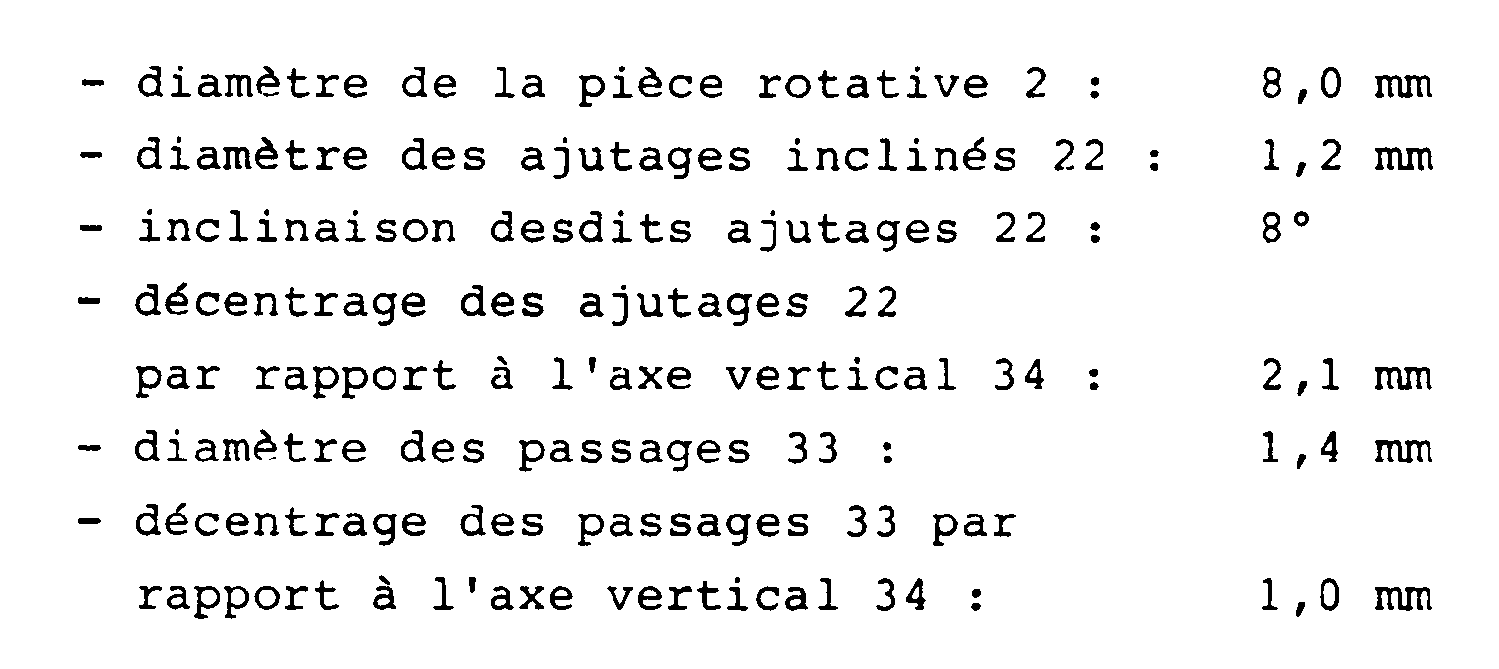
- Il est à noter que la buse selon l'invention a été particulièrement étudiée pour être réalisée dans des dimensions telles que le diamètre maximum de l'ensemble reste inférieur à 12,7 mm.
- Dans la variante de la figure 3 on a représenté une buse de giclage comportant un ajutage unique 23 faisant un angle de 30° vers l'arrière par rapport au plan transversal à l'axe de la buse. Il est à noter que dans cette variante, les ajutages 15 dirigés vers l'arrière sont supprimés. Le fluide éjecté par l'ajutage 23 sert à la fois au giclage du tuyau ainsi qu'à l'avance de l'ensemble. Pour une pièce rotative 2 de 8 mm de diamètre, on choisira de réaliser l'ajutage unique 23 à un diamètre de 1,5 à 2 mm (de préférence de 1,8 mm) et de le décentrer de 1 à 2 mm. On peut également prévoir d'augmenter l'angle de 30° à 45° environ.
- Dans cette figure 3 on a également représenté une raclette 24 destinée à agir sur la paroi intérieure du tuyau à nettoyer. La raclette 24 peut être constituée par une lame métallique, insérée dans une fente longitudinale 25 représentée à la figure 2. On pourrait aussi prévoir de remplacer la raclette 24 par une ailette disposée hélicoïdalement sur la pièce rotative 2.
- Dans la représentation de la figure 4, on a également une buse ne comportant pas les ajutages 15 vers l'arrière comme dans la figure 1. La pièce rotative 2 comporte ici deux passages : un ajutage 26 dirigé vers l'avant et faisant un angle d'environ 15° par rapport au plan tranversal à l'axe de la buse, ainsi qu'un ajutage 27 dirigé vers l'arrière et faisant un angle de l'ordre de 45° à 60° par rapport à ce même plan.
- Il est à noter qu'à la figure 4, une gorge annulaire 35 pratiquée dans le manchon cylindrique 3 remplace l'évidement annulaire 21 de la pièce rotative 2. Que l'évidement annulaire soit pratiqué à l'extérieur du manchon cylindrique 3 ou à l'intérieur de la pièce rotative 2, ses dimensions seront telles qu'il coopère d'une part avec les passages 33 et d'autre part avec les ajutages 22, 23 ou 27. Notons encore que les évidements représentés aux figures 1 à 4 présentent en coupe une forme rectangulaire, mais il est évident que toute autre forme, arrondie ou trapézoïdale par exemple, est possible, comme on le verra par la suite.
- Dans la forme d'exécution présentée aux figures 5 et 6, l'arbre creux 3 solidaire du bouchon 4 est destiné à être vissé à l'intérieur de la partie terminale du corps cylindrique (non représenté). La paroi de l'arbre creux 3 comporte, comme dans les variantes précédentes, deux passages 33 symétriquement décalés de manière à ce qu'ils soient inclinés radialement par rapport au canal. Les passage 33 débouchent dans la gorge annulaire 35 pratiquée à l'extérieur du manchon 3.
- Dans cette variante, on a représenté un bouchon 4 à tête hémisphérique munie d'une ouverture centrale 43 destinée à coopérer avec un outil de serrage, par exemple une clé à 6 pans. Il va sans dire que cette forme de bouchon peut également être utilisée dans les autres variantes décrites jusqu'ici.
- On remarquera que, dans la forme d'exécution des figures 5 et 6, le diamètre extérieur de la pièce rotative 2 est supérieur à celui du bouchon 4 pour des raisons qui seront données plus loin. La pièce rotative 2 comporte au moins un dégagement longitudinal 29.
- A la figure 6 on a représenté à la fois un dégagement longitudinal unique 29A et un dégagement double 29B constituant une raclette intermédiaire 24, mais il va sans dire que l'on peut pratiquer un seul dégagement longitudinal 29A ou 29B dans une pièce rotative. En variante on peut prévoir plusieurs dégagements 29A ou 29B, répartis à la périphérie du cylindre 2.
- En revenant à la coupe de la figure 2, on remarquera que le fluide sous pression dans le canal intérieur 11 traverse les passages 33 dans le sens de la flèche A en raison du fait que les passages 33 sont décalés par rapport à l'axe 34. Comme les ajutages 22, 23 ou 27 sont également décalés, le fluide arrivant sur la paroi 28 donne à la pièce rotative un mouvement dans le sens de la flèche B. Ainsi le mouvement du fluide en sens inverse de la pièce rotative a pour effet de freiner la rotation de cette dernière.
- Dans la variante des figures 5 et 6, le dégagement longitudinal 29 permet de créer une raclette 24 destinée à agir sur les parois internes du tube à nettoyer, qui sont râclées soit par l'élément de coupe 29A soit par la lamelle 29B.
- Les différents constituants représentés au dessin peuvent être en métal, par exemple en acier, ou en toute matière suffisamment rigide. Il peut être avantageux de réaliser la pièce rotative dans une matière plus dure que le reste de l'ensemble ou de prévoir un traitement de surface, de manière à diminuer les frottements, de manières connues de l'homme de métier.
- On peut également prévoir, pour éviter le frottement de la pièce rotative sur le manchon cylindrique 3, de réaliser sur l'une des surfaces en contact des cannelures. Pour leur réalisation on peut, par exemple, passer une filière d'un diamètre légèrement supérieur sur la partie cylindrique 3, par exemple une filière M6 sur un diamètre de 5 mm.
- On remarquera au dessin que tous les angles des constituants principaux 1 à 4 sont cassés. On notera également aux figures 1 à 4 que les diamètres extérieurs du bouchon annulaire 3 ainsi que celui du collier 5 sont légèrement supérieurs au diamètre externe de la pièce rotative 2, pour éviter qu'au cours de la progression de la buse rotative dans la tubulure à traiter la pièce rotative vienne frotter sur les parois interne de cette tubulure. Bien sûr dans la variante des figures 5 et 6, la pièce rotative a un diamètre supérieur à celui des autres éléments, pour que la raclette 24 puisse entrer en contact avec les parois du tuyau à nettoyer.
- En revenant à la représentation générale de la figure 1, on remarque que l'assemblage de la buse rotative selon l'invention est particulièrement simple puisqu'il suffit de disposer la pièce rotative 2 contre l'épaulement 14 et de visser le bouchon 4 à l'extrémité du corps creux 1. Cet ensemble est alors disposé en bout du tuyau 5 d'amenée du fluide à pulvériser et est fixé au moyen du collier de serrage 6.
- Dans la forme d'exécution présentée aux figures 7 à 10, la partie terminale 12 du corps principal 1 constitue l'arbre creux 3 précédemment mentionné, dont l'extrémité avant comporte un taraudage 13 destiné à recevoir une vis non représentée au dessin. L'extrémité opposée de corps principal 1 comporte un taraudage 18 destiné à coopérer avec un raccord non représenté au dessin, mis en bout du tuyau d'amenée du fluide à pulvériser, par le serrage de l'ensemble au moyen d'un outil approprié venant en prise avec les plats 19.
- La pièce rotative 2 présente comme précédemment un évidement annulaire 21 au niveau de deux ajutages décalés 22, inclinés l'un vers l'avant et l'autre vers l'arrière par rapport au plan transversal à l'axe de la buse et représentés à la figure 7 par les flèches 22A et 22B respectivement. L'évidement annulaire 21 débouche également dans deux ajutages 27 se faisant face, dirigés vers l'arrière, faisant un angle de 45° selon la flèche 27A des figures 7 et 9. Comme visible à ces figures, chaque ajutage 27 débouche extérieurement dans un dégagement extérieur 270, destiné à la sortie du jet de réaction perpendiculairement à la surface extérieure dudit dégagement. On peut prévoir de réaliser le dégagement extérieur 270 au moyen d'une découpe annulaire.
- On remarquera encore au dessin que pour favoriser le mouvement de la pièce rotative 2 sur l'arbre creux 3, on peut prévoir de réaliser des cannelures annulaires 210 de part et d'autre de l'évidement annulaire 21.
- Toujours à la figure 7, on remarque que le bouchon annulaire 4 présente d'une part un épaulement 41 destiné à former un palier pour la pièce rotative 2 et d'autre part une face à bord arrondi 44 sur l'avant de la buse. Il comporte de plus une ouverture centrale 45 présentant une ouverture cônique 46 destinée à recevoir la tête d'une vis d'assemblage non représentée au dessin qui vient s'insérer dans le taraudage 13 du corps principal.
- Lorsque le fluide s'échappe par les passages radiaux 27, inclinés vers l'arrière selon les flèches 27A à la figure 9, la buse rotative progresse dans la canalisation à traiter. D'autre part, lorsque le fluide passe au travers des ajutages 22, qui sont comme on l'a déjà dit décalés par rapport à l'axe du canal intérieur, on obtient la rotation de la pièce 2 et l'émission de deux faisceaux de balayage distinct, l'un dirigé vers l'avant et l'autre vers l'arrière par rapport au plan perpendiculaire à la canalisation.
- Grâce à ce double anneau de balayage, on obtient une meilleure répartition du fluide pulvérisé. De plus lorsque la buse rencontre un obstacle l'empêchant de progresser dans l'axe de la canalisation à nettoyer, les jets s'échappant des ajutages 22, en raison de la dissymétrie selon les flèches 22A et 22B, soumettent la buse à un mouvement ondulatoire par rapport à la canalisation. Au cours de ce pivotement, la nappe de fluide dirigée vers l'avant peut attaquer la masse de matière formant bouchon. Il est à noter que ce mouvement est favorisé par la forme arrondie du bouchon 4 disposé à l'avant de la buse.
Claims (25)
Priority Applications (1)
| Application Number | Priority Date | Filing Date | Title |
|---|---|---|---|
| AT88810735T ATE78723T1 (de) | 1987-10-26 | 1988-10-26 | Rotierende duese. |
Applications Claiming Priority (4)
| Application Number | Priority Date | Filing Date | Title |
|---|---|---|---|
| CH4182/87 | 1987-10-26 | ||
| CH418287A CH673095A5 (en) | 1987-10-26 | 1987-10-26 | Duct cleaner rotary spray nozzle |
| CH3177/88 | 1988-08-22 | ||
| CH3117/88A CH677326A5 (en) | 1988-08-22 | 1988-08-22 | Rotary nozzle - has rotary section with outlets and inner annular recess to give controlled speed of rotation |
Publications (3)
| Publication Number | Publication Date |
|---|---|
| EP0314629A2 EP0314629A2 (fr) | 1989-05-03 |
| EP0314629A3 EP0314629A3 (en) | 1990-03-28 |
| EP0314629B1 true EP0314629B1 (fr) | 1992-07-29 |
Family
ID=25692224
Family Applications (1)
| Application Number | Title | Priority Date | Filing Date |
|---|---|---|---|
| EP19880810735 Expired - Lifetime EP0314629B1 (fr) | 1987-10-26 | 1988-10-26 | Buse rotative |
Country Status (4)
| Country | Link |
|---|---|
| EP (1) | EP0314629B1 (fr) |
| DE (1) | DE3873261T2 (fr) |
| ES (1) | ES2034369T3 (fr) |
| GR (1) | GR3006022T3 (fr) |
Cited By (2)
| Publication number | Priority date | Publication date | Assignee | Title |
|---|---|---|---|---|
| DE102013009708A1 (de) | 2013-06-10 | 2014-12-11 | Jt-Elektronik Gmbh | Spülkopf für Abwasserkanäle und Zuführung von Medien |
| DE102013009967A1 (de) | 2013-06-13 | 2014-12-18 | Jt-Elektronik Gmbh | Mehrfach-Spüldüse für Abwasserkanäle |
Families Citing this family (5)
| Publication number | Priority date | Publication date | Assignee | Title |
|---|---|---|---|---|
| US5141158A (en) * | 1991-04-24 | 1992-08-25 | Halliburton Company | Eddy current braked spinning jet nozzle |
| DE102004036188B4 (de) * | 2004-07-26 | 2006-06-08 | Frank Zeitler | Düsenkopf für Innensprühgeräte |
| US8544768B2 (en) | 2009-11-10 | 2013-10-01 | Stoneage, Inc. | Self regulating fluid bearing high pressure rotary nozzle with balanced thrust force |
| CN107755112A (zh) * | 2017-12-06 | 2018-03-06 | 南京科远自动化集团股份有限公司 | 一种全周清洗喷头 |
| US11344930B2 (en) | 2020-02-16 | 2022-05-31 | LSQ Manufacturing, Inc. | Self-centering conduit cleaning device with reduced axial length |
Family Cites Families (6)
| Publication number | Priority date | Publication date | Assignee | Title |
|---|---|---|---|---|
| US3125297A (en) * | 1964-03-17 | Rotary spray head | ||
| BE555695A (fr) * | 1956-06-05 | |||
| DE1165945B (de) * | 1960-02-01 | 1964-03-19 | Hammelmann Paul Fa | Duesenkopf mit Schlauchanschluss zur Rohrreinigung |
| FR2404474A1 (fr) * | 1977-09-30 | 1979-04-27 | Nordon & Cie Sa | Dispositif de nettoyage de conduites |
| DE3141581A1 (de) * | 1981-10-20 | 1983-05-05 | Albrecht Wolhusen Wüthrich | Rohrreinigungsgeraet fuer kanalisationsleitungen |
| DE3428133A1 (de) * | 1983-06-24 | 1986-02-13 | Werner Dr.med. 4330 Mülheim Schubert | Reinigungskopf fuer rohrreinigungsgeraet zur beseitigung von harten inkrustierungen in leitungen |
-
1988
- 1988-10-26 DE DE19883873261 patent/DE3873261T2/de not_active Expired - Fee Related
- 1988-10-26 ES ES88810735T patent/ES2034369T3/es not_active Expired - Lifetime
- 1988-10-26 EP EP19880810735 patent/EP0314629B1/fr not_active Expired - Lifetime
-
1992
- 1992-10-19 GR GR920402353T patent/GR3006022T3/el unknown
Cited By (3)
| Publication number | Priority date | Publication date | Assignee | Title |
|---|---|---|---|---|
| DE102013009708A1 (de) | 2013-06-10 | 2014-12-11 | Jt-Elektronik Gmbh | Spülkopf für Abwasserkanäle und Zuführung von Medien |
| DE102013009708B4 (de) * | 2013-06-10 | 2018-01-11 | Jt-Elektronik Gmbh | Spülkopf für Abwasserkanäle und Zuführung von Medien |
| DE102013009967A1 (de) | 2013-06-13 | 2014-12-18 | Jt-Elektronik Gmbh | Mehrfach-Spüldüse für Abwasserkanäle |
Also Published As
| Publication number | Publication date |
|---|---|
| GR3006022T3 (fr) | 1993-06-21 |
| EP0314629A2 (fr) | 1989-05-03 |
| ES2034369T3 (es) | 1993-04-01 |
| EP0314629A3 (en) | 1990-03-28 |
| DE3873261D1 (de) | 1992-09-03 |
| DE3873261T2 (de) | 1992-12-03 |
Similar Documents
| Publication | Publication Date | Title |
|---|---|---|
| EP0314629B1 (fr) | Buse rotative | |
| FR2513730A1 (fr) | Dispositif d'assemblage pour tuyau a emboitement | |
| EP0406145A1 (fr) | Garniture d'étanchéité pour joints verrouillés étanches | |
| FR2585107A1 (fr) | Accouplement pour tuyau cannele | |
| FR2465569A1 (fr) | Manche tubulaire rond pour outils domestiques | |
| FR2741122A1 (fr) | Element de fixation | |
| CH616072A5 (fr) | ||
| WO2001094798A1 (fr) | Insert d'implantation d'un raccord de tube dans un logement taraude | |
| CA2298998A1 (fr) | Dispositif de pincement ameliore, notamment du type pince a biopsie | |
| FR2583118A1 (fr) | Dispositif dissipateur d'energie a chicanes et cavites a effet tourbillonnaire | |
| EP0325069B1 (fr) | Ecrou de fixation | |
| EP0653034B1 (fr) | Joint verrouille a emboitement entre elements tubulaires | |
| EP2359047B1 (fr) | Connecteur, système et procédé de raccordement de deux organes hydrauliques | |
| CH677326A5 (en) | Rotary nozzle - has rotary section with outlets and inner annular recess to give controlled speed of rotation | |
| FR2613628A1 (fr) | Seringue a usage unique | |
| EP0072746A2 (fr) | Lance à main pour la pulvérisation d'un liquide de traitement des plantes | |
| CH673095A5 (en) | Duct cleaner rotary spray nozzle | |
| CH628128A5 (fr) | Raccord de tuyau. | |
| FR2723475A1 (fr) | Borne de connexion, en particulier borne de connexion a entree unique | |
| WO2000031846A1 (fr) | Presse-etoupe a garniture d'etancheite et dents de serrage epaisses | |
| BE497239A (fr) | ||
| JPH09174005A (ja) | 洗浄用ノズル | |
| FR2699617A1 (fr) | Insert à douille et élément fileté. | |
| FR2798068A1 (fr) | Tete de distribution nasale de produit fluide | |
| BE434601A (fr) |
Legal Events
| Date | Code | Title | Description |
|---|---|---|---|
| PUAI | Public reference made under article 153(3) epc to a published international application that has entered the european phase |
Free format text: ORIGINAL CODE: 0009012 |
|
| AK | Designated contracting states |
Kind code of ref document: A2 Designated state(s): AT BE DE ES FR GB GR IT LU NL SE |
|
| PUAL | Search report despatched |
Free format text: ORIGINAL CODE: 0009013 |
|
| AK | Designated contracting states |
Kind code of ref document: A3 Designated state(s): AT BE DE ES FR GB GR IT LU NL SE |
|
| 17P | Request for examination filed |
Effective date: 19900219 |
|
| 17Q | First examination report despatched |
Effective date: 19911007 |
|
| GRAA | (expected) grant |
Free format text: ORIGINAL CODE: 0009210 |
|
| AK | Designated contracting states |
Kind code of ref document: B1 Designated state(s): AT BE DE ES FR GB GR IT LU NL SE |
|
| REF | Corresponds to: |
Ref document number: 78723 Country of ref document: AT Date of ref document: 19920815 Kind code of ref document: T |
|
| PGFP | Annual fee paid to national office [announced via postgrant information from national office to epo] |
Ref country code: LU Payment date: 19920827 Year of fee payment: 5 |
|
| REF | Corresponds to: |
Ref document number: 3873261 Country of ref document: DE Date of ref document: 19920903 |
|
| GBT | Gb: translation of ep patent filed (gb section 77(6)(a)/1977) | ||
| PGFP | Annual fee paid to national office [announced via postgrant information from national office to epo] |
Ref country code: GB Payment date: 19920916 Year of fee payment: 5 Ref country code: DE Payment date: 19920916 Year of fee payment: 5 |
|
| PGFP | Annual fee paid to national office [announced via postgrant information from national office to epo] |
Ref country code: BE Payment date: 19920921 Year of fee payment: 5 |
|
| PGFP | Annual fee paid to national office [announced via postgrant information from national office to epo] |
Ref country code: AT Payment date: 19920922 Year of fee payment: 5 |
|
| PGFP | Annual fee paid to national office [announced via postgrant information from national office to epo] |
Ref country code: FR Payment date: 19920924 Year of fee payment: 5 |
|
| PGFP | Annual fee paid to national office [announced via postgrant information from national office to epo] |
Ref country code: SE Payment date: 19920928 Year of fee payment: 5 |
|
| PGFP | Annual fee paid to national office [announced via postgrant information from national office to epo] |
Ref country code: ES Payment date: 19921019 Year of fee payment: 5 |
|
| ITF | It: translation for a ep patent filed |
Owner name: SOCIETA' ITALIANA BREVETTI S.P.A. |
|
| PGFP | Annual fee paid to national office [announced via postgrant information from national office to epo] |
Ref country code: GR Payment date: 19921029 Year of fee payment: 5 |
|
| PGFP | Annual fee paid to national office [announced via postgrant information from national office to epo] |
Ref country code: NL Payment date: 19921031 Year of fee payment: 5 |
|
| EPTA | Lu: last paid annual fee | ||
| REG | Reference to a national code |
Ref country code: ES Ref legal event code: FG2A Ref document number: 2034369 Country of ref document: ES Kind code of ref document: T3 |
|
| REG | Reference to a national code |
Ref country code: GR Ref legal event code: FG4A Free format text: 3006022 |
|
| PLBE | No opposition filed within time limit |
Free format text: ORIGINAL CODE: 0009261 |
|
| STAA | Information on the status of an ep patent application or granted ep patent |
Free format text: STATUS: NO OPPOSITION FILED WITHIN TIME LIMIT |
|
| 26N | No opposition filed | ||
| PG25 | Lapsed in a contracting state [announced via postgrant information from national office to epo] |
Ref country code: LU Free format text: LAPSE BECAUSE OF NON-PAYMENT OF DUE FEES Effective date: 19931026 Ref country code: GB Effective date: 19931026 Ref country code: AT Effective date: 19931026 |
|
| PG25 | Lapsed in a contracting state [announced via postgrant information from national office to epo] |
Ref country code: SE Effective date: 19931027 Ref country code: ES Free format text: LAPSE BECAUSE OF THE APPLICANT RENOUNCES Effective date: 19931027 |
|
| PG25 | Lapsed in a contracting state [announced via postgrant information from national office to epo] |
Ref country code: BE Effective date: 19931031 |
|
| BERE | Be: lapsed |
Owner name: S.A. EXITFLEX Effective date: 19931031 |
|
| PG25 | Lapsed in a contracting state [announced via postgrant information from national office to epo] |
Ref country code: GR Free format text: THE PATENT HAS BEEN ANNULLED BY A DECISION OF A NATIONAL AUTHORITY Effective date: 19940430 |
|
| PG25 | Lapsed in a contracting state [announced via postgrant information from national office to epo] |
Ref country code: NL Effective date: 19940501 |
|
| NLV4 | Nl: lapsed or anulled due to non-payment of the annual fee | ||
| GBPC | Gb: european patent ceased through non-payment of renewal fee |
Effective date: 19931026 |
|
| PG25 | Lapsed in a contracting state [announced via postgrant information from national office to epo] |
Ref country code: FR Effective date: 19940630 |
|
| PG25 | Lapsed in a contracting state [announced via postgrant information from national office to epo] |
Ref country code: DE Effective date: 19940701 |
|
| REG | Reference to a national code |
Ref country code: FR Ref legal event code: ST |
|
| REG | Reference to a national code |
Ref country code: GR Ref legal event code: MM2A Free format text: 3006022 |
|
| EUG | Se: european patent has lapsed |
Ref document number: 88810735.6 Effective date: 19940510 |
|
| REG | Reference to a national code |
Ref country code: ES Ref legal event code: FD2A Effective date: 19991007 |
|
| PG25 | Lapsed in a contracting state [announced via postgrant information from national office to epo] |
Ref country code: IT Free format text: LAPSE BECAUSE OF NON-PAYMENT OF DUE FEES;WARNING: LAPSES OF ITALIAN PATENTS WITH EFFECTIVE DATE BEFORE 2007 MAY HAVE OCCURRED AT ANY TIME BEFORE 2007. THE CORRECT EFFECTIVE DATE MAY BE DIFFERENT FROM THE ONE RECORDED. Effective date: 20051026 |