EP0314591A1 - Tree stump eradicator - Google Patents
Tree stump eradicator Download PDFInfo
- Publication number
- EP0314591A1 EP0314591A1 EP88440090A EP88440090A EP0314591A1 EP 0314591 A1 EP0314591 A1 EP 0314591A1 EP 88440090 A EP88440090 A EP 88440090A EP 88440090 A EP88440090 A EP 88440090A EP 0314591 A1 EP0314591 A1 EP 0314591A1
- Authority
- EP
- European Patent Office
- Prior art keywords
- removal tool
- cutting
- stump removal
- stump
- vertical
- Prior art date
- Legal status (The legal status is an assumption and is not a legal conclusion. Google has not performed a legal analysis and makes no representation as to the accuracy of the status listed.)
- Granted
Links
Images
Classifications
-
- A—HUMAN NECESSITIES
- A01—AGRICULTURE; FORESTRY; ANIMAL HUSBANDRY; HUNTING; TRAPPING; FISHING
- A01G—HORTICULTURE; CULTIVATION OF VEGETABLES, FLOWERS, RICE, FRUIT, VINES, HOPS OR SEAWEED; FORESTRY; WATERING
- A01G23/00—Forestry
- A01G23/02—Transplanting, uprooting, felling or delimbing trees
- A01G23/06—Uprooting or pulling up trees; Extracting or eliminating stumps
Definitions
- the invention relates to a stump removal tool for earth-moving machinery comprising an articulated arm to which is made integral, by appropriate connection means, said tool.
- This invention will find its utility, more particularly, in the industry specialized in the manufacture of earth-moving machines with hydraulic power transmission and their accessories.
- a stump removal tool has been designed which, by means of connection means, can be made integral with an articulated arm usually fitted to earth-moving machinery with hydraulic power transmission.
- these stump removal tools are composed, on the one hand, of an elongated spur whose front edge is bevelled so as to form a sharp edge intended to split the stump in a vertical plane.
- This stump removal tool further comprises a cutting blade arranged in a substantially horizontal plane and attached to one of the lateral sides of the aforementioned spur.
- the spur is intended, after engagement in the latter, to guide the movement of the stump removal tool and is, for this purpose, projecting relative to the blade of chopped off.
- the cutting blade can present, on its front and rear edges, a series of teeth cut in steps each having a perpendicular cutting edge in the vertical plane of the spur. This particular configuration tends to make it easier for the wood to burst under the effect of the pressure exerted by the stump removal tool.
- this cutting blade when entering the stump, this cutting blade meets increasing resistance and, due to its lateral offset, forms a large lever arm tending to twist the tool and, ultimately, the articulated arm of the earthmoving machine.
- the fact of first engaging the spur in the stump gives rise to frictional forces which are added to those exerted on the cutting blade when it comes into action.
- the object of the present invention is to remedy all of the aforementioned drawbacks by proposing a stump removal tool which makes it possible to obtain better distribution of the forces applied to the articulated arm of an earth-moving machine.
- Another object of the present invention to provide a stump removal tool whose efficiency and performance are improved without increasing, however, maintenance difficulties.
- the invention solves the problem of creating a stump removal tool for earth-moving machinery comprising an articulated arm to which is made integral, by appropriate connection means, said tool, ci comprising horizontal cutting means constituted by a metal plate arranged horizontally and attached to the lower end of a post, of small thickness, made integral, at its upper part, connection means and constituting a vertical cutting blade, said horizontal cutting means extending on either side and, substantially, in front of the vertical cutting blade.
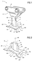
- Figure 1 shows a schematic perspective view of the stump removal tool according to the invention.
- FIG. 2 shows a detailed view of Figure 1 and illustrating the horizontal cutting means located on either side of the vertical cutting blade.
- stump removal tool 1 is intended more particularly for use by earth-moving machinery with hydraulic power transmission.
- this stump removal tool 1 comprises, in its upper part 2, connection means 3 allowing its cooperation with the free end of an articulated arm of such an earthmoving machine.
- connection means 3 are determined by the skilled person, depending on the machine to which the grubbing tool 1 must be adapted, and, therefore, are independent of the present invention.
- the latter relates to the elements of the lower part 4 of the stump removal tool 1 and whose particular characteristics considerably facilitate the destruction and removal of the stumps.
- this stump removal tool 1 is provided with horizontal cutting means 5,6 surmounted by a vertical cutting blade 7, said horizontal cutting means 5, 6 being located on either side and in front of the latter.
- the vertical cutting blade 7 is formed of an upright 8 disposed in the vertical median plane 9 of the grubbing tool 1 and made integral, at its upper part 10, with connection means 3.
- This upright 8, of small thickness comprises, on its front edge 11, a wedge-shaped element 12 whose cutting edge 13, arranged vertically, makes it possible to split the wood to allow the passage of the stump removal tool 1 and, finally , destroy the strain.
- the wedge-shaped element 12 can, as the case may be, form part of the mass constituting the upright 8 or attached, by welding or otherwise, to the front edge 11 of the latter.
- the wedge-shaped element 12 can advantageously be made of a particularly resistant material and having the properties required for cutting the stumps.
- a metal dish 15 disposed horizontally extending symmetrically on either side of the vertical median plane 9 of the grubbing tool 1 and defining the means of horizontal section 5.6.
- the metal dish 15 comprises, in its front edge 16, a cutout 17 making it possible to define two cutting elements 18, 19 located on either side of the vertical median plane 9 of the grubbing tool 1.
- the cutting elements 18, 19 have a bevel cut on their upper face 20 giving them a cutting edge 21 perpendicular to the vertical median plane 9.
- the metal plate 15 is bevelled on its upper face 24 and at its front edge 23, delimited by the cutting elements 18, 19, this in order to obtain a cutting edge 25 reducing the coefficient of resistance to the penetration of the grubbing tool 1 into any strain.
- this stump removal tool 1 has, in its lower part 4, a structure that is substantially symmetrical with respect to a transverse median plane 26.
- this stump removal tool 1 has, in its rear part 27, the same elements and characteristics as those described above. above and located in the front part 28.
- the advantage of such an arrangement consists, essentially, in that the stump removal tool 1 can work either under pressure or under traction depending on the action exerted by the articulated arm of the earth-moving machine.
- cuts 31 are made in the lateral edges 29, 30 of said metal plate 15 making it possible to reduce its section and, consequently, the forces applied to it at the time of cutting.
- the metal dish 15 is given a substantially concave shape in slightly raising its lateral edges 32.
- the horizontal cutting means 5, 6 thus take the appearance of a gouge which is known to be of interest in fields such as cabinetmaking, carpentry and others. Indeed, this particular shape promotes the engagement of the stump tool 1 in the thickness of the wood and thereby increases its efficiency and yield.
- the articulated arm controlled by the earth-moving machine with hydraulic power transmission, transmits a circular movement to the grubbing tool 1.
- this efficiency of the horizontal cutting means 5, 6 can also be improved by giving the metallic dish 15 a semi-cylindrical shape, concentric with an axis perpendicular to the vertical median plane 9.
- this shape is obtained by raising, respectively, the front and rear part of this metallic dish 15. This characteristic improves the performance of the stump removal tool 1 by promoting its plunging into the stump, due to the rocking movement communicated via the above-mentioned articulated arm.
- the main advantages obtained thanks to this invention consist, essentially, in that one gains in efficiency, therefore in speed of work to be executed while avoiding using the earthmoving machine of excessive power. Furthermore, due to a better distribution of the forces exerted on the stump removal tool, the stresses applied to the articulated arm are less significant.
Abstract
Description
L'invention concerne un outil d'essouchement pour engins de terrassement comprenant un bras articulé auquel est rendu solidaire, par des moyens de raccordement appropriés, ledit outil.The invention relates to a stump removal tool for earth-moving machinery comprising an articulated arm to which is made integral, by appropriate connection means, said tool.
Cette invention trouvera son utilité, plus particulièrement, dans l'industrie spécialisée dans la fabrication d'engins de terrassement à transmission de force hydraulique et leurs accessoires.This invention will find its utility, more particularly, in the industry specialized in the manufacture of earth-moving machines with hydraulic power transmission and their accessories.
Fréquemment, avant de procéder à des travaux de terrassement, il s'avère nécessaire d'éliminer les différentes souches provenant d'un abattage d'arbres qui a été effectué sur les lieux.Frequently, before carrying out earthworks, it turns out to be necessary to eliminate the various stumps coming from a felling of trees which was carried out on the spot.
La solution la plus simple en ce qu'elle ne nécessite aucun outillage spécialisé consiste à évacuer la terre tout autour de ces souches, puis à sectionner leurs racines avant de les extraire du sol. Ce procédé est d'exécution longue et entraîne des dégradations considérables de l'état du terrain en le rendant particulièrement accidenté. En conséquence, les engins de terrassement vont rencontrer, ultérieurement, d'importantes difficultés pour se mouvoir en raison de la quantité non négligeable de terre retournée qui, en période de pluie, donne naissance à de nombreux bourbiers. Cette solution, malgré sa simplicité, perd, de ce fait, tout son attrait.The simplest solution in that it does not require any specialized tools is to evacuate the earth all around these stumps, then to cut their roots before extracting them from the ground. This process is long-lasting and causes considerable deterioration of the condition of the ground, making it particularly uneven. Consequently, earth-moving machinery will later encounter major difficulties in moving due to the not insignificant quantity of earth turned over which, during rainy periods, gives rise to numerous quagmires. This solution, despite its simplicity, therefore loses all its appeal.
Pour remédier aux inconvénients précités, il a été conçu un outil d'essouchement qui, par l'intermédiaire de moyens de raccordement, peut être rendu solidaire d'un bras articulé équipant, habituellement, les engins de terrassement à transmission de force hydraulique.To remedy the aforementioned drawbacks, a stump removal tool has been designed which, by means of connection means, can be made integral with an articulated arm usually fitted to earth-moving machinery with hydraulic power transmission.
Ainsi, ces outils d'essouchement sont composés, d'une part, d'un éperon de forme allongée dont le chant avant est biseauté de manière à former un bord tranchant destiné à fendre la souche suivant un plan vertical. Cet outil d'essouchement comporte, en outre, une lame de coupe disposée dans un plan sensiblement horizontal et rapporté sur l'un des côtés latéraux de l'éperon précité. En dehors de la fonction qui consiste à fendre la souche, l'éperon est destiné, après engagement dans cette dernière, à guider le déplacement de l'outil d'essouchement et se présente, à cet effet, saillant par rapport à la lame de coupe.Thus, these stump removal tools are composed, on the one hand, of an elongated spur whose front edge is bevelled so as to form a sharp edge intended to split the stump in a vertical plane. This stump removal tool further comprises a cutting blade arranged in a substantially horizontal plane and attached to one of the lateral sides of the aforementioned spur. Apart from the function which consists in splitting the stump, the spur is intended, after engagement in the latter, to guide the movement of the stump removal tool and is, for this purpose, projecting relative to the blade of chopped off.
De manière à faciliter son engagement dans l'épaisseur du bois que constitue la souche et réduire les forces de frottement, la lame de coupe peut présenter, sur son chant avant et arrière, une série de dents taillées en escalier ayant chacune un bord tranchant perpendiculaire au plan vertical de l'éperon. Cette configuration particulière a tendance à rendre plus aisé l'éclatement du bois sous l'effet de la pression exercée par l'outil d'essouchement .In order to facilitate its engagement in the thickness of the wood that constitutes the stump and reduce the frictional forces, the cutting blade can present, on its front and rear edges, a series of teeth cut in steps each having a perpendicular cutting edge in the vertical plane of the spur. This particular configuration tends to make it easier for the wood to burst under the effect of the pressure exerted by the stump removal tool.
Cependant, les nombreux inconvénients que présente un tel outil d'essouchement proviennent essentiellement de sa structure et de la combinaison spécifique de l'éperon et d'une lame de coupe rapportée sur l'un des côtés latéraux de ce dernier.However, the numerous drawbacks that such a stump removal tool presents essentially come from its structure and the specific combination of the spur and a cutting blade attached to one of the lateral sides of the latter.
Ainsi, au moment de pénétrer dans la souche, cette lame de coupe rencontre une résistance croissante et, en raison de son déport latéral, forme un bras de levier important ayant tendance à vriller l' outil et, finalement, le bras articulé de l'engin de terrassement. Du plus, le fait d'engager, en premier, l'éperon dans la souche donne naissance à des forces de frottement venant à s'additionner à celles exercées sur la lame de coupe au moment d'entrer en action. Cependant, à cet instant même, il est primordial que ladite lame de coupe pénètre de manière la plus efficace possible dans l'épaisseur du bois pour provoquer l'éclatement de la souche.Thus, when entering the stump, this cutting blade meets increasing resistance and, due to its lateral offset, forms a large lever arm tending to twist the tool and, ultimately, the articulated arm of the earthmoving machine. In addition, the fact of first engaging the spur in the stump gives rise to frictional forces which are added to those exerted on the cutting blade when it comes into action. However, at this very moment, it is essential that said cutting blade penetrate as effectively as possible into the thickness of the wood to cause the stump to burst.
En conséquence, l'utilisation de cet outil d'essouchement connu nécessite des engins de terrassement à transmission de force hydraulique extrêmement puissants pour obtenir des résultats concluants et autoriser la destruction de sources de diamètre important.Consequently, the use of this known stump removal tool requires extremely powerful earthmoving machines with hydraulic power transmission to obtain conclusive results and authorize the destruction of sources of large diameter.
Un autre inconvénient que présente un tel outil d'essouchement réside dans les dentures en forme d'escaliers usinées sur les bords tranchants de la lame de coupe.Another disadvantage of such a stump removal tool is the teeth in the form of stairs machined on the sharp edges of the cutting blade.
En effet, le taillage de ces dentures est particulièrement difficile à exécuter en raison de la dureté relativement élevée des matériaux utilisés pour la réalisation desdits outils d'essouchement. De tels matériaux sont, cependant, indispensables pour permettre à ces derniers d'être performants et de résister aux différentes sollicitations qui leur sont appliquées.Indeed, the cutting of these teeth is particularly difficult to perform due to the relatively high hardness of the materials used for the production of said grubbing tools. Such materials are, however, essential to allow the latter to be efficient and to resist the various stresses which are applied to them.
De plus, il ne faut pas négliger que le tranchant de la lame de coupe et de l'éperon doit être repris fréquemment, sans quoi, l'outil perd de son efficacité. Or, les dentures rendent cette opération particulièrement difficile et fastidieuse.In addition, it should not be overlooked that the cutting edge of the cutting blade and the spur must be taken up frequently, otherwise the tool will lose its effectiveness. However, the teeth make this operation particularly difficult and tedious.
La présente invention a pour but de remédier à l'ensemble des inconvénients précités en proposant un outil d'essouchement qui permette d'obtenir une meilleure répartition des efforts appliqués sur le bras articulé d'un engin de terrassement.The object of the present invention is to remedy all of the aforementioned drawbacks by proposing a stump removal tool which makes it possible to obtain better distribution of the forces applied to the articulated arm of an earth-moving machine.
Un autre but de la présente invention consiste à proposer un outil d'essouchement dont l'efficacité et le rendement sont améliorés sans accroître, pour autant, les difficultés d'entretien.Another object of the present invention to provide a stump removal tool whose efficiency and performance are improved without increasing, however, maintenance difficulties.
L'invention, telle qu'elle est caractérisée dans les revendications, résout le problème consistant à créer un outil d'essouchement pour engins de terrassement comprenant un bras articulé auquel est rendu solidaire, par des moyens de raccordement appropriés, ledit outil, celui-ci comportant des moyens de coupe horizontale constitués par un plat métallique disposé horizontalement et rapporté à l'extrémité inférieure d'un montant, de faible épaisseur, rendu solidaire, à sa partie supérieure, des moyens de raccordement et constituant une lame de coupe verticale, lesdits moyens de coupe horizontale s'étendant de part de d'autre et, sensiblement, en avant de la lame de coupe verticale.The invention, as characterized in the claims, solves the problem of creating a stump removal tool for earth-moving machinery comprising an articulated arm to which is made integral, by appropriate connection means, said tool, ci comprising horizontal cutting means constituted by a metal plate arranged horizontally and attached to the lower end of a post, of small thickness, made integral, at its upper part, connection means and constituting a vertical cutting blade, said horizontal cutting means extending on either side and, substantially, in front of the vertical cutting blade.
Les avantages obtenus grâce à cette invention consistent essentiellement en ce que la disposition particulière des moyens de coupe horizontale par rapport à la lame de coupe verticale favorise, simultanément, l'engagement de l'outil d'essouchement dans l'épaisseur du bois d'une souche et l'éclatement de cette dernière.The advantages obtained thanks to this invention consist essentially in that the particular arrangement of the horizontal cutting means with respect to the vertical cutting blade simultaneously promotes the engagement of the stump tool in the thickness of the wood. a strain and the bursting of the latter.
L'invention est exposée ci-après plus en détail à l'aide de dessins représentant seulement un mode d'exécution.The invention is set out below in more detail with the aid of drawings representing only one embodiment.
La figure 1 représente une vue schématisée et en perspective de l'outil d'essouchement conforme à l'invention.Figure 1 shows a schematic perspective view of the stump removal tool according to the invention.
La figure 2 représente une vue de détail de la figure 1 et illustrant les moyens de coupe horizontale situés de part et d'autre de la lame de coup verticale.2 shows a detailed view of Figure 1 and illustrating the horizontal cutting means located on either side of the vertical cutting blade.
On se réfère aux différentes figures.We refer to the different figures.
L'outil d'essouchement 1, conforme à l'invention et dont la description va suivre, est destiné plus particulièrement à être utilisé par des engins de terrassement à transmission de force hydraulique. A cet effet, cet outil d'essouchement 1 comporte, dans sa partie supérieure 2, des moyens de raccordement 3 autorisant sa coopération avec l'extrémité libre d'un bras articulé d'un tel engin de terrassement.The
La structure et la configuration de ces moyens de raccordement 3 sont déterminées par l'Homme du Métier considéré, en fonction de l'engin auquel doit être adapté l'outil d'essouchement 1, et, sont, en conséquence, indépendantes de la présente invention.The structure and configuration of these connection means 3 are determined by the skilled person, depending on the machine to which the
Plus précisément, cette dernière concerne les éléments de la partie inférieure 4 de l'outil d'essouchement 1 et dont les caractéristiques particulières facilitent considérablement la destruction et l'enlèvement des souches.More specifically, the latter relates to the elements of the lower part 4 of the
Ainsi, cet outil d'essouchement 1 est muni de moyens de coupe horizontale 5,6 surmontés d'une lame de coupe verticale 7, lesdits moyens de coupe horizontale 5, 6 étant situés de part et d'autre et à l'avant de cette dernière.Thus, this
Plus précisément, la lame de coupe verticale 7 est formée d'un montant 8 disposé dans le plan médian vertical 9 de l'outil d'essouchement 1 et rendue solidaire, à sa partie supérieure 10, des moyens de raccordement 3. Ce montant 8, de faible épaisseur, comporte, sur son chant avant 11, un élément en forme de coin 12 dont le bord tranchant 13, disposé verticalement, permet de fendre le bois pour autoriser le passage de l'outil d'essouchement 1 et, finalement, détruire la souche.More specifically, the
Il est à remarquer que l'élément en forme de coin 12 peut, selon le cas, faire partie de la masse constituant le montant 8 ou rapporté, par soudage ou autre, sur le chant avant 11 de ce dernier. Dans ce dernier cas, l'élément en forme de coin 12 peut être réalisé, avantageusement, en un matériau particulièrement résistant et présentant les propriétés requises pour la coupe des souches.It should be noted that the wedge-
A l'extrémité inférieure 14 dudit montant 8 ou lame de coupe 7 est rapporté un plat métallique 15 disposé horizontalement s'étendant symétriquement de part et d'autre du plan médian vertical 9 de l'outil d'essouchement 1 et définissant les moyens de coupe horizontale 5,6.At the
Selon un mode de réalisation préférentiel, le plat métallique 15 comporte, dans son chant avant 16, une découpe 17 permettant de définir deux éléments tranchants 18, 19 situés de part et d'autre du plan médian vertical 9 de l'outil d'essouchement 1.According to a preferred embodiment, the
Avantageusement les éléments tranchants 18, 19 présentent sur leur face supérieure 20 une coupe en biseau leur conférant un bord tranchant 21 perpendiculaire au plan médian vertical 9.Advantageously, the
Tel que visible dans la figure 2, les bords latéraux 22 de la découpe 17 vont en s'évasant de l'intérieur vers l'extérieur. Cette configuration assure aux éléments tranchants 18, 19 une taille en oblique 33 favorisant leur engagement progressif dans l'épaisseur du bois et l'éclatement de ce dernier.As visible in Figure 2, the
Il est à remarquer, en outre, que le plat métallique 15 est biseauté sur sa face supérieure 24 et au niveau de son bord avant 23, délimité par les éléments tranchants 18, 19, ceci dans le but d'obtenir un bord tranchant 25 réduisant le coefficient de résistance à la pénétration de l'outil d'essouchement 1 dans une souche quelconque.It should be noted, moreover, that the
Avantageusement, cet outil d'essouchement 1 présente, dans sa partie inférieure 4, une structure sensiblement symétrique par rapport à un plan médian transversal 26. De ce fait, on retrouve dans sa partie arrière 27 les mêmes éléments et caractéristiques que ceux décrits ci-dessus et situés dans la partie avant 28.Advantageously, this
L'avantage d'une telle disposition consiste, essentiellement, en ce que l'outil d'essouchement 1 peut travailler soit en pression, soit en traction selon l'action exercée par le bras articulé de l'engin de terrassement.The advantage of such an arrangement consists, essentially, in that the
Cependant, cette spécificité confère au plat métallique 15 une surface relativement importante ayant tendance à augmenter les forces de frottement exercées sur l'outil d'essouchement 1 lors d'une destruction de souche.However, this specificity gives the metal dish 15 a relatively large surface which tends to increase the frictional forces exerted on the
Pour remédier à cet inconvénient, on réalise dans les chants latéraux 29, 30 dudit plat métallique 15 des découpes 31 permettant de réduire sa section et, en conséquence, les efforts qui lui sont appliqués au moment de la coupe.To overcome this drawback,
Selon un autre mode de réalisation, on confère au plat métallique 15 une forme sensiblement concave en rehaussant légèrement ses bords latéraux 32. Les moyens de coupe horizontale 5, 6 empruntent, ainsi, l'aspect d'une gouge dont on connaît l'intérêt dans les domaines tels que l'ébénisterie, la menuiserie et autres. En effet, cette forme particulière favorise l'engagement de l'outil d'essouchement 1 dans l'épaisseur du bois et accroît, de ce fait, son efficacité et son rendement.According to another embodiment, the
Cependant, on constate, qu'en règle générale, le bras articulé, commandé par l'engin de terrassement à transmission de force hydraulique, transmet un mouvement circulaire à l'outil d'essouchement 1. Ainsi, cette efficacité des moyens de coupe horizontale 5, 6 peut également être amêliorée en conférant au plat métallique 15 une forme hémicylindrique, concentrique à un axe perpendiculaire au plan médian vertical 9. Ainsi, cette forme est obtenue en relevant, respectivement, la partie avant et arrière de ce plat métallique 15. Cette caractéristique améliore le rendement de l'outil d'essouchement 1 en favorisant sa plongée dans la souche et ce, en raison du mouvement basculant communiqué par l'intermédiaire du bras articulé précité.However, it can be seen that, as a general rule, the articulated arm, controlled by the earth-moving machine with hydraulic power transmission, transmits a circular movement to the
Les principaux avantages obtenus grâce à cette invention consistent, essentiellement, en ce que l'on gagne en efficacité, donc en rapidité des travaux à exécuter tout en évitant d'utiliser l'engin de terrassement d'une puissance excessive. Par ailleurs, en raison d'une meilleure répartition des efforts exercés sur l'outil d'essouchement, les contraintes appliquées au bras articulé sont moins importantes.The main advantages obtained thanks to this invention consist, essentially, in that one gains in efficiency, therefore in speed of work to be executed while avoiding using the earthmoving machine of excessive power. Furthermore, due to a better distribution of the forces exerted on the stump removal tool, the stresses applied to the articulated arm are less significant.
Claims (7)
Applications Claiming Priority (2)
| Application Number | Priority Date | Filing Date | Title |
|---|---|---|---|
| FR8715133 | 1987-10-28 | ||
| FR8715133A FR2622391B1 (en) | 1987-10-28 | 1987-10-28 | STRAINING TOOL |
Publications (2)
| Publication Number | Publication Date |
|---|---|
| EP0314591A1 true EP0314591A1 (en) | 1989-05-03 |
| EP0314591B1 EP0314591B1 (en) | 1992-01-22 |
Family
ID=9356384
Family Applications (1)
| Application Number | Title | Priority Date | Filing Date |
|---|---|---|---|
| EP19880440090 Expired - Lifetime EP0314591B1 (en) | 1987-10-28 | 1988-10-25 | Tree stump eradicator |
Country Status (3)
| Country | Link |
|---|---|
| EP (1) | EP0314591B1 (en) |
| DE (1) | DE3868004D1 (en) |
| FR (1) | FR2622391B1 (en) |
Cited By (2)
| Publication number | Priority date | Publication date | Assignee | Title |
|---|---|---|---|---|
| EP1921212A2 (en) * | 2006-11-13 | 2008-05-14 | van Vulpen, Jan | Method and device for disposing of underground obstacles, and a knife for use with such a device |
| WO2009149696A2 (en) | 2008-06-10 | 2009-12-17 | Hartmut Neidlein | Clearing blade |
Citations (3)
| Publication number | Priority date | Publication date | Assignee | Title |
|---|---|---|---|---|
| US4094348A (en) * | 1976-11-19 | 1978-06-13 | Wolf Robert H | Tree and stump splitter |
| EP0161169A1 (en) * | 1984-04-13 | 1985-11-13 | André Becker | Tree stump eradicator |
| FR2615354A1 (en) * | 1987-05-18 | 1988-11-25 | Gal Sarl | Tool for extracting the stumps of felled trees |
-
1987
- 1987-10-28 FR FR8715133A patent/FR2622391B1/en not_active Expired - Lifetime
-
1988
- 1988-10-25 EP EP19880440090 patent/EP0314591B1/en not_active Expired - Lifetime
- 1988-10-25 DE DE8888440090T patent/DE3868004D1/en not_active Expired - Lifetime
Patent Citations (3)
| Publication number | Priority date | Publication date | Assignee | Title |
|---|---|---|---|---|
| US4094348A (en) * | 1976-11-19 | 1978-06-13 | Wolf Robert H | Tree and stump splitter |
| EP0161169A1 (en) * | 1984-04-13 | 1985-11-13 | André Becker | Tree stump eradicator |
| FR2615354A1 (en) * | 1987-05-18 | 1988-11-25 | Gal Sarl | Tool for extracting the stumps of felled trees |
Cited By (6)
| Publication number | Priority date | Publication date | Assignee | Title |
|---|---|---|---|---|
| EP1921212A2 (en) * | 2006-11-13 | 2008-05-14 | van Vulpen, Jan | Method and device for disposing of underground obstacles, and a knife for use with such a device |
| EP1921212A3 (en) * | 2006-11-13 | 2009-05-13 | van Vulpen, Jan | Method and device for disposing of underground obstacles, and a knife for use with such a device |
| WO2009149696A2 (en) | 2008-06-10 | 2009-12-17 | Hartmut Neidlein | Clearing blade |
| WO2009149696A3 (en) * | 2008-06-10 | 2010-02-18 | Hartmut Neidlein | Clearing blade |
| AT10876U3 (en) * | 2008-06-10 | 2010-06-15 | Neidlein Hartmut | GRUBBING KNIFE |
| EP2252139B2 (en) † | 2008-06-10 | 2019-12-25 | Hartmut Neidlein | Clearing blade |
Also Published As
| Publication number | Publication date |
|---|---|
| DE3868004D1 (en) | 1992-03-05 |
| FR2622391A1 (en) | 1989-05-05 |
| EP0314591B1 (en) | 1992-01-22 |
| FR2622391B1 (en) | 1991-06-21 |
Similar Documents
| Publication | Publication Date | Title |
|---|---|---|
| EP0161169B1 (en) | Tree stump eradicator | |
| FR2530915A1 (en) | WORKING MACHINE WITH A TOOTH ROLL | |
| EP1900269B1 (en) | Wearing part and its fixing, plough body and plough comprising such a wearing part | |
| EP0314591B1 (en) | Tree stump eradicator | |
| EP1479287A1 (en) | Device for sterilization of soil | |
| FR2587579A1 (en) | AGRICULTURAL FLOOR MACHINE WITH ROTOR DRAWN AROUND AN OBLIQUE AXIS | |
| FR2607424A1 (en) | CHAIN CHAINSAW | |
| FR2547696A1 (en) | Disc for agricultural work and combined land packer and roller tiller equipped with a plurality of such discs | |
| FR2545678A1 (en) | GROWER EQUIPPED WITH EARTH WHEELS INCREASING ITS STABILITY | |
| FR2485868A1 (en) | SOIL WORKING MACHINE SUITABLE IN PARTICULAR FOR THE PREPARATION OF SEED BEDS | |
| FR2530916A1 (en) | WORKING MACHINE WITH A TOOTH ROLL | |
| EP1900268B1 (en) | Wearing part and its fixing with a wedge, plough body and plough comprising such a wearing part | |
| EP0279761A1 (en) | Tine for cultivating the soil, and implement equipped with such a tine | |
| FR2669658A1 (en) | Rake for clearing undergrowth, in particular for public works machines | |
| FR2737078A1 (en) | Portable hydraulic pruner, e.g. for pruning in forests, fruit pruning, etc. - consists of hydraulic unit, supplying pressurised fluid to cutting head with double acting jack to drive lower cutter against fixed counter blade | |
| EP1546471B1 (en) | Excavating tool for hydraulic shovel | |
| FR2605491A1 (en) | Forestry tool for brush clearing (tree-dozing) and for felling | |
| FR2553255A1 (en) | Self-propelled device intended for uprooting nursery trees with root balls | |
| BE478135A (en) | ||
| FR2615354A1 (en) | Tool for extracting the stumps of felled trees | |
| FR2823465A1 (en) | Wood cutting implement esp for tree stumps has clamps with toothed fixed jaws and blades operated by power cylinders | |
| FR2458980A1 (en) | IMPROVEMENTS TO ARATORY INSTRUMENTS FOR WORKING EARTH | |
| FR2672912A1 (en) | Chain saw (cutter) | |
| FR2854763A1 (en) | Soil tilling blade has chisel tip with raised rear end to break up lifted strip of soil | |
| FR3069408A1 (en) | SOIL WORKING MACHINE COMPRISING AT LEAST ONE ROLL WHICH HAS SEGMENTS HAVING AN IMPROVED GEOMETRY |
Legal Events
| Date | Code | Title | Description |
|---|---|---|---|
| PUAI | Public reference made under article 153(3) epc to a published international application that has entered the european phase |
Free format text: ORIGINAL CODE: 0009012 |
|
| AK | Designated contracting states |
Kind code of ref document: A1 Designated state(s): BE DE GB SE |
|
| 17P | Request for examination filed |
Effective date: 19890911 |
|
| 17Q | First examination report despatched |
Effective date: 19901005 |
|
| GRAA | (expected) grant |
Free format text: ORIGINAL CODE: 0009210 |
|
| AK | Designated contracting states |
Kind code of ref document: B1 Designated state(s): BE DE GB SE |
|
| REF | Corresponds to: |
Ref document number: 3868004 Country of ref document: DE Date of ref document: 19920305 |
|
| GBT | Gb: translation of ep patent filed (gb section 77(6)(a)/1977) | ||
| PLBE | No opposition filed within time limit |
Free format text: ORIGINAL CODE: 0009261 |
|
| STAA | Information on the status of an ep patent application or granted ep patent |
Free format text: STATUS: NO OPPOSITION FILED WITHIN TIME LIMIT |
|
| 26N | No opposition filed | ||
| PGFP | Annual fee paid to national office [announced via postgrant information from national office to epo] |
Ref country code: GB Payment date: 19931015 Year of fee payment: 6 |
|
| PGFP | Annual fee paid to national office [announced via postgrant information from national office to epo] |
Ref country code: BE Payment date: 19931130 Year of fee payment: 6 |
|
| PG25 | Lapsed in a contracting state [announced via postgrant information from national office to epo] |
Ref country code: GB Effective date: 19941025 |
|
| PG25 | Lapsed in a contracting state [announced via postgrant information from national office to epo] |
Ref country code: BE Effective date: 19941031 |
|
| EAL | Se: european patent in force in sweden |
Ref document number: 88440090.4 |
|
| BERE | Be: lapsed |
Owner name: PLAISANCE JEAN-MARIE Effective date: 19941031 |
|
| GBPC | Gb: european patent ceased through non-payment of renewal fee |
Effective date: 19941025 |
|
| PGFP | Annual fee paid to national office [announced via postgrant information from national office to epo] |
Ref country code: SE Payment date: 19951017 Year of fee payment: 8 |
|
| PGFP | Annual fee paid to national office [announced via postgrant information from national office to epo] |
Ref country code: DE Payment date: 19951026 Year of fee payment: 8 |
|
| PG25 | Lapsed in a contracting state [announced via postgrant information from national office to epo] |
Ref country code: SE Effective date: 19961026 |
|
| PG25 | Lapsed in a contracting state [announced via postgrant information from national office to epo] |
Ref country code: DE Effective date: 19970701 |
|
| EUG | Se: european patent has lapsed |
Ref document number: 88440090.4 |