EP0314178B1 - Ignition circuit for high-pressure met2l vapour discharge lamps - Google Patents
Ignition circuit for high-pressure met2l vapour discharge lamps Download PDFInfo
- Publication number
- EP0314178B1 EP0314178B1 EP88118033A EP88118033A EP0314178B1 EP 0314178 B1 EP0314178 B1 EP 0314178B1 EP 88118033 A EP88118033 A EP 88118033A EP 88118033 A EP88118033 A EP 88118033A EP 0314178 B1 EP0314178 B1 EP 0314178B1
- Authority
- EP
- European Patent Office
- Prior art keywords
- choke coil
- ignition
- capacitor
- voltage
- lamp
- Prior art date
- Legal status (The legal status is an assumption and is not a legal conclusion. Google has not performed a legal analysis and makes no representation as to the accuracy of the status listed.)
- Expired - Lifetime
Links
Images

Classifications
-
- H—ELECTRICITY
- H05—ELECTRIC TECHNIQUES NOT OTHERWISE PROVIDED FOR
- H05B—ELECTRIC HEATING; ELECTRIC LIGHT SOURCES NOT OTHERWISE PROVIDED FOR; CIRCUIT ARRANGEMENTS FOR ELECTRIC LIGHT SOURCES, IN GENERAL
- H05B41/00—Circuit arrangements or apparatus for igniting or operating discharge lamps
- H05B41/02—Details
- H05B41/04—Starting switches
- H05B41/042—Starting switches using semiconductor devices
Abstract
Description
Die Erfindung betrifft eine Zündschaltung für eine Hochdruckmetalldampfentladungslampe gemäß Oberbegriff des Anspruches 1. Eine derartige Zündschaltung ist Gegenstand der DE-OS 31 08 547. Sie ist ferner in Figur 1 dargestellt.The invention relates to an ignition circuit for a high-pressure metal vapor discharge lamp according to the preamble of
Bei der bekannten Zündschaltung ist die Vorschaltinduktivität von einer Drossel mit nur einer Wicklung gebildet. Die Vorschaltinduktivität und die Serienschaltung aus dem Stoßkondensator und dem Zündhilfskondensator stellen ein Siebglied dar. Es sei angenommen, daß nach dem Anschalten der Zündschaltung an das Wechselstromnetz eine positive Halbwelle beginnt. In diesem Fall steigt die Spannung an dem Stoßkondensator mit der positiven Halbwelle an. Der Spannungsanstieg am Stoßkondensator hängt von der Vorschaltinduktivität ab. Je größer diese ist, desto geringer ist der Spannungsanstieg. Wenn die Spannung an dem Stoßkondensator einen bestimmten Spannungsschwellwert erreicht, schaltet das Schaltelement durch mit der Folge, daß sich der Stoßkondensator über das nunmehr leitende Schaltelement entlädt und an dem Verbindungspunkt zwischen Stoßkondensator und Vorschaltinduktivität ein Spannungsstoß entsteht. Dieser Spannungsstoß kann mehrere kV betragen und führt zur Ionisation der Lampe. Gleichzeitig wird der aus der Vorschaltinduktivität und dem Zündhilfskondensator bestehende Reihenresonanzkreis zu einer Schwingung angeregt, die jedoch abklingend ist, weil sie u.a. durch die ionisierte Röhre gedämpft ist. Wenn die Röhre nicht zündet, geht die Ionisierung wieder zurück. Die Resonanzfrequenz der erwähnten Reihenresonanzschaltung ist so gewählt, daß zumindest die auf die Stoßspannung folgende Halbwelle der abklingenden Schwingung noch zu einer Zeit auftritt, in der die Röhre noch ionisiert ist. Mit dem Abklingen der Schwingung unterhalb des erwähnten Spannungsschwellwertes wird das Schalterelement wieder nicht-leitend. Sofern die Lampe noch nicht gezündet hat, wiederholt sich der beschriebene Vorgang. Die Lampenhersteller schreiben vor, daß für eine sichere Zündung pro Halbwelle mindestens drei Zündimpulse erzeugt werden sollen, deren zeitlicher Abstand nicht mehr als 0,3ms beträgt. Wenn die Lampe gezündet hat, so begrenzt die von der Drosselwicklung gebildete Vorschaltinduktivität den Lampenstrom. Aus der vorstehenden Beschreibung ergibt sich, daß die Dimensionierung der Vorschaltinduktivität die Funktion der Zündschaltung von wesentlicher Bedeutung ist. Dies deshalb, weil die Vorschaltinduktivität den Abstand der Zündimpulse, die Frequenz der abklingenden Schwingung und den durch die Lampe nach Zündung fließenden Strom bestimmt.In the known ignition circuit, the series inductance is formed by a choke with only one winding. The series inductance and the series circuit comprising the surge capacitor and the auxiliary ignition capacitor represent a filter element. It is assumed that a positive half-wave begins after the ignition circuit is switched on to the AC network. In this case, the voltage across the surge capacitor increases with the positive half-wave. The voltage rise at the surge capacitor depends on the series inductance. The larger this is, the less the voltage increase. When the voltage across the surge capacitor reaches a certain voltage threshold, the switching element switches through, with the result that the surge capacitor discharges through the now conductive switching element and a surge occurs at the connection point between the surge capacitor and the series inductance. This surge can be several kV and leads to ionization of the lamp. At the same time, the series resonance circuit consisting of the series inductance and the auxiliary ignition capacitor is excited to an oscillation, which is however decaying because it is damped by the ionized tube, among other things. If the tube does not ignite, the ionization will decrease again. The resonance frequency of the series resonance circuit mentioned is so chosen so that at least the half-wave of the decaying vibration following the surge voltage still occurs at a time when the tube is still ionized. When the vibration subsides below the voltage threshold mentioned, the switch element becomes non-conductive again. If the lamp has not yet ignited, the process described is repeated. The lamp manufacturers stipulate that at least three ignition pulses should be generated for a safe ignition per half-wave, the time interval between which is not more than 0.3 ms. When the lamp has ignited, the series inductance formed by the choke winding limits the lamp current. From the above description it follows that the dimensioning of the ballast inductance is the function of the ignition circuit of essential importance. This is because the series inductance determines the distance between the ignition pulses, the frequency of the decaying oscillation and the current flowing through the lamp after ignition.
Die bisher bekannte Schaltung funktioniert in der vorbeschriebenen Weise für Hochdruckmetalldampfentladungslampen, die eine Leistung von ca 150W haben. In jüngster Zeit sind jedoch Hochdruckmetalldampfentladungslampen entwickelt worden, die eine höhere Lichtausbeute haben und daher mit geringerer Leistung, beispielsweise 35 bzw. 70W arbeiten können. Der durch diese Lampen fließende Strom muß dementsprechend auf einen entsprechend geringeren Wert begrenzt werden als der Strom durch die bisher verwendeten Lampen höherer Leistung. Dies könnte durch einen entsprechende Erhöhung der Vorschaltinduktivität erreicht werden. Eine Erhöhung der Vorschaltinduktivität hätte jedoch andererseits zur Folge, daß der zeitliche Abstand der Zündimpulse den vorgeschriebenen Höchstwert von 0,3ms überschreitet. Auch würde dadurch die Resonanzfrequenz der aus der Vorschaltinduktivität und dem Zündhilfskondensator gebildeten Reihenresonanzschaltung erniedrigt werden, was - wie beschrieben - unerwünscht ist, weil zumindest die auf den Spannungsstoß folgende erste Halbwelle der abklingenden Schwingung innerhalb des Zeitraumes auftreten soll, in dem die Lampe noch ionisiert ist.The previously known circuit works in the manner described above for high-pressure metal vapor discharge lamps which have a power of approximately 150W. However, high-pressure metal vapor discharge lamps have recently been developed which have a higher luminous efficacy and can therefore operate with a lower output, for example 35 or 70W. The current flowing through these lamps must accordingly be limited to a correspondingly lower value than the current through the previously used lamps of higher power. This could be achieved by increasing the series inductance accordingly. On the other hand, an increase in the series inductance would have the consequence that the time interval of the ignition pulses exceeds the prescribed maximum value of 0.3 ms. This would also result in the resonance frequency of the ballast inductance and the auxiliary ignition capacitor formed series resonance circuit are lowered, which - as described - is undesirable because at least the first half-wave of the decaying oscillation following the voltage surge should occur within the period in which the lamp is still ionized.
Der Erfindung liegt die Aufgabe zugrunde, eine Zündschaltung der im Oberbegriff des Anspruches 1 beschriebenen Art dahingehend zu modifizieren, daß sie auch für Hochdruckmetalldampfentladungslampen geringerer Leistung als bisher einsetzbar ist, wobei der vorgeschriebene zeitliche Abstand der Zündimpulse und die Resonanzfrequenz der aus der Vorschaltinduktivität und dem Zündhilfskondensator gebildeten Reihenresonanzschaltung im wesentlichen unverändert bleiben sollen.The invention has for its object to modify an ignition circuit of the type described in the preamble of
Die Aufgabe ist erfindungsgemäß durch die im Kennzeichen des Anspruches 1 angegebenen Merkmale gelöst.The object is achieved by the features specified in the characterizing part of
Bei der erfindungsgemäß ausgebildeten Vorschaltinduktivität bestimmt die erstgenannte Drosselwicklung den zeitlichen Abstand der Zündimpulse und die Frequenz der abklingenden Schwingung, während die Gesamtheit beider Drosselwicklungen den durch die Lampe fließenden Strom bestimmt.In the case of the series inductance designed according to the invention, the first-mentioned choke winding determines the time interval between the ignition pulses and the frequency of the decaying oscillation, while the entirety of both choke windings determines the current flowing through the lamp.
Besonders einfach und preiswert herstellbar ist die erfindungsgemäße Zündschaltung, wenn beide Drosselwicklungen gemäß Anspruch 2 einen gemeinsamen Drosselkern haben.The ignition circuit according to the invention is particularly simple and inexpensive to manufacture if both choke windings have a common choke core.
Gegenstand der Ansprüche 3 und 4 sind zwei alternative Ausführungsformen der im Kennzeichen des Anspruches 1 angegebenen grundsätzlichen Lösung bzw. der Ausgestaltung gemäß Anspruch 2.The subject of
Die Merkmale der Ansprüche 5 bis 7 betreffen Maßnahmen, mit denen verhindert wird, daß eine an der weiteren Drosselwicklung abfallende hochfrequente Spannung einen bestimmten Spannungswert überschreitet. Die hochfrequente Spannung soll, wie eingangs geschildert, über der Lampe abfallen, um zu deren Zündung beizutragen.The features of
Ausführungsbeispiele der Erfindung werden nachfolgend anhand der Zeichnungen beschrieben. Es zeigen:
Figur 1- eine Zündschaltung nach dem Stand der Technik;
Figur 2- eine erste Ausführungsform der erfindungsgemäßen Zündschaltung;
Figur 3- eine zweite Ausführungsform der erfindungsgemäßen Zündschaltung;
Figur 4- die zweite Ausführungsform der erfindungsgemäßen Zündschaltung, jedoch mit einem anders geschalteten Rückschlußkondensator;
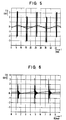
Figur 5- ein typisches Zündspannungsdiagramm;
Figur 6- ein typisches Diagramm von drei aufeinanderfolgenden Zündimpulsen.
- Figure 1
- an ignition circuit according to the prior art;
- Figure 2
- a first embodiment of the ignition circuit according to the invention;
- Figure 3
- a second embodiment of the ignition circuit according to the invention;
- Figure 4
- the second embodiment of the ignition circuit according to the invention, but with a differently connected return capacitor;
- Figure 5
- a typical ignition voltage diagram;
- Figure 6
- a typical diagram of three consecutive firing pulses.
Die in Figur 1 gezeigte Zündschaltung nach dem Stand der Technik ist mit zwei Anschlüssen 1,2 für das Wechselstromnetz versehen und dient zum Zünden einer Hochdruckmetalldampfentladungslampe 5. Eine Elektrode der Lampe 5 liegt am Netzanschluß 2. Die andere Elektrode der Lampe 5 ist mit einem Überlagerungszündspannungsgerät 4 verbunden. Dem Überlagerungszündspannungsgerät 4 ist eine Vorschaltinduktivität 3 vorgeschaltet, die von einer Drossel mit einer einzigen Wicklung gebildet ist. Die Vorschaltinduktivität 3 liegt einerseits am Wechselstromnetzanschluß 1 und ist andererseits mit einem Anschluß des Stoßkondensators 6 verbunden. Der andere Anschluß eines Stoßkondensators 6 ist mit einem Anschluß eines Zündhilfskondensators 7 verbunden. Der andere Anschluß des Zündhilfskondensators 7 ist mit dem Wechselstromnetzanschluß 2 verbunden. Dem Zündhilfskondensator 7 ist ein Widerstand 8 parrallel geschaltet, der die Einhaltung des gewünschten Betriebsspannungsbereiches und der gegebenen Grenzen für die Phasenlage der Zündimpulse gewährleistet. Der Verbindungspunkt zwischen dem Stoßkondensator 6 und dem Zündhilfskondensator 7 ist über eine Hochfrequenzspule 14 mit einem Anschluß eines Schalterelementes 9 verbunden. Dieses ist im vorliegenden Fall ein Sidac. Dieses Schalterelement ist normalerweise nicht-leitend. Es wird leitend, wenn die an ihm anliegende Spannung einen bestimmten Schwellspannungswert überschreitet. Das gilt in beiden Polaritätsrichtungen. Das Schalterelement 9 kann beispielsweise auch eine Vierschichtdiode sein. Der andere Anschluß des Schalterelementes 9 ist mit einem Anschluß 15 eines als Spartransformator geschalteten Impulstransformators 10 verbunden. Der andere Anschluß 16 des Impulstransformators 10 ist mit der Lampe 5 verbunden. Der Impulstransformator 10 ist mit einer Anzapfung 13 versehen, welche mit dem Verbindungspunkt zwischen der Vorschaltinduktivität 3 und dem Stoßkondensator 6 verbunden ist. Bei dem Impulstransformator 10 liegt die Primärwicklung zwischen dem einen Anschluß 15 und der Anzapfung 13. Die Sekundärwicklung liegt zwischen der Anzapfung 13 und dem anderen Anschluß 16. Anstelle des Spartransformators kann auch ein Transformator mit getrennter Primär- und Sekundärwicklung verwendet werden.The ignition circuit shown in FIG. 1 according to the prior art is provided with two
Die vorstehend beschriebene Zündschaltung kann für Hochdruckmetalldampfentladungslampen verwendet werden, welche eine Leistung von ca 150W aufnehmen.The ignition circuit described above can be used for high-pressure metal vapor discharge lamps which have a power of approximately 150W.
Die bekannte Schaltung funktioniert wie folgt: Wenn das Wechselstromnetz an die Anschlüsse 1 und 2 angeschaltet wird und beispielsweise eine positive Halbwelle beginnt, so werden der Stoßkondensator 6 und der Zündhilfskondensator 7 über die Vorschaltinduktivität 3 während der ansteigenden Phase der Halbwelle aufgeladen. Wenn die Spannung an dem Stoßkondensator 6 den von dem Schalterelement 9 vorgegebenen Spannungsschwellwert überschreitet, so schaltet das Schalterelement 9 durch, d.h. es wird schlagartig vom nicht-leitenden Zustand in den leitenden Zustand umgeschaltet. Dadurch entlädt sich der Stoßkondensator 6 über das Schalterelement 9. Dies hat zur Folge, daß an der Anzapfung 13 des Impulskondensators 12 ein Spannungsstoß entsteht, der sich der am Schaltungspunkt 16 liegenden Netzspannung überlagert und mehrere kV betragen kann. Dieser Spannungsstoß führt zur Ionisierung der Lampe 5. Gleichzeitig wird der aus der Vorschaltinduktivität 3 und dem Zündhilfskondensator 7 gebildete Reihenresonanzkreis angestoßen, mit der Folge, daß eine gedämpfte Schwingung entsteht. Diese liegt an der Primärwicklung 11 des Impulstransformators 10 an und wird hochtransformiert, so daß nach dem Spannungstoß an der Lampe 5 eine abklingende Hochfrequenzschwingung hoher Spannung anliegt. Die Resonanzfrequenz der aus der Vorschaltinduktivität 3 und dem ZÜndhilfskondensator 7 gebildeten Reihenresonanzschaltung ist so gewählt, daß zumindest die auf den Spannungsstoß folgende erste Halbwelle der abklingenden Schwingung auf die noch ionisierte Lampe 5 trifft, wenn die Lampe 5 nicht schon auf den Spannungsstoß hin gezündet hat. Mit dem Abklingen der Hochfrequenzschwingung unterhalb des Spannungsschwellwertes des Schalterelementes 9 wird dieses wieder nicht-leitend. Danach wiederholt sich dieser Vorgang, und zwar mindestens dreimal pro Netzhalbwelle. Dies wird von den Lampenherstellern für eine sichere Zündung der Lampe 5 vorgeschrieben, wobei der zeitliche Abstand der Zündimpulse nicht größer als 0,3ms sein darf. Nach Zündung der Lampe 5 begrenzt die Vorschaltinduktivität 3 den Lampenstrom auf den der Nennleistung von ca 150W entsprechenden Strom. Die Vorschaltinduktivität 3 bestimmt demnach den zeitlichen Abstand der Zündimpulse sowie die Frequenz der abklingenden Schwingung und dient außerdem zur Begrenzung des durch die Lampe 5 fließenden Stromes nach Zündung.The known circuit works as follows: If the AC network is connected to the
Die in den Figuren 2 bis 4 dargestellten Schaltungen dienen zur Zündung von Lampen 105,205 die eine geringere Leistung als die Lampe 5 in Figur 1 haben. Typisch sind dafür Lampen mit einer Leistung von 35 bzw. 70W. Solche Lampen müssen wegen ihrer geringeren Leistungsaufnahme auf einen entsprechend geringeren Strom begrenzt werden. Um dies zu gewährleisten hat die Zündschaltung gemäß Figur 2 eine Vorschaltinduktivität 103 die, wie bisher, von einer einzigen Drossel gebildet ist, welche jedoch neben einer ersten Drosselwicklung 104 eine weitere Drosselwicklung 108 aufweist. Beide Drosselwicklungen 104,108 sitzen auf dem gleichen Kern. Die erste Drosselwicklung 104 ist wie die in der bekannten Zündschaltung gemäß Figur 1 gezeigte die Vorschaltinduktivität 3 bildende einzige Drosselwicklung geschaltet. Die zweite Drosselwicklung 108 ist zwischen die Lampe 105 und den Anschluß 2 der Wechselstromquelle geschaltet. Sie ist außerdem von einem Rückschlußkondensator 106 überbrückt. Auf diese Weise bildet nur die erste Drosselwicklung 104 eine Reihenschaltung mit dem Stoßkondensator 6 und dem Zündhilfskondensator 7, mit der Folge, daß der zeitliche Abstand der Zündimpulse und die Resonanzfrequenz der von der ersten Drosselwicklung 104 und dem Zündhilfskondensator 7 gebildeten Reihenresonanzschaltung gegenüber den entsprechenden Werten der Schaltung nach Figur 1 weitgehend unverändert bleiben. Wenn die Lampe 105 dagegen gezündet hat, so liegt im Stromkreis der Lampe außer der ersten Drosselwicklung 104 auch die zweite Drosselwicklung 108 mit der Folge, daß der Lampenstrom auf einen entsprechend reduzierten Wert begrenzt wird.The circuits shown in FIGS. 2 to 4 serve to ignite
Die Figur 5 zeigt den zeitlichen Verlauf der am Punkt 16 der Zündschaltung gemäß Figur 2 entstehenden Zündspannung. Man erkennt, daß jeweils drei Zündimpulse pro Netzhalbwelle auftreten.FIG. 5 shows the time course of the ignition voltage generated at
Die Figur 6 ist unter Zeitdehnung der Figur 5 entstanden und zeigt drei während einer Netzhalbwelle aufeinanderfolgende Zündimpulse, wobei man erkennt, daß auf den ersten Spannungstoß eine abklingende Schwingung folgt.FIG. 6 was created while stretching the time of FIG. 5 and shows three ignition pulses in succession during a network half-wave, it being recognized that the first voltage surge is followed by a decaying oscillation.
Während bei der Zündschaltung nach Figur 2 zwei getrennte Wicklungen 104, 108 vorgesehen sind, die galvanisch voneinander getrennt sind, ist bei der Zündschaltung nach Figur 3 an der Vorschaltinduktivität 303 lediglich eine Anzapfung 209 vorgesehen, welche die Vorschaltinduktivität 203 in eine erste Drosselwicklung 204 und in eine zweite Drosselwicklung 208 unterteilt. Die beiden Drosselwicklungen 204,208 sind durch die Anzapfung 209 galvanisch miteinander verbunden. Die erste Wicklung 204 ist einerseits mit dem Netzanschluß 1 verbunden und andererseits über die Anzapfung 209 mit dem Stoßkondensator 6. Die zweite Wicklung 208 ist einerseits, wie vorstehend beschrieben, über die Anzapfung 209 mit dem Stoßkondensator 6 und andererseits mit der Anzapfung 13 des Impulstransformators 10 verbunden. Ferner ist der mit der Anzapfung 13 des Impulstransformators 10 verbundene Anschluß der zweiten Wicklung 208 über einen Rückschlußkondensator 206 mit dem anderen Netzanschluß 2 verbunden. Bei dieser Zündschaltung leigt mit dem Zündhilfskondensator 7 und dem Stoßkondensator 6 wiederum nur die erste Wicklung 204 der Vorschaltinduktivität 203 in Serie, wodurch, wie in Zusammenhang mit der Zündschaltung nach Figur 2 beschrieben der zeitliche Abstand zwischen den Zündimpulsen sowie die Resonanzfrequenz im Vergleich zu der bekannten Zündschaltung nach Figur 1 weitgehend unverändert bleiben. Wenn dagegen die Lampe 205 mit verringter Leistung gezündet hat, so liegen im Stromkreis der Lampe beide Wicklungen 204,208 in Serie mit der Folge, daß der Lampenstrom auf einen entsprechend verringerten Wert begrenzt wird.While two
Die Zündschaltung gemäß Figur 4 unterscheidet sich nur insofern von der Zündschaltung nach Figur 3 als die zweite Wicklung 208 der Vorschaltinduktivität 203 hier direkt von einem Rückschlußkondensator 210 überbrückt ist.The ignition circuit according to FIG. 4 differs from the ignition circuit according to FIG. 3 only in that the second winding 208 of the
Es sei noch darauf hingewiesen, daß anstelle der Rückschlußkondensatoren 106,206,210 in den Figuren 2 bis 4 auch eine Reihenschaltung aus einem Rückschlußkondensator und einem Widerstand oder statt dessen ein spannungsabhängiger Widerstand (VDR) verwendet werden kann.It should also be pointed out that instead of the
Claims (7)
- Ignition circuit for a high pressure metal vapour discharge lamp which is to be connected to an a.c. current source, preferably the a.c. mains, comprising a ballast inductance provided by a choke coil, a surge capacitor, a resonance capacitor, a switch element which, in at least one polarity direction, is conducting above a certain threshold voltage and is non-conducting below this threshold voltage, and having a pulse transformer, whereby the choke coil, the surge capacitor and the resonance capacitor form a first series circuit to be connected to the a.c. current source, whereby the switch element and the primary winding of the pulse transformer, connected in series with the switch element, are connected in parallel with the surge capacitor, and whereby the choke coil, the secondary winding of the pulse transformer and the lamp form a second series circuit to be connected to the a.c. current source,
characterised by,
a further choke coil (108, 208) connected in the second series circuit (104, 12, 105, 108 or 204, 208, 12, - 205). - Ignition circuit according to claim 1,
characterised in that,
the further choke coil (108, 208) has a common choke core with the first-mentioned choke coil (104, 204). - Ignition circuit according to claim 1 or 2,
characterised in that,
the two choke coils (104, 108) are electrically separated, and the further choke coil (108) is connected between the lamp (105) and the corresponding terminal (2) of the a.c. voltage source. - Ignition circuit according to claim 1 or 2,
characterised in that,
the two choke coils (204, 208) are electrically connected at one end or are parts of a tapped (13) autotransformer (10), and the further choke coil (208) is connected between the first-mentioned choke coil (204) and the secondary winding (12) of the pulse transformer (10). - Ignition circuit according to claim 3 or 4,
characterised in that,
the further choke coil (108, 208) is bridged by a feedback impedance (106, 210) which provides a low resistance for the high frequency arising as a result of the generated ignition pulses or prevents a falling voltage at the further choke coil (108, 210) from exceeding a certain voltage threshold value. - Ignition circuit according to claim 4,
characterised in that,
between the connection point (13) formed by the further choke coil (208) and the secondary winding (12) of the pulse transformer (10) and the terminal (2) of the of the a.c. mains connected with the lamp (205) there is a feedback impedance (206) which provides a low resistance for the high frequency arising as a result of the generated ignition pulses or prevents a falling voltage at the further choke coil (208) from exceeding a certain voltage threshold value. - Ignition circuit according to claim 5 or 6,
characterised in that,
the feedback impedance is formed by a capacitor (106, 206, 210) of a capacitor-resistance combination or a voltage dependent resistance.
Applications Claiming Priority (2)
| Application Number | Priority Date | Filing Date | Title |
|---|---|---|---|
| DE3736542 | 1987-10-28 | ||
| DE19873736542 DE3736542A1 (en) | 1987-10-28 | 1987-10-28 | IGNITION SWITCHING FOR A HIGH PRESSURE METAL STEAM DISCHARGE LAMP |
Publications (2)
| Publication Number | Publication Date |
|---|---|
| EP0314178A1 EP0314178A1 (en) | 1989-05-03 |
| EP0314178B1 true EP0314178B1 (en) | 1994-10-19 |
Family
ID=6339283
Family Applications (1)
| Application Number | Title | Priority Date | Filing Date |
|---|---|---|---|
| EP88118033A Expired - Lifetime EP0314178B1 (en) | 1987-10-28 | 1988-10-28 | Ignition circuit for high-pressure met2l vapour discharge lamps |
Country Status (3)
| Country | Link |
|---|---|
| EP (1) | EP0314178B1 (en) |
| AT (1) | ATE113157T1 (en) |
| DE (2) | DE3736542A1 (en) |
Families Citing this family (4)
| Publication number | Priority date | Publication date | Assignee | Title |
|---|---|---|---|---|
| DE4236403A1 (en) * | 1992-10-28 | 1994-07-07 | Tridonic Bauelemente Ges Mbh D | Ignition circuit for a high pressure metal vapor discharge lamp |
| DE19531622B4 (en) * | 1995-08-28 | 2011-01-13 | Tridonicatco Gmbh & Co. Kg | Ignition circuit for a high pressure gas discharge lamp |
| DE19531623B4 (en) * | 1995-08-28 | 2010-09-23 | Tridonicatco Gmbh & Co. Kg | Method and circuit arrangement for igniting a high-pressure gas discharge lamp |
| DE19544842A1 (en) * | 1995-12-01 | 1997-06-05 | Bosch Gmbh Robert | Input circuit for an ignition device of a high-pressure gas discharge lamp |
Family Cites Families (3)
| Publication number | Priority date | Publication date | Assignee | Title |
|---|---|---|---|---|
| GB824906A (en) * | 1957-10-15 | 1959-12-09 | Engelhard Ind Inc | Improvements in or relating to an operating circuit for electrical discharge lamps |
| US4187449A (en) * | 1978-05-08 | 1980-02-05 | General Electric Company | Discharge lamp operating circuit |
| US4538094A (en) * | 1983-08-12 | 1985-08-27 | Iota Engineering Co. | Lamp ballast with near unity power factor and low harmonic content |
-
1987
- 1987-10-28 DE DE19873736542 patent/DE3736542A1/en not_active Withdrawn
-
1988
- 1988-10-28 DE DE3851868T patent/DE3851868D1/en not_active Expired - Fee Related
- 1988-10-28 AT AT88118033T patent/ATE113157T1/en not_active IP Right Cessation
- 1988-10-28 EP EP88118033A patent/EP0314178B1/en not_active Expired - Lifetime
Also Published As
| Publication number | Publication date |
|---|---|
| DE3736542A1 (en) | 1989-05-11 |
| ATE113157T1 (en) | 1994-11-15 |
| DE3851868D1 (en) | 1994-11-24 |
| EP0314178A1 (en) | 1989-05-03 |
Similar Documents
| Publication | Publication Date | Title |
|---|---|---|
| EP1211794B1 (en) | Method for regulation of output current and/or output voltage of switched mode power supply | |
| DE3108547A1 (en) | "IGNITION SWITCH FOR A HIGH PRESSURE METAL STEAM DISCHARGE LAMP" | |
| DE3108548C2 (en) | Ignition circuit for a high pressure metal vapor discharge lamp | |
| DE3333768A1 (en) | DEVICE FOR LIMITING AC FLOWS | |
| EP0116275A2 (en) | Reactive power compensator | |
| EP0868115B1 (en) | Circuit for ignition of a HID lamp | |
| DE69816950T2 (en) | CIRCUIT | |
| DE2758227C3 (en) | dv / dt protection circuit arrangement for a GTO thyristor | |
| DE4330859A1 (en) | Electronic ballast for a discharge lamp | |
| EP1058488B1 (en) | Ignition circuit for a lamp | |
| WO1998053647A1 (en) | Ignition device for a discharge lamp and method for igniting a discharge lamp | |
| EP0314178B1 (en) | Ignition circuit for high-pressure met2l vapour discharge lamps | |
| DE3204449C2 (en) | ||
| EP0381083A1 (en) | Starting circuit for a high-pressure metal vapour discharge lamp connected to an AC source by a ballast inductor | |
| EP0178735B1 (en) | Circuit arrangement for the ignition and operation of gas discharge lamps | |
| EP0212740A2 (en) | Apparatus for starting and operating gas discharge lamps | |
| EP0155729B1 (en) | Circuit device for the ac operation of high-pressure discharge lamps | |
| EP0595333B1 (en) | Starting circuit for a high pressure metal vapor discharge lamp | |
| DE2604914C3 (en) | Circuit arrangement for igniting and operating a discharge lamp | |
| DE60117764T2 (en) | IGNITION DEVICE WITH INTERFERENCE CAPACITY SUPPRESSOR | |
| DE69514182T2 (en) | CIRCUIT | |
| EP0599887B1 (en) | Device for operating a gas-discharge lamp | |
| EP2140735B1 (en) | Circuit configuration for starting and operating at least one discharge lamp | |
| EP0213354A1 (en) | Spark-over protection device in a transmitter circuit | |
| DE3339814A1 (en) | Starting circuit for a high-pressure metal-vapour discharge lamp |
Legal Events
| Date | Code | Title | Description |
|---|---|---|---|
| PUAI | Public reference made under article 153(3) epc to a published international application that has entered the european phase |
Free format text: ORIGINAL CODE: 0009012 |
|
| AK | Designated contracting states |
Kind code of ref document: A1 Designated state(s): AT CH DE FR GB IT LI |
|
| 17P | Request for examination filed |
Effective date: 19891031 |
|
| 17Q | First examination report despatched |
Effective date: 19921214 |
|
| GRAA | (expected) grant |
Free format text: ORIGINAL CODE: 0009210 |
|
| AK | Designated contracting states |
Kind code of ref document: B1 Designated state(s): AT CH DE FR GB IT LI |
|
| REF | Corresponds to: |
Ref document number: 113157 Country of ref document: AT Date of ref document: 19941115 Kind code of ref document: T |
|
| REF | Corresponds to: |
Ref document number: 3851868 Country of ref document: DE Date of ref document: 19941124 |
|
| ET | Fr: translation filed | ||
| ITF | It: translation for a ep patent filed |
Owner name: JACOBACCI CASETTA & PERANI S.P.A. |
|
| GBT | Gb: translation of ep patent filed (gb section 77(6)(a)/1977) |
Effective date: 19950124 |
|
| PLBE | No opposition filed within time limit |
Free format text: ORIGINAL CODE: 0009261 |
|
| STAA | Information on the status of an ep patent application or granted ep patent |
Free format text: STATUS: NO OPPOSITION FILED WITHIN TIME LIMIT |
|
| 26N | No opposition filed | ||
| PGFP | Annual fee paid to national office [announced via postgrant information from national office to epo] |
Ref country code: GB Payment date: 20000925 Year of fee payment: 13 |
|
| PGFP | Annual fee paid to national office [announced via postgrant information from national office to epo] |
Ref country code: FR Payment date: 20001017 Year of fee payment: 13 |
|
| PGFP | Annual fee paid to national office [announced via postgrant information from national office to epo] |
Ref country code: CH Payment date: 20001023 Year of fee payment: 13 Ref country code: AT Payment date: 20001023 Year of fee payment: 13 |
|
| PGFP | Annual fee paid to national office [announced via postgrant information from national office to epo] |
Ref country code: DE Payment date: 20001221 Year of fee payment: 13 |
|
| PG25 | Lapsed in a contracting state [announced via postgrant information from national office to epo] |
Ref country code: GB Free format text: LAPSE BECAUSE OF NON-PAYMENT OF DUE FEES Effective date: 20011028 Ref country code: AT Free format text: LAPSE BECAUSE OF NON-PAYMENT OF DUE FEES Effective date: 20011028 |
|
| PG25 | Lapsed in a contracting state [announced via postgrant information from national office to epo] |
Ref country code: LI Free format text: LAPSE BECAUSE OF NON-PAYMENT OF DUE FEES Effective date: 20011031 Ref country code: CH Free format text: LAPSE BECAUSE OF NON-PAYMENT OF DUE FEES Effective date: 20011031 |
|
| REG | Reference to a national code |
Ref country code: GB Ref legal event code: IF02 |
|
| REG | Reference to a national code |
Ref country code: CH Ref legal event code: PL |
|
| GBPC | Gb: european patent ceased through non-payment of renewal fee |
Effective date: 20011028 |
|
| PG25 | Lapsed in a contracting state [announced via postgrant information from national office to epo] |
Ref country code: FR Free format text: LAPSE BECAUSE OF NON-PAYMENT OF DUE FEES Effective date: 20020628 |
|
| PG25 | Lapsed in a contracting state [announced via postgrant information from national office to epo] |
Ref country code: DE Free format text: LAPSE BECAUSE OF NON-PAYMENT OF DUE FEES Effective date: 20020702 |
|
| REG | Reference to a national code |
Ref country code: FR Ref legal event code: ST |
|
| PG25 | Lapsed in a contracting state [announced via postgrant information from national office to epo] |
Ref country code: IT Free format text: LAPSE BECAUSE OF NON-PAYMENT OF DUE FEES;WARNING: LAPSES OF ITALIAN PATENTS WITH EFFECTIVE DATE BEFORE 2007 MAY HAVE OCCURRED AT ANY TIME BEFORE 2007. THE CORRECT EFFECTIVE DATE MAY BE DIFFERENT FROM THE ONE RECORDED. Effective date: 20051028 |