EP0312362B1 - Dispositif d'enregistrement et de reproduction magnétique - Google Patents
Dispositif d'enregistrement et de reproduction magnétique Download PDFInfo
- Publication number
- EP0312362B1 EP0312362B1 EP88309611A EP88309611A EP0312362B1 EP 0312362 B1 EP0312362 B1 EP 0312362B1 EP 88309611 A EP88309611 A EP 88309611A EP 88309611 A EP88309611 A EP 88309611A EP 0312362 B1 EP0312362 B1 EP 0312362B1
- Authority
- EP
- European Patent Office
- Prior art keywords
- head
- heads
- signal
- track
- magnetic
- Prior art date
- Legal status (The legal status is an assumption and is not a legal conclusion. Google has not performed a legal analysis and makes no representation as to the accuracy of the status listed.)
- Expired - Lifetime
Links
Images


Classifications
-
- G—PHYSICS
- G11—INFORMATION STORAGE
- G11B—INFORMATION STORAGE BASED ON RELATIVE MOVEMENT BETWEEN RECORD CARRIER AND TRANSDUCER
- G11B20/00—Signal processing not specific to the method of recording or reproducing; Circuits therefor
- G11B20/02—Analogue recording or reproducing
- G11B20/06—Angle-modulation recording or reproducing
-
- H—ELECTRICITY
- H04—ELECTRIC COMMUNICATION TECHNIQUE
- H04N—PICTORIAL COMMUNICATION, e.g. TELEVISION
- H04N5/00—Details of television systems
- H04N5/76—Television signal recording
- H04N5/78—Television signal recording using magnetic recording
- H04N5/782—Television signal recording using magnetic recording on tape
- H04N5/7824—Television signal recording using magnetic recording on tape with rotating magnetic heads
- H04N5/7826—Television signal recording using magnetic recording on tape with rotating magnetic heads involving helical scanning of the magnetic tape
-
- H—ELECTRICITY
- H04—ELECTRIC COMMUNICATION TECHNIQUE
- H04N—PICTORIAL COMMUNICATION, e.g. TELEVISION
- H04N5/00—Details of television systems
- H04N5/76—Television signal recording
- H04N5/91—Television signal processing therefor
- H04N5/92—Transformation of the television signal for recording, e.g. modulation, frequency changing; Inverse transformation for playback
- H04N5/928—Transformation of the television signal for recording, e.g. modulation, frequency changing; Inverse transformation for playback the sound signal being pulse code modulated and recorded in time division multiplex with the modulated video signal
-
- H—ELECTRICITY
- H04—ELECTRIC COMMUNICATION TECHNIQUE
- H04N—PICTORIAL COMMUNICATION, e.g. TELEVISION
- H04N9/00—Details of colour television systems
- H04N9/79—Processing of colour television signals in connection with recording
- H04N9/80—Transformation of the television signal for recording, e.g. modulation, frequency changing; Inverse transformation for playback
- H04N9/82—Transformation of the television signal for recording, e.g. modulation, frequency changing; Inverse transformation for playback the individual colour picture signal components being recorded simultaneously only
- H04N9/8205—Transformation of the television signal for recording, e.g. modulation, frequency changing; Inverse transformation for playback the individual colour picture signal components being recorded simultaneously only involving the multiplexing of an additional signal and the colour video signal
- H04N9/8211—Transformation of the television signal for recording, e.g. modulation, frequency changing; Inverse transformation for playback the individual colour picture signal components being recorded simultaneously only involving the multiplexing of an additional signal and the colour video signal the additional signal being a sound signal
- H04N9/8216—Transformation of the television signal for recording, e.g. modulation, frequency changing; Inverse transformation for playback the individual colour picture signal components being recorded simultaneously only involving the multiplexing of an additional signal and the colour video signal the additional signal being a sound signal using time division multiplex
Definitions
- This invention generally relates to a magnetic recording and reproducing apparatus such as a video tape recorder (VTR).
- VTR video tape recorder
- This invention specifically relates to a VTR designed so that an audio signal is recorded on an extended portion of a video signal recording track.
- an audio signal is converted into a corresponding digital signal which is recorded on and reproduced from a magnetic tape.
- the digitization of the audio signal aims at a high quality of reproduced sounds.
- the density of recording of an audio signal tends to be inadequate to high fidelity.
- EP-A-0090582 describes an apparatus where tracks are recorded onto a record medium, each track being divided into at least two sections along the length of the track. A video signal is recorded onto at least one of these sections and a digitised audio signal is recorded onto another section.
- EP-A-0206752 describes a similar apparatus with a plurality of heads mounted on a rotary drum, these heads recording the signals.
- an apparatus comprising:
- a prior art VTR includes stereo audio input terminals 1L and 1R receiving a left channel audio signal and a right channel audio signal respectively.
- An audio signal record processing circuit 2 samples the input audio signals and processes the sampled signals through various steps such as analog-to-digital conversion, time division multiplexing, and time base compression.
- an output signal from the audio signal record processing circuit 2 is transmitted to magnetic heads 21 and 22 via an audio recording amplifier 3, and switches 6 and 14 before being recorded on a magnetic tape 40.
- the prior art VTR includes a video input terminal 7 receiving a video signal.
- a video signal record processing circuit 8 processes the input video signal through various steps such as a step of separating the input video signal into a luminance signal and a color signal, a frequency modulation of the luminance signal, a frequency down conversion of the color signal, and a step of combining the processed luminance signal and the processed color signal into a processed video signal.
- an output signal from the video signal record processing circuit 8 is transmitted to the magnetic heads 21 and 22 via a video recording amplifier 9, and the switches 6 and 14 before being recorded on the magnetic tape 40.
- the magnetic heads 21 and 22 are mounted on a rotary drum 23.
- the magnetic heads 21 and 22 are mutually spaced by an angle of 180° with respect to the rotary drum 23.
- the magnetic tape 40 is obliquely wound on a part of the circumference of the rotary drum 23 which corresponds to a predetermined tape winding angle greater than 180°, for example, which corresponds to 216°.
- the tape winding angle is divided into a standard part Vs equal to 180° and an additional part Va equal to 36° for example.
- the phase of rotation of the rotary drum 23 is sensed by an angular position detector 24.
- a head switch pulse generation circuit 20 outputs a control pulse signal to the switch 6 in response to an output signal from the angular position detector 24.
- the switch 6 changes between a first state and a second state in accordance with the control pulse signal.
- the switch 6 connects the magnetic heads 21 and 22 to the video recording amplifier 9 and the audio recording amplifier 3 respectively.
- the switch 6 assumes the second state, the switch 6 reverses the connection so that the magnetic heads 21 and 22 are connected to the audio recording amplifier 3 and the video recording amplifier 9 respectively.
- the left channel audio signal and the right channel audio signal take waveforms as shown by Figs. 2(A) and 2(B) respectively.
- the audio signal record processing circuit 2 derives a digital audio signal from the two channel analog audio signals. As shown by Fig. 2(C), the digital audio signal has information blocks A1, A2, A3, ... time compressed and spaced at equal intervals.
- the video signal takes a waveform as shown by Fig. 2(D).
- the video signal includes segments P1, P2, P3, ... spaced at equal intervals.
- the control pulse signal applied to the switch 6 takes a waveform as shown by Fig. 2(G).
- the switch 6 changes the connections among the magnetic heads 21 and 22, and the recording amplifiers 3 and 9 in response to the control pulse signal so that alternate audio signal blocks A1, A3, A5, ... and alternate video signal segments P1, P3, P5, ... are sequentially transmitted to one of the magnetic heads 21 and 22 as shown by Fig. 2(E) and that alternate audio signal blocks A2, A4, A6, ... and alternate video signal segments P2, P4, P6, ... are sequentially transmitted to the other magnetic head as shown by Fig. 2(F).
- Video signal segments P1, P2, P3, ... are recorded on the magnetic tape 40 when the magnetic heads 21 and 22 scan portions of the magnetic tape 40 which correspond to the standard part Vs of the tape wound angle, that is, an angle of 180° with respect to the rotary drum 23.
- Audio signal blocks A1, A2, A3, ... are recorded on the magnetic tape 40 when the magnetic heads 21 and 22 scan portions of the magnetic tape 40 which correspond to the additional part Va of the tape winding angle, that is, an angle of, for example, 36° with respect to the rotary drum 23.
- video signal segments P1, P2, P3, ... and audio signal blocks A1, A2, A3, ... are sequentially paired and recorded along respective inclined tracks 41 on the magnetic tape 40.
- Video signal segments P1, P2, P3, ... are recorded in upper portions of tracks.
- Audio signal blocks A1, A2, A3, ... are recorded in lower portions of tracks. In each of tracks, an audio signal block is recorded before a video signal segment is recorded with respect to the head scanning.
- the magnetic heads 21 and 22 reproduce video and audio signals from the magnetic tape 40.
- the reproduced video and audio signals are transmitted to a switch 17 via the switch 14 and reproducing amplifiers 15 and 15A.
- the head switch pulse generation circuit 20 outputs a control pulse signal to the switch 17 in response to the output signal from the angular position detector 24.
- the switch 17 is changed in accordance with the control pulse signal so that the reproduced audio signal and the reproduced video signal can be separated and supplied to an audio signal reproduction processing circuit 4 and a video signal reproduction processing circuit 18 respectively.
- the audio signal reproduction processing circuit 4 derives a left channel audio signal and a right channel audio signal from the reproduced audio signal through signal processing opposite to the signal processing in the audio signal record processing circuit 2.
- the left channel audio signal and the right channel audio signal are transmitted from the audio signal reproduction processing circuit 4 to audio output terminals 5L and 5R respectively.
- the video signal reproduction processing circuit 18 separates the reproduced video signal into a frequency modulated luminance signal and a down coverted color signal.
- the frequency modulated luminance signal is demodulated while the down converted color signal is subjected to frequency up conversion, and the resulting luminance and color signals are combined into a video signal.
- the video signal is transmitted from the video signal reproduction processing circuit 18 to a video output terminal 19.
- an audio signal is recorded in audio tracks extending along extended portions of respective video tracks.
- An example of such configuration is disclosed in the Japanese laid-open patent application 240784-1986. Since the recording of the audio signal into the magnetic tape is performed when the magnetic heads 21 and 22 scan portions of the magnetic tape 40 which correspond to the additional part Va of the tape winding angle, the available track area for the audio signal is considerably limited and the density of recording of the audio signal tends to be inadequate to high fidelity when a total available track area for video and audio is given.
- Fig. 4 shows a magnetic recording and reproducing apparatus according to a first embodiment of this invention.
- a right channel analog audio signal and a left channel analog audio signal are inputted into an audio signal record processing circuit 2 via input terminals 1R and 1L.
- the audio signal record processing circuit 2 includes a combination of an analog-to-digital (A/D) converter 405, a random access memory (RAM) 407, a format encoder 408, and a modulator 409.
- the input two channel analog audio signals are transmitted to the A/D converter 405 via low pass filters (LPFs) 403 and 404.
- LPFs low pass filters
- the two channel analog audio signals are processed through time division multiplexing and are converted into a corresponding digital signal.
- the digital audio signal which represents audio data is outputted to a data bus 406.
- the audio data are written into the RAM 407 via the data bus 406.
- addresses outputted from an address generator are designated so that the audio data can be interleaved.
- the audio data are transferred from the RAM 407 to the format encoder 408 via the data bus 406.
- the format encoder 408 generates error correction and detection codes in correspondence with the audio data. It should be noted that the encoding format of the encoder 408 is one of the industrial standards.
- the error correction and detection codes are outputted to the data bus 406 and are written into storage locations of the RAM 407 other than storage locations holding the audio data.
- Audio data corresponding one field of a video signal, and related error correction and detection codes are read out from the RAM 407 and are transmitted to the modulator 409 via the data bus 406.
- the speed of the data readout from the RAM 407 is set equal to the speed of the signal recording on a magnetic tape 40 (see Fig. 7) so that the audio data and the error correction and detection codes can be compressively recorded into the magnetic tape.
- the digital audio signal which contains the audio data and the error correction and detection codes, is modulated into a PCM audio signal by the device 409 so as to match the record and reproduction characteristics of rotary transformers 211A-214A, magnetic heads 211-214, and the magnetic tape 40 (see Fig. 7).
- the PCM audio signal is outputted from the modulator 409 to switches 410 and 411 via a recording amplifier 409A.
- the switches 410 and 411 serve to change a recording mode and a playback mode.
- switches 412-415 are connected to the magnetic heads 211-214 via the rotary transformers 211A-214A respectively.
- the switches 412-415 are changed by control signals SEL1-SEL4 outputted from a signal change control section 51.
- the switches 412-415 are changed at timings as shown in Figs. 8(A), 8(D), and 8(E) so that the PCM audio signal is sequentially supplied to the magnetic heads 211-214 via the rotary transformers 211A-214A.
- the PCM audio signal is recorded on the magnetic tape 40 (see Fig. 7) via the magnetic heads 211-214.
- a conventional video signal processing circuit 30 receives a video signal through a terminal 30A and outputs the video signal to two of the switches 412-415.
- the switches 412-415 select the PCM audio signals and the video signals and pass the selected signals to the magnetic heads 211-214 via the rotary transformers 211A-214A in response to the control signals SEL1-SEL4 from the signal change control section 51. Accordingly, the video signal and the PCM audio signals are recorded on the magnetic tape 40 (see Fig. 7).
- the control signals SEL1-SEL4 to the switches 412-415 are generated by the signal change control section 51 in accordance with PCM head switching pulse signals SW1 and SW2 of Figs. 8(D) and 8(E) and with a video head switching pulse signal of Fig. 8(A) which is outputted from the video signal processing circuit 30.
- PCM audio signals are reproduced from the magnetic tape 40 (see Fig. 7) via the magnetic heads 211-214.
- the reproduced PCM audio signals are selected by the switches 412-415 at timings as shown in Figs. 8(A), 8(D), and 8(E) and are sequentially transmitted to a demodulator 416 within an audio signal reproduction processing circuit 4 via the switches 410 and 411 and reproducing amplifiers 416A and 416B.
- contacts "PB" are selected in the switches 410 and 411 during the playback mode of operation.
- the reproduced PCM audio signals are demodulated by the device 416 into a digital audio signal containing audio data and related error correction and detection codes.
- the digital audio signal from the demodulator 416 is written into a memory 417.
- Reference clocks fed to the memory 417 are produced by a combination of a PLL (phase locked loop) circuit 418 and a clock generation circuit 419 on the basis of a horizontal sync signal fH in a video signal which is simultaneously reproduced via the video signal processing circuit 30.
- PLL phase locked loop
- the audio data and the error correction and detection codes are transferred from the memory 417 to a RAM 421 via a data bus 420.
- An error correction circuit 422 checks the audio data in the RAM 421 and corrects an error or errors in the audio data by referring to the error correction and detection codes. In this way, the audio data in the RAM 421 are substantially cleared of errors. However, it should be noted that some errors can not be corrected by the error correction circuit 422. Such errors are corrected by a correction circuit 423 through an average value interpolation or other known processes.
- the clean audio data are transferred from the RAM 421 to the correction circuit 423 via the data bus 420.
- the correction circuit 423 After the correction circuit 423 begins the data time base back to the original data time base and separates the audio data into two parts corresponding to the right channel and the left channel respectively, the correction circuit 423 supplies the audio data to a digital-to-analog (D/A) converter 424.
- the audio data are transformed by the D/A converter 424 into corresponding two channel analog audio signals, which are transmitted to audio output terminals 5R and 5L via low pass filters (LPF) 425 and 426 respectively.
- LPF low pass filters
- the low pass filters 425 and 426 remove unnecessary high frequency components from the analog audio signals.
- video signals are reproduced from the magnetic tape 40 (see Fig. 7) via two of the magnetic heads 211-214.
- the reproduced video signals are transmitted via two of the switches 412-415 to the video signal processing circuit 30.
- the video signal processing circuit 30 derives a composite video signal from the reproduced video signals.
- the video signal processing circuit 30 extracts a horizontal sync signal from the video signals and outputs the extracted horizontal sync signal to the PLL circuit 418.
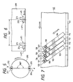
- the magnetic heads 211-214 are mounted on a rotary drum 200 designed to rotate in a direction C.
- the magnetic tape 40 (see Fig. 7) is obliquely wound on a part of the circumference of the rotary drum 200 which corresponds to a predetermined tape winding angle greater than a standard tape winding angle.
- the predetermined tape winding angle is divided into a standard part corresponding to the standard tape winding angle and an additional part extending outward of the standard tape winding angle. When the standard tape winding angle is substantially equal to 180°, the additional part may be approximately 20° for example.
- the magnetic heads 211 and 212 are located near a point X of an intersection between a circumference and a diametrical line l with respect to the rotary drum 200.
- the magnetic heads 213 and 214 are located near a point Y of an opposite intersection between the circumference and the diametrical line l. Accordingly, the magnetic heads 211 and 212 are close to each other. The magnetic heads 213 and 214 are close to each other. The magnetic heads 211 and 213 are spaced by an angle of 180° with respect to the rotary drum 200. Similarly, the magnetic heads 212 and 214 are spaced by an angle of 180° with respect to the rotary drum 200.
- the magnetic heads 211, 212, 213, and 214 are designed for a first channel in a standard play (SP) mode, a second channel in a extended play (EP) mode, a second channel in the SP mode, and a first channel in the EP mode, respectively. As shown in Fig.
- the first channel SP head 211 and the first channel EP head 214 have azimuth angles of +6°.
- the second channel EP head 212 and the second channel SP head 213 have azimuth angles of -6°.
- the SP heads 211 and 213 have a standard width which is approximately twice the width of the EP heads 212 and 214.
- Lower edges of the magnetic heads 211-214 are essentially at a common height meaured along an axis of the rotary drum 200. It should be noted that, in Fig. 6, the arrow B denotes a head running direction.
- the arrangement of the rotary drum 200 and the magnetic heads 211-214 corresponds to the arrangement of a rotary drum and magnetic heads in a conventional VHS system, i.e. one of the industry standard systems.
- a control track 101 is formed along an edge of the magnetic tape 40.
- the control track holds a control signal which is used in tracking control during the playback mode of operation of the apparatus.
- the arrow A denotes a tape running direction
- the arrow B denotes a head scanning direction.
- inclined video tracks are formed by the SP heads 211 and 213 on the magnetic tape 40 in regions corresponding to the standard part of the predetermined tape winding angle.
- the reference numerals 111-114 denote some of these video tracks.
- Audio tracks are formed by the magnetic heads 211-214 on the magnetic tape 40 in regions corresponding to the additional part of the predetermined tape winding angle.
- the reference numerals 121-128 denote some of these audio tracks.
- a pair of audio tracks reside in an area extending along an extended portion of each of the video tracks.
- the SP head 211 forms the video track 111 and then leaves a narrow guard band 106. After the resulted formation of the guard band 106, the SP head 211 forms the audio track 121.
- the first channel or left channel PCM audio signal is recorded on the audio track 121.
- the width of the audio track 121 is equal to the width of the video track 111.
- the EP head 212 forms the audio track 122 on a half of the audio track 121 while overwriting a new PCM audio signal on the previously-recorded PCM audio signal.
- a total width of the audio tracks 121 and 122 is substantially maintained to be equal to the width of the video track 111.
- the SP head 213 forms the video track 112, a guard band 107, and the audio track 123.
- the EP head 214 forms the audio track 124 on a half of the audio track 123 while overwriting a new PCM audio signal on the previously-recorded PCM audio signal.
- a signal change control section 51 includes gates 51A-51D and an inverter 51E.
- First input terminals of the gates 51A and 51B are subjected to a video head switching pulse signal (see Fig. 8(A)) supplied from the video signal processing circuit 30.
- Second input terminals of the gates 51A and 51B are subjected to PCM head switching pulse signals SW1 and SW2 (see Figs. 8(D) and 8(E)) respectively.
- the gates 51A and 51B output the control signals SEL1 and SEL2 to the switches 412 and 413 respectively.
- the video head switching signal (see Fig. 8(A)) is also applied to an input terminal of the inverter 51E.
- First input terminals of the gates 51C and 51D are subjected to an output signal from the inverter 51E.
- Second input terminals of the gates 51C and 51D are subjected to the PCM head switching pulse signals SW1 and SW2 respectively.
- the gates 51C and 51D output the control signals SEL3 and SEL4 to the switches 414 and 415 respectively.
- the signal change control section 51 generates the control signals SEL1-SEL4 in accordance with the video head switching signal (see Fig. 8(A)) and the PCM head switching signals SW1 and SW2 (see Figs. 8(D) and 8(E)).
- a circuit for generating the PCM head switching pulse signals SW1 and SW2 includes delay devices 51P-51R and gates 51S and 51T.
- An output pulse signal from a known flip-flop (not shown), which is generated in response to drum pulses synchronous with rotation of the drum 200 (see Fig. 5), is applied to the delay devices 51P and 51Q and a first input terminal of the gate 51S.
- the device 51P delays the input pulse signal by a time equal to a period during which the PCM audio signal corresponding to a half of one field is recorded.
- An output signal from the delay device 51P is applied to a second input terminal of the gate 51S.
- the gate 51S outputs the PCM head switching pulse signal SW1 (see Fig. 8(D)).
- the device 51Q delays the input pulse signal by a time corresponding to a gap distance between the magnetic heads 211 and 212 or a gap distance between the magnetic heads 213 and 214.
- An output signal from the delay device 51Q is applied to the delay device 51R and a first input terminal of the gate 51T.
- the device 51R delays the input pulse signal by a time equal to a period during which the PCM audio signal corresponding to a half of one field is recorded.
- An output signal from the delay device 51R is applied to a second input terminal of the gate 51T.
- the gate 51T outputs the PCM head switching pulse signal SW2 (see Fig. 8(E)).
- an N-th field of the video signal shown in Fig. 8(B) is recorded via the first channel SP head 211 so that the video track 111 (see Fig. 7) is formed.
- an (N+1)-th field of the video signal of Fig. 8(B) is recorded via the second channel SP head 213 so that the video track 112 (see Fig. 7) is formed.
- the portion 300 of the audio signal which corresponds to the N-th field of the video signal, is compressed into portions 301a and 302a of the PCM audio signal.
- the portions 301a and 302a of the PCM audio signal are sequentially recorded via the magnetic heads 211 and 212 so that the audio tracks 121 and 122 (see Fig. 7) are sequentially formed.
- the timings of recording of the PCM audio signal portions 301a and 302a are determined by the timings of the PCM head switching pulses SW1 and SW2 respectively. Specifically, when both of the video head switching signal of Fig.
- the control signal SEL1 operates the switch 412 to pass the PCM audio signal portion 301a to the magnetic head 211 so that the PCM audio signal portion 301a is recorded via the mangetic head 211.
- the control signal SEL2 operates the switch 413 to pass the PCM audio signal portion 302a to the magnetic head 212 so that the PCM audio signal portion 302a is recorded via the mangetic head 212.
- an (N+2)-th field of the video signal is recorded by the first channel SP head 211 into a video track 113.
- the portion 310 of the audio signal which corresponds to the (N+1)-th field of the video signal, is compressed into portions 303a and 304a of the PCM audio signal.
- the portions 303a and 304a of the PCM audio signal are sequentially recorded via the magnetic heads 213 and 214 so that the audio tracks 123 and 124 (see Fig. 7) are formed.
- the timings of recording of the PCM audio signal portions 303a and 304a are determined by the timings of the PCM head switching pulses SW1 and SW2 respectively.
- the control signal SEL3 operates the switch 414 to pass the PCM audio signal portion 303a to the magnetic head 213 so that the PCM audio signal portion 303a is recorded via the mangetic head 213.
- the control signal SEL4 operates the switch 414 to pass the PCM audio signal portion 304a to the magnetic head 214 so that the PCM audio signal portion 304a is recorded via the mangetic head 214.
- activated magnetic heads are selected in accordance with the video head switching signal (see Fig. 8(A)) and the PCM heads switching signals SW1 and SW2 (see Figs. 8(D) and 8(E)) in a manner similar to the magnetic head selection during the standard-play recording mode of operation.
- portions 301b and 302b of a recorded PCM audio signal are sequentially reproduced via the magnetic heads 211 and 212 respectively.
- Fig. 8(A) the video head switching signal
- PCM heads switching signals SW1 and SW2 see Figs. 8(D) and 8(E)
- the audio data represented by the PCM audio signal portions 301b and 302b are subjected to the error detection and correction process.
- the error-corrected reproduced audio signal corresponding to the PCM audio signal portions 301b and 302b is outputted.
- subsequent portions 303b and 304b of the recorded PCM audio signal are sequentially reproduced via the magentic heads 213 and 214 respectively and are subjected to the error detection and correction process.
- the EP heads 212 and 214 are used in place of the SP heads 211 and 213. After the EP head 212 or 214 forms a video track, the same EP head records a PCM audio signal forming an audio track in a region extending from the video track. A single audio track is formed in a region extending from each video track.
- a double mode one of the long-play modes, is realized by transporting the magnetic tape 40 at a half of a standard mode tape speed.
- a three-times mode one of the long-play modes, is realized by transporting the magnetic tape 40 at one third of the standard mode tape speed. In the case of the three-times mode, although adjacent tracks contact side by side or overlap each other, azimuth angles of the adjacent tracks are different from each other so that degradation by crosstalk between the adjacent tracks caused in the reproduced signals remains within an allowable small degree.
- the first channel EP head 212 records an N-th field of a video signal and thus forms an N-th field video track.
- the second channel EP head 214 records an (N+1)-th field of the video signal and thus forms an (N+1)-th field video track.
- a portion 300 of an audio signal which corresponds to the N-th field video signal is compressed into a PCM audio signal 301.
- the first channel EP head 212 is still operating to record the PCM audio signal 301.
- the same EP head records the PCM audio signal 301 and thus forms an audio track in a region extending from the N-th field video track.
- the first channel EP head 212 records an (N+2)-th field of the video signal and thus forms an (N+2)-th field video track.
- a portion 310 of the audio signal which corresponds to the (N+1)-th field video signal is compressed into a PCM audio signal 303.
- the second channel EP head 214 is still operating to record the PCM audio signal 303.
- the same EP head records the PCM audio signal 303 and thus forms an audio track in a region extending from the (N+1)-th field video track.
- Such processes are periodically reiterated so that subsequent video tracks and audio tracks are similarly formed.
- timings of recording of the PCM audio signals are determined by second PCM head switching pulses SW2.
- a first PCM head switching signal SW1 is held at a low level state.
- the first channel EP head 212 reproduces a PCM audio signal 301b at a timing determined by the second PCM head switching signal SW2.
- the reproduced PCM audio signal 301b is processed by the demodulator 416 into corresponding data.
- the data are written into the memory 417.
- Reference clocks for the data writing into the memory 417 are generated by the combination of the PLL circuit 418 and the clock generator 419 on the basis of the horizontal sync signal fH in a video signal which is reproduced simultaneously with the reproduction of the PCM audio signal.
- the data are transferred from the memory 417 to the RAM 421. As shown in Figs.
- FIG. 11-13 A second embodiment of this invention will be described hereinafter with reference to Figs. 11-13.
- the second embodiment is similar to the embodiment of Figs. 4-10 except for the following design changes.
- audio tracks 121-124 are formed on a magnetic tape 40 before the formation of related video tracks 111-114 respectively so that the audio tracks 121-124 extend in regions lower than the video tracks 111-114.
- a signal change control section 52 corresponding to the signal change control section 51 of Fig. 4 includes gates 52A-52D and an inverter 52E.
- First input terminals of the gates 52A and 52D and an input terminal of the inverter 52E are subjected to a video head switching signal (see Fig. 13(A)) supplied from a video signal processing circuit 30 (see Fig. 4).
- a second input terminal of the gate 52A is subjected to a PCM head switching signal SW1 (see Fig. 13(D)).
- the gate 52A outputs a control signal SEL1 to a switch 412 (see Fig. 4).
- a second input terminal of the gate 52D is subjected to a PCM head switching signal SW2 (see Fig.
- the gate 52D outputs a control signal SEL4 to a switch 415 (see Fig. 4).
- An output signal from the inverter 52E is applied to first input terminals of the gates 52B and 52C.
- a second input terminal of the gate 52B is subjected to the PCM head switching signal SW2 (see Fig. 13(E)).
- the gate 52B outputs a control signal SEL2 to a switch 413 (see Fig. 4).
- a second input terminal of the gate 52C is subjected to the PCM head switching signal SW1 (see Fig. 13(D)).
- the gate 52C outputs a control signal SEL3 to a switch 414 (see Fig. 4).
- an audio signal 300 of Fig. 13(C) is subjected to signal processing such as analog-to-digital conversion, frequency compression, and time division multiplexing, so that the audio signal 300 is separated and converted into PCM audio signals 301a and 302a of Figs. 13(F) and 13(G).
- signal processing such as analog-to-digital conversion, frequency compression, and time division multiplexing
- the PCM audio signal 301a is recorded on the audio track 121 via a magnetic head 211 (see Figs. 4-6) of a standard width
- the PCM audio signal 302a is written over a portion of the previously-formed audio track 121 of the PCM audio signal 301a and is thereby recorded on the newly-formed audio track 122 via a magnetic head 212 (see Figs.
- the recording of the PCM audio signal 302a is followed by a formation of a guard band 106.
- a video signal N of Fig. 13(B) is recorded via the magnetic head 211 so that the video track 111 is formed.
- a PCM audio signal 304a (see Fig. 13(G) is written over a portion of the previously-formed audio track 123 of the recored PCM audio signal 303a and is thereby recorded on the newly-formed audio track 124 via a magnetic head 214 (see Figs. 4-6) of a small width.
- the recording of the PCM audio signal 304a is followed by a formation of a guard band 107. After the formation of the guard band 107, a video signal N+1 of Fig. 13(B) is recorded via the magnetic head 213 so that the video track 112 is formed.
- activated magnetic heads are selected in accordance with the video head switching signal (see Fig. 13(A)) and the PCM heads switching signals SW1 and SW2 (see Figs. 13(D) and 13(E)) in a manner similar to the magnetic head selection during the standard-play recording mode of operation.
- portions 301b and 302b of a recorded PCM audio signal are sequentially reproduced via the magnetic heads 211 and 212 respectively.
- Fig. 13(A) the video head switching signal
- PCM heads switching signals SW1 and SW2 see Figs. 13(D) and 13(E)
- the audio data represented by the PCM audio signal portions 301b and 302b are subjected to the error detection and correction process.
- the accurate reproduced audio signal corresponding to the PCM audio signal portions 301b and 302b is outputted.
- subsequent portions 303b and 304b of the recorded PCM audio signal are sequentially reproduced via the magentic heads 213 and 214 respectively and are subjected to the error detection and correction process.
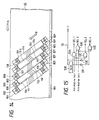
- FIG. 14-16 A third embodiment of this invention will be described hereinafter with reference to Figs. 14-16.
- the third embodiment is similar to the embodiment of Figs. 4-10 except for the following design changes.
- audio tracks 821-832 are formed in regions above and below video tracks 111-114.
- an arrangement of magnetic heads 211-214 (see Figs. 4-6) is modified as follows.
- the angular spacing between the magnetic heads 211 and 212 is chosen to correspond to a time which is required to form the upper and lower audio tracks 821 and 822 by the preceding magnetic head 211 prior to the formation of the audio tracks 823 and 824 by the magnetic head 212, that is, which is the sum of the periods of the formation of the audio tracks 821 and 822.
- the angular spacing between the magnetic heads 213 and 214 is designed similarly.
- a signal change control section 53 corresponding to the signal change control section 51 of Fig. 4 includes gates 53A-53D, inverters 53E and 53F, and a delay circuit 53G.
- a first input terminal of the gate 53A and input terminals of the gate 53E and the delay circuit 53G are subjected to a video head switching signal (see Fig. 16(A)) supplied from a video signal processing circuit 30 (see Fig. 4).
- a second input terminal of the gate 53A is subjected to a PCM head switching signal SW1 (see Fig. 16(D)).
- the gate 53A outputs a control signaL SEL1 to a switch 412 (see Fig. 4).
- An output signal see Fig.
- 16(A′) from the delay circuit 53G is applied to an input terminal of the inverter 53F and a first input terminal of the gate 53B.
- a second input terminal of the gate 53B is subjected to a PCM head switching signal SW2 (see Fig. 16(E)).
- the gate 53B outputs a control signal SEL2 to a switch 413 (see Fig. 4).
- An output signal from the inverter 53E is applied to a first input terminal of the gate 53C.
- a second input terminal of the gate 53C is subjected to the PCM head switching signal SW1 (see Fig. 16(D)).
- the gate 53C outputs a control signal SEL3 to a switch 414 (see Fig. 4).
- An output signal from the inverter 53F is applied to a first input terminal of the gate 53D.
- a second input terminal of the gate 53D is subjected to the PCM head switching signal SW2 (see Fig. 16(E)).
- the gate 53D outputs a control signal SEL4 to a switch 415 (see Fig. 4).
- an audio signal 300 of Fig. 16(C) is subjected to signal processing such as analog-to-digital conversion, frequency compression, and time division multiplexing, so that the audio signal 300 is separated and converted into PCM audio signals 901-904 of Figs. 16(F) and 16(G).
- signal processing such as analog-to-digital conversion, frequency compression, and time division multiplexing, so that the audio signal 300 is separated and converted into PCM audio signals 901-904 of Figs. 16(F) and 16(G).
- the PCM audio signal 902 is recorded on the audio track 822 via the magnetic head 213 (see Figs. 4-6) of a standard width.
- the PCM audio signal 903 is written over a portion of the previously-formed audio track 821 and is recorded on the newly-formed audio track 823 by the magnetic head 212 (see Figs. 4-6) of a small width.
- the PCM audio signal 904 is written over a portion of the previously-formed audio track 822 and is recorded on the newly-formed audio track 824 by the magnetic head 214 (see Figs. 4-6) of a small width.
- a lower guard band 106 is formed and a video signal N of Fig. 16(B) starts to be recorded via the magnetic head 211.
- the video track 111 is formed as the recording of the video signal N of Fig. 16(B) is performed.
- the PCM audio signal 906 is recorded on the audio track 826 via the magnetic head 211 (see Figs. 4-6). Subsequently, the PCM audio signal 907 is written over a portion of the previously-formed audio track 825 and is recorded on the newly-formed audio track 827 by the magnetic head 214 (see Figs. 4-6). After the formation of the audio track 827, the PCM audio signal 908 is written over a portion of the previously-formed audio track 826 and is recorded on the newly-formed audio track 828 by the magnetic head 212 (see Figs. 4-6).
- a lower guard band 107 is formed and a video signal N+1 of Fig. 16(B) starts to be recorded via the magnetic head 213.
- the video track 112 is formed.
- activated magnetic heads are selected in accordance with the video head switching signal (see Fig. 16(A)), the delayed video head switching signal (see Fig. 16(A′)), and the PCM head switching signals SW1 and SW2 (see Figs. 16(D) and 16(E)) in a manner similar to the magnetic head selection during the standard-play recording mode of operation.
- portions 891 and 892 of a recorded PCM audio signal are sequentially reproduced via the magnetic heads 211 and 213 respectively.
- portions 893 and 894 of the recorded PCM audio signal are sequentially reproduced via the magnetic heads 212 and 214 respectively.
- Fig. 16(F) portions 891 and 892 of a recorded PCM audio signal are sequentially reproduced via the magnetic heads 211 and 213 respectively.
- portions 893 and 894 of the recorded PCM audio signal are sequentially reproduced via the magnetic heads 212 and 214 respectively.
- the audio data represented by the PCM audio signal portions 891-894 are subjected to the error detection and correction process. As shown in Fig. 16(I), during a period subsequent to the period of the error detection and correction process, the accurate reproduced audio signal corresponding to the PCM audio signal portions 891-894 is outputted.
- a modulator 409 has two separate output terminals via which the PCM audio signals 901 and 902 are simultaneously outputted to the magnetic heads 211 and 213 respectively, and via which the PCM audio signals 903 and 904 are simultaneously outputted to the magnetic heads 212 and 214 respectively.
- the lower and upper audio tracks 821 and 822 are formed simultaneously and the lower and upper audio tracks 823 and 824 are formed simultaneously, and the angular spacing between the magnetic heads 211 and 212 and the angular spacing between the magnetic heads 213 and 214 can be made smaller.
- FIG. 17-21 A fourth embodiment of this invention will be described hereinafter with reference to Figs. 17-21.
- the fourth embodiment is similar to the embodiment of Figs. 4-10 except for the following design changes.
- magnetic heads 211-216 are mounted on a rotary drum 200 designed to rotate in a direction C.
- the magnetic heads 211 and 212 are located near a point Y of an intersection between a circumference and a diametrical line l with respect to the rotary drum 200.
- the magnetic heads 213 and 214 are located near a point X of an opposite intersection between the circumference and the diametrical line l. Accordingly, the magnetic heads 211 and 212 are close to each other.
- the magnetic heads 213 and 214 are close to each other.
- the magnetic heads 211 and 213 are spaced by an angle of 180° with respect to the rotary drum 200.
- the magnetic heads 212 and 214 are spaced by an angle of 180° with respect to the rotary drum 200.
- the magnetic heads 211, 212, 213, and 214 are assigned to a first channel in a standard play (SP) mode, a second channel in a extended play (EP) mode, a second channel in the SP mode, and a first channel in the EP mode, respectively where a group of heads for the first channel and another group of heads for the second channel are located oppsite each other to scan respective tracks alternately.
- the magnetic heads 215 and 216 precede the intersection points X and Y respectively by a predetermined angle ⁇ with respect to the rotary drum 200.
- the magnetic heads 215 and 216 are designed for audio recording. As shown in Fig.
- the position of lower edges of the EP heads 212 and 214 is essentially equal to the position of lower edges of the SP heads 211 and 213 in height measured along an axis of the rotary drum 200.
- the position of lower edges of the audio heads 215 and 216 is higher than the position of lower edges of the SP heads 211 and 213 by a predetermined distance "h" measured along the axis of the rotary drum 200.
- the distance "h” is chosen to essentially agree with the width of the SP heads 211 and 213.
- the first channel SP head 211 and the first channel EP head 214 have azimuth angles of +6°.
- the second channel EP head 212 and the second channel SP head 213 have azimuth angles of -6°.
- the audio heads 215 and 216 have azimuth angles of +30° and -30° respectively.
- This design of the rotary drum 200 and the magnetic heads 211-216 enables the apparatus to be compatible with one of the industry standard VTR systems.
- the SP heads 211 and 213 have a standard width and are normally used to record and reproduce a video signal in a standard mode.
- the EP heads 212 and 214 have approximately a half of the standard width and are normally used to record and reproduce a video signal in a long play mode such as a three-times play mode.
- the audio heads 215 and 216 are used to record an FM audio signal or a PCM audio signal into a deep layer of a magnetic tape.
- the arrangement of the rotary drum 200 and the magnetic heads 211-216 is generally similar to the arrangement of a rotary drum and magnetic heads in a conventional VTR. Accordingly, the conventional VTR drum and heads can basically be applicable to this embodiment.
- a "REC" contact is selected in a switch 410 so that a PCM audio signal is transmitted from a modulator 409 to switches 412-415 of a signal change section 49 via a recording amplifier 409A and the switch 410.
- the switches 412, 413, 414, and 415 are connected via rotary transformers (not shown) to the second channel audio head 216, the second channel EP head 212, the first channel audio head 215, and the first channel EP head 214 respectively.
- the switches 412-415 are changed in response to respective control signals SEL1-SEL4 supplied from a signal change control section 55.
- the PCM audio signal is sequentially supplied to the magnetic heads 212, 215, 214, and 216 through the switches 412-415.
- a "PB" contact is selected in the switch 410 so that reproduced PCM audio signals are transmitted from the magnetic heads 212, 215, 214, and 216 to a demodulator 416 via the switches 412-415 and a reproducing amplifier 416A.
- a conventional video signal processing circuit 30 is connected to the switches 413 and 415. During a long-play mode of operation of the apparatus, recording video signals or reproduced video signals are transmitted between the video signal processing circuit 30 and the EP heads 212 and 214 via the switches 413 and 415.
- the video signal processing circuit 30 is connected to the SP heads 211 and 213. During a standard-play mode of operation of the apparatus, recording video signals or reproduced video signals are transmitted between the video signal processing circuit 30 and the SP heads 211 and 213.
- a known FM audio circuit 60 is connected to the switches 412 and 414.
- FM audio signals are sequentially transmitted from the FM audio circuit 60 to the magnetic heads 215 and 216 via the switches 412 and 414.
- reproduced FM audio signals are sequentially transmitted from the magnetic heads 215 and 216 to the FM audio circuit 60 via the switches 412 and 414.
- the switches 413 and 415 select the PCM audio signals, the FM audio signals, and the video signals and pass the selected signals to the magnetic heads 216, 212, 215, and 214 in response to the control signals SEL1-SEL4 from the signal change control section 55. Accordingly, the PCM audio signals, the FM audio signals, and the video signals are selectively recorded on the magnetic tape 40 (see Fig. 20).
- the control signals SEL1-SEL4 are generated by the signal change control section 55 in accordance with a PCM head switching pulse signal SW (see Fig. 21(F)) supplied to the signal change control section 55 and a video head switching pulse signal of Fig.
- the video signal processing circuit 30 outputs video signals to the magnetic heads 211 and 213 via rotary transformers (not shown). These video signals are recorded on the magnetic tape 40 (see Fig. 20) via the magnetic heads 211 and 213.
- PCM audio signals are reproduced from the magnetic tape 40 (see Fig. 20) via the magnetic heads 216, 212, 215, and 214.
- the reproduced PCM audio signals are selected by the switches 412-415 at timings as shown in Figs. 21(A), 21(B), 21(F), and 21(J) and are sequentially transmitted to a demodulator 416 via a reproducing amplifier 416A.
- video signals are reproduced from the magnetic tape 40 (see Fig. 20) via the magnetic heads 211 and 213.
- the reproduced video signals are transmitted to the video signal processing circuit 30.
- the video signal processing circuit 30 derives a composite video signal from the reproduced video signals.
- the signal change control section 55 which corresponds to the circuit 51 of Fig. 4 includes gates 55A-55D and inverters 55E and 55F.
- First input terminals of the gates 55B and 55C and an input terminal of the inverter 55E are subjected to a video head switching pulse signal (see Fig. 21(A)) supplied from the video signal processing circuit 30.
- First input terminals of the gates 55A and 55D are subjected to an output signal from the inverter 55E.
- Second input terminals of the gates 55A and 55B and an input terminal of the inverter 55F are subjected to an audio head switching pulse signal (see Fig. 21(B)) supplied from the video signal processing circuit 30.
- FIG. 21(B) is advanced in phase relative to the video head switching signal of Fig. 21(A) by a value corresponding to the head spacing angle ⁇ .
- Second input terminals of the gates 55C and 55D are subjected to an output signal from the inverter 55F.
- Third input terminals of the gates 55A-55D are subjected to a PCM head switching pulse signal (see Fig. 21(F)) which is generated on the basis of drum pulses synchronous with the rotation of the rotary drum 200.
- the PCM head switching pulse signal of Fig. 21(F) can be generated by combining the audio head switching signals SW1 and SW2 of the embodiment of Figs. 4-10 through an OR gate and by modifying the delay times in the delay circuits.
- the gates 55A-55D output the control signals SEL1-SEL4 to the switches 412-415 respectively.
- the signal change control section 55 generates the control signals SEL1-SEL4 in accordance with the video head switching signal (see Fig. 21(A)), the audio head switching signal (see Fig. 21(B)), and the PCM head switching singal (see Fig. 21(F)).
- a control track 101 is formed along an edge of the magnetic tape 40.
- the control track holds a control signal which is used in tracking control during the playback mode of operation of the apparatus.
- the arrow A denotes a tape running direction
- the arrow B denotes a head scanning direction.
- inclined video tracks are formed on the magnetic tape 40 by the magnetic heads 211 and 213.
- the reference numerals 111-114 denote some of these video tracks.
- Audio tracks are formed on the magnetic tape 40 by the magnetic heads 212, 214, 215, and 216.
- the reference numerals 121-128 denote some of these audio tracks.
- a pair of audio tracks reside in an area extending from the upper end of each of the video tracks.
- An FM audio signal is precedingly recorded into deep layer portions of the video tracks by the magnetic heads 215 and 216 according to a known method.
- This design enables the apparatus to be compatible with one of the conventional Hi-Fi audio VTR systems.
- the video tracks 111-114 are spaced from the related audio tracks 121-128 by guard bands 106-109.
- the audio tracks 122 and 124 adjacent to the audio track 121 have azimuth angles different from an azimuth angle of the audio track 121 so that crosstalks between the audio tracks 121 and 122, and between audio tracks 121 and 124 develop only at negligible levels.
- adjacent audio tracks in general have different azimuth angles respectively so that only a negligible crosstalk develops therebetween.
- the carrier frequency band of the video signal recorded in the video track 111 differs from the carrier frequency band of the PCM audio signal recorded in the audio track 124 so that a crosstalk between the video track 111 and the audio track 124 causes only a negligible interference.
- an N-th field of the video signal shown in Fig. 21(C) is recorded via the first channel SP head 211 so that a video track 111 (see Fig. 20) is formed.
- the portion 300 of the audio signal which corresponds to the N-th field of the video signal, is compressed into portions 303 and 304 of the PCM audio signal.
- an (N+1)-th field of the video signal of Fig. 21(C) is recorded via the second channel SP head 213 so that a video track 112 (see Fig. 20) is formed.
- the portion 303 of the PCM audio signal is written over a portion of a preceding audio track 121 and is thus recorded by the EP head 212 into an audio track 122.
- the audio track 121 extends above the video track 111.
- the timing of recording of the PCM audio signal portion 303 is determined in accordance with the video head switching signal of Fig. 21(A), the audio head switching signal of Fig. 21(B), and the PCM head switching signal of Fig. 21(F). Specifically, when all of these head switching signals (see Figs. 21(A), 21(B), and 21(F)) assume high level states, the control signal SEL2 operates the switch 413 (see Fig.
- the timing of recording of the PCM audio signal portion 304 is determined in accordance with the video head switching signal of Fig. 21(A), the audio head switching signal of Fig. 21(B), and the PCM head switching signal of Fig. 21(F). Specifically, when the video head switching signal of Fig. 21(A) and the PCM head switching signal of Fig. 21(F) assume high level states but the audio head switching signal of Fig.
- the control signal SEL3 operates the switch 414 (see Fig. 17) to pass the PCM audio signal portion 304 to the magnetic head 215 so that the PCM audio signal portion 304 is recorded via the magnetic head 215.
- the audio head 215 records the FM audio signal 322 (see Fig. 21(H)) into a deep layer portion of a video track 112.
- an (N+2)-th field of the video signal of Fig. 21(C) is recorded via the first channel SP head 211 so that a video track 113 (see Fig. 20) is formed.
- a portion 305 of the PCM audio signal which corresponds to the (N+1)-th field of the video signal is written over a portion of the preceding audio track 123 and is thus recorded by the EP head 214 into an audio track 124.
- the timing of recording of the PCM audio signal portion 305 is determined in accordance with the video head switching signal of Fig. 21(A), the audio head switching signal of Fig.
- the control signal SEL4 forces the switch 415 (see Fig. 17) to pass the PCM audio signal portion 305 to the magnetic head 214 so that the PCM audio signal portion 305 is recorded via the magnetic head 214. Subsequently, another portion 306 of the PCM audio signal which corresponds to the (N+1)-th field of the video signal (see Fig.
- the timing of recording of the PCM audio signal portion 306 is determined in accordance with the video head switching signal of Fig. 21(A), the audio head switching signal of Fig. 21(B), and the PCM head switching signal of Fig. 21(F). Specifically, when the video head switching signal of Fig. 21(A) assumes a low level state but the audio head switching signal of Fig. 21(B) and the PCM head switching signal of Fig. 21(F) assume high level states, the control signal SEL1 operates the switch 412 (see Fig.
- the audio head 216 records the FM audio signal 323 (see Fig. 21(G)) into a deep layer portion of the video track 113. Similar processes are reiterated so that subsequent audio tracks 126-128 are formed in regions above video tracks 113 and 114.
- activated magnetic heads are selected in accordance with the video head switching signal (see Fig. 21(A)), the audio head switching signal (see Fig. 21(B)), and the PCM head switching signal (see Fig. 21(F)) in a manner similar to the magnetic head selection during the standard-play recording mode of operation.
- portions 303 and 304 of a recorded PCM audio signal are sequentially reproduced via the magnetic heads 212 and 215 respectively.
- the audio data represented by the PCM audio signal portions 303 and 304 are subjected to the error detection and correction process.
- the accurate reproduced audio signal corresponding to the PCM audio signal portions 303 and 304 is outputted in the form of a reproduced audio signal 300.
- subsequent portions of the recorded PCM audio signal are sequentially reproduced via the magentic heads 214 and 216 respectively and are subjected to the error detection and correction process.
- audio tracks may be formed in regions below related video tracks before the formation of the related video tracks.
- audio tracks may be formed in regions above and below related video tracks.
- a fifth embodiment of this invention will be described hereinafter with reference to Figs. 22-25.
- the fifth embodiment is similar to the embodiment of Figs. 4-10 except for the following design changes.
- magnetic heads 211-215 are mounted on a rotary drum 200 designed to rotate in a direction C.
- the magnetic heads 211 and 212 are located near a point X of an intersection between a circumference and a diametrical line l with respect to the rotary drum 200.
- the magnetic heads 213 and 214 are located near a point Y of an opposite intersection between the circumference and the diametrical line l. Accordingly, the magnetic heads 211 and 212 are close to each other.
- the magnetic heads 213 and 214 are close to each other.
- the magnetic heads 211 and 213 are spaced by an angle of 180° with respect to the rotary drum 200.
- the magnetic heads 212 and 214 are spaced by an angle of 180° with respect to the rotary drum 200.
- the magnetic heads 211, 212, 213, and 214 are designed for a first channel in a standard play (SP) mode, a second channel in a extended play (EP) mode, a second channel in the SP mode, and a first channel in the EP mode, respectively.
- the magnetic head 215 is retardedly spaced from the first channel SP head 211 by a predetermined angle ⁇ with respect to the rotating direction of the rotary drum 200.
- the magnetic head 215 is designed for recording a PCM audio signal. As shown in Fig.
- the position of lower edges of the EP heads 212 and 214 is essentially equal to the position of lower edges of the SP heads 211 and 213 in height measured along an axis of the rotary drum 200.
- the position of a lower edge of the PCM head 215 is higher than the position of lower edges of the SP heads 211 and 213 by a predetermined distance "h" measured along the axis of the rotary drum 200.
- the distande "h" is chosen to essentially agree with a half of a width of the SP heads 211 and 213.
- a width of the PCM head 215 is essentially equal to a half of the width of the SP heads 211 and 213.
- the first channel SP head 211 and the first channel EP head 214 have azimuth angles of +6°.
- the second channel EP head 212 and the second channel SP head 213 have azimuth angles of -6°.
- the SP heads 211 and 213 have a standard width and are normally used to record and reproduce a video signal in a standard mode.
- the EP heads 212 and 214 have approximately a half of the standard width and are normally used to record and reproduce a video signal in a long play mode such as a three-times play mode. This arrangement of the SP and EP heads enables the apparatus of the fifth embodiment to be compatible with one of the conventional VTR systems operable in both of a standard play mode and a long play mode.
- the PCM head 215 has an azimuth angle of -6°.
- switches 412-415 of a signal change section 49 are connected via rotary transformers (not shown) to the first channel SP head 211, the PCM head 215, the second channel SP head 213, and the first channel EP head 214 respectively.
- the switch 413 is supplied with only a PCM audio signal and a ground potential.
- the second channel EP head 212 is connected to a video signal processing circuit 30 so that a recording video signal or a reproduced video signal can be transmitted between the second channel EP head 212 and the video signal processing circuit 30.
- Operation of the fifth embodiment is basically similar to the operation of the embodiment of Figs. 4-10 except that the SP head 215 of the fifth embodiment serves as the magnetic head 212 of the embodiment of Figs. 4-10.
- the operation of the fifth embodiment will be specifically described hereinafter.
- an N-th field of the video signal is recorded via the first channel SP head 211 into a video track 111.
- the PCM audio signal which corresponds to the N-th field of the video signal is compressed into two portions.
- an (N+1)-th field of the video signal is recorded via the second channel SP head 213 into a video track 112.
- the first PCM audio signal portion which corresponds to the (N+1)-th field of the video signal is recorded via the first channel SP head 211 into an audio track 121 above the video track 111.
- a width of the audio track 121 is equal to a width of the video track 111.
- the second PCM audio signal portion which corresponds to the (N+1)-th field of the video signal is written over a half of the audio track 121 and is recorded via the PCM head 215 into an audio track 122.
- the positional relationship between the audio tracks 121 and 122 is inverse with respect to that of the embodiment of Figs. 4-10.
- the time interval from the moment of the end of recording of the N-th field video signal to the moment of the start of recording of the second PCM audio signal portion corresponds to the angular spacing ⁇ between the magnetic heads 211 and 215.
- FIG. 26 A sixth embodiment of this invention will be described hereinafter with reference to Figs. 26 and 27.
- the sixth embodiment is similar to the embodiment of Figs. 4-10 except for the following design changes.
- centers of EP heads 212 and 214 essentially agree with centers of SP heads 211 and 213 in height measured along an axis of a rotary drum.
- an audio track 122 is formed along a central line of a precedingly formed audio track 121 in an overwriting manner so that the audio track 122 separates the audio track 121 into two portions.
- Other pairs of audio tracks have an arrangement similar to the arrangement of the pair of these audio tracks 121 and 122.
Claims (12)
- Appareil comprenant :a) un tambour rotatif (200) sur lequel est enroulée une bande magnétique (40) sur une plage angulaire prédéterminée supérieure à un angle standard d'enroulement de bande, la plage angulaire prédéterminée comportant une première partie qui correspond à l'angle standard d'enroulement de bande et une seconde partie qui s'étend à l'extérieur de l'angle standard d'enroulement de bande,b) un moyen pour enregistrer un signal d'information principale en formant une piste (111-114) d'enregistrement d'information principale sur la bande magnétique, la piste d'enregistrement d'information principale s'étendant dans une région qui correspond à la première partie de la plage angulaire prédéterminée,c) un moyen pour enregistrer un signal d'information secondaire en formant une piste (121, 122) d'enregistrement d'information secondaire sur la bande magnétique, la piste d'enregistrement d'information secondaire s'étendant le long d'une ligne de prolongement de la piste d'enregistrement d'information principale et s'étendant dans une région qui correspond à la seconde partie de la plage angulaire prédéterminée,caractérisé en ce que le moyen pour enregistrer un signal d'information secondaire comprend une pluralité de têtes magnétiques (211-216) ayant respectivement différentes largeurs de piste et montées sur le tambour rotatif, et un moyen pour autoriser les têtes magnétiques à former une pluralité de trajets respectifs qui constituent ensemble la piste d'enregistrement de l'information secondaire, et en ce que la pluralité des trajets respectifs qui constituent ensemble une piste d'enregistrement d'information secondaire sont formés pour chaque piste d'information principale.
- Appareil selon la revendication 1, dans lequel le signal d'information principale contient un signal vidéo et le signal d'information secondaire contient un signal audio numérisé.
- Appareil selon la revendication 1 ou 2, dans lequel la piste d'enregistrement d'information secondaire est placée adjacente à une extrémité de la piste d'enregistrement d'information principale (figure 7, figure 11).
- Appareil selon la revendication 1 ou 2, dans lequel la piste d'enregistrement d'information secondaire est divisée en deux parties qui sont placées adjacentes aux extrémités respectives de la piste d'enregistrement d'information principale (figure 14).
- Appareil selon la revendication 1, 2, 3 ou 4, comprenant en outre un moyen pour reproduire le signal d'information principale enregistré et un moyen pour reproduire le signal d'information secondaire enregistré.
- Appareil selon la revendication 1, dans lequel ledit moyen pour enregistrer les signaux comprend :a) des première et seconde têtes SP montées sur le tambour rotatif et espacées l'une de l'autre d'un angle de 180°, les têtes SP ayant une largeur standard et SP désignant le mode standard,b) des première et seconde têtes EP montées sur le tambour rotatif et adjacentes aux têtes SP respectives, sachant que EP désigne le mode longue durée, les têtes EP ayant une largeur plus petite que la largeur standard, dans lesquelles des bords des têtes EP et des premiers bords des têtes SP sont sensiblement dans la même position mesurée le long d'un axe du tambour rotatif,c) des première et seconde têtes magnétiques montées sur le tambour rotatif et espacées des têtes SP respectives par un intervalle angulaire prédéterminé, les têtes magnétiques ayant des angles d'azimut différents des angles d'azimut des têtes EP, sachant que des bords des têtes magnétiques et les seconds bords des têtes SP sont sensiblement dans la même position mesurée le long de l'axe du tambour rotatif,dans lequel, pendant un mode d'enregistrement standard, le moyen pour enregistrer ledit signal d'information principale comprend lesdites têtes SP et le moyen pour enregistrer ledit signal d'information secondaire comprend lesdites têtes EP et lesdites têtes magnétiques,
et dans lequel chacune des têtes SP forme une piste d'enregistrement de signal principal sur la bande magnétique dans une région qui correspond à la première partie de la plage angulaire prédéterminée, et l'une des têtes EP et des têtes magnétiques forme une première piste d'enregistrement d'information secondaire sur la bande magnétique dans une région qui s'étend le long d'une ligne de prolongement de la piste d'enregistrement d'information principale et qui correspond à la seconde partie de la plage angulaire prédéterminée, et dans lequel une autre des têtes EP et des têtes magnétiques, qui a un angle d'azimut différent de l'angle d'azimut de ladite première des têtes EP et des têtes magnétiques, forme une seconde piste d'enregistrement d'information secondaire sur une moitié de la première piste d'enregistrement d'information secondaire, et ainsi les première et seconde pistes d'enregistrement d'informations secondaires qui ont des angles d'azimut différents sont formées le long d'une ligne de prolongement de la piste d'enregistrement d'un signal d'information principale. - Appareil selon la revendication 6, dans lequel la piste d'enregistrement du signal d'information principale contient un signal vidéo et les première et seconde pistes d'enregistrement d'informations secondaires contiennent des signaux audio numérisés.
- Appareil selon la revendication 7, comprenant en outre un moyen pour reproduire le signal vidéo et des moyens pour reproduire les signaux audio numérisés.
- Appareil selon la revendication 1, dans lequel ledit moyen pour enregistrer lesdits signaux comprend :a) des première et seconde têtes SP montées sur le tambour rotatif et espacées l'une de l'autre d'un angle de 180°, les têtes SP ayant différents angles d'azimut et SP désignant le mode standard,b) une tête magnétique montée sur le tambour rotatif et ayant un angle d'azimut différent de l'angle d'azimut de la première tête SP, la tête magnétique étant positionnée en arrière de la première tête SP par rapport à la direction de rotation du tambour rotatif et étant espacée de la première tête SP d'un intervalle angulaire prédéterminé, la tête magnétique ayant une largeur plus petite que la largeur de la première tête SP, sachant qu'un bord de la tête magnétique et un bord de la première tête SP sont sensiblement dans la même position mesurée le long d'un axe du tambour rotatif,c) une tête EP montée sur le tambour rotatif et positionnée de façon adjacente en arrière de la seconde tête SP par rapport à la direction de rotation du tambour rotatif, sachant que EP désigne le mode longue durée, la tête EP ayant une largeur plus petite que la largeur de la seconde tête SP et ayant un angle d'azimut différent de l'angle d'azimut de la seconde tête SP, sachant qu'un bord de la tête EP et un bord de la seconde tête SP sont sensiblement dans la même position mesurée le long de l'axe du tambour rotatif,dans lequel pendant un mode d'enregistrement standard, ledit moyen pour enregistrer le signal d'information principale comprend lesdites têtes SP et ledit moyen pour enregistrer le signal d'information secondaire comprend lesdites têtes SP, ladite tête EP et ladite tête magnétique,
et dans lequel la première tête SP forme une première piste d'enregistrement d'information principale sur la bande magnétique dans une région qui correspond à la première partie de la plage angulaire prédéterminée, et ensuite la première tête SP forme une première piste d'enregistrement d'information secondaire sur la bande magnétique dans une région qui s'étend le long d'une ligne de prolongement de la première piste d'enregistrement d'information principale et qui correspond à la seconde partie de la plage angulaire prédéterminée, dans lequel la tête magnétique forme une seconde piste d'enregistrement d'information secondaire sur une moitié de la première piste d'enregistrement d'information secondaire, dans lequel la seconde tête SP forme une seconde piste d'enregistrement d'information principale sur la bande magnétique dans une région qui correspond à la première partie de la plage angulaire prédéterminée, et ensuite la seconde tête SP forme une troisième piste d'enregistrement d'information secondaire sur la bande magnétique dans une région qui s'étend le long d'une ligne de prolongement de la seconde piste d'enregistrement d'information principale et qui correspond à la seconde partie de la plage angulaire prédéterminée, dans lequel la tête EP forme une quatrième piste d'enregistrement d'information secondaire sur une moitié de la troisième piste d'enregistrement d'information secondaire et dans lequel les première et seconde pistes d'enregistrement d'informations secondaires qui ont des angles d'azimut différents sont formées le long d'une ligne de prolongement de la première piste d'enregistrement d'information principale et les troisième et quatrième pistes d'enregistrement d'informations secondaires qui ont des angles d'azimut différents sont formées le long d'une ligne de prolongement de la seconde piste d'enregistrement d'information principale. - Appareil selon la revendication 9, dans lequel les première et seconde pistes d'enregistrement d'information principale contiennent des signaux vidéo et les première, seconde, troisième et quatrième pistes d'enregistrement d'informations secondaires contiennent des signaux audio numérisés.
- Appareil selon la revendication 10, comprenant en outre un moyen pour reproduire les signaux vidéo et des moyens pour reproduire les signaux audio numérisés.
- Appareil selon la revendication 9, 10 ou 11, comprenant en outre une seconde tête EP montée sur le tambour rotatif et placée adjacente à la première tête SP, dans lequel pendant un mode d'enregistrement longue durée ledit moyen pour enregistrer une piste d'information principale comprend lesdites première et seconde têtes EP et lesdits moyens pour enregistrer une piste d'information secondaire comprennent lesdites première et seconde têtes EP, et dans lequel pendant un mode d'enregistrement longue durée les première et seconde têtes EP forment alternativement des pistes d'information principale dans des régions qui correspondent à la première partie de la plage angulaire prédéterminée, dans lequel pendant le mode d'enregistrement longue durée, après qu'une des première et seconde têtes EP a formé une piste d'information principale, la même tête EP forme une piste d'information secondaire dans une région qui s'étend le long d'une ligne de prolongement de la piste d'information principale.
Applications Claiming Priority (6)
| Application Number | Priority Date | Filing Date | Title |
|---|---|---|---|
| JP62256368A JPH01100704A (ja) | 1987-10-13 | 1987-10-13 | 磁気記録/再生装置 |
| JP256369/87 | 1987-10-13 | ||
| JP62256365A JPH01100701A (ja) | 1987-10-13 | 1987-10-13 | 磁気記録/再生装置 |
| JP256368/87 | 1987-10-13 | ||
| JP62256369A JPH01100705A (ja) | 1987-10-13 | 1987-10-13 | 磁気記録/再生装置 |
| JP256365/87 | 1987-10-13 |
Publications (3)
| Publication Number | Publication Date |
|---|---|
| EP0312362A2 EP0312362A2 (fr) | 1989-04-19 |
| EP0312362A3 EP0312362A3 (en) | 1990-08-29 |
| EP0312362B1 true EP0312362B1 (fr) | 1994-03-23 |
Family
ID=27334523
Family Applications (1)
| Application Number | Title | Priority Date | Filing Date |
|---|---|---|---|
| EP88309611A Expired - Lifetime EP0312362B1 (fr) | 1987-10-13 | 1988-10-13 | Dispositif d'enregistrement et de reproduction magnétique |
Country Status (4)
| Country | Link |
|---|---|
| US (1) | US5051846A (fr) |
| EP (1) | EP0312362B1 (fr) |
| KR (1) | KR920006992B1 (fr) |
| DE (1) | DE3888622T2 (fr) |
Families Citing this family (13)
| Publication number | Priority date | Publication date | Assignee | Title |
|---|---|---|---|---|
| US5255140A (en) * | 1989-12-29 | 1993-10-19 | Samsung Electronics Co., Ltd. | VCR magnetic recording head for both digital and VHS format |
| JPH0432014A (ja) * | 1990-05-28 | 1992-02-04 | Sony Corp | パイロット信号記録装置 |
| JP2861287B2 (ja) * | 1990-06-15 | 1999-02-24 | キヤノン株式会社 | ディジタル信号処理装置 |
| JP3008995B2 (ja) * | 1991-06-28 | 2000-02-14 | ソニー株式会社 | ディジタルビデオ信号の磁気記録装置 |
| US5276566A (en) * | 1991-11-20 | 1994-01-04 | Hewlett-Packard Company | Recording/reading high density data tracks with backward compatibility |
| AT399629B (de) * | 1992-02-25 | 1995-06-26 | Koninkl Philips Electronics Nv | System zum aufzeichnen und wiedergeben von bildsignalen, in die zeichensignale eintastbar sind |
| DE69326653T2 (de) * | 1992-07-31 | 2000-04-20 | Canon Kk | Aufzeichnungs- oder Wiedergabegerät mit rotierenden Köpfen |
| JP2897611B2 (ja) * | 1992-10-16 | 1999-05-31 | 日本ビクター株式会社 | 磁気記録再生装置 |
| EP0605061A3 (fr) * | 1992-12-28 | 1995-08-30 | Victor Company Of Japan | Appareil d'enregistrement et/ou de reproduction magnétique audio et vidéo et moyen d'enregistrement. |
| EP0883118A3 (fr) * | 1997-06-05 | 1999-09-15 | Hitachi, Ltd. | Appareil d'enregistrement/reproduction et appareil de reproduction |
| US8094397B2 (en) * | 2009-01-07 | 2012-01-10 | International Business Machines Corporation | System, method, and computer program product for characterizing media associated with data storage channels |
| WO2014136324A1 (fr) * | 2013-03-06 | 2014-09-12 | 富士フイルム株式会社 | Dispositif objectif et procédé de détection de position pour un élément optique mobile |
| JP6264622B2 (ja) * | 2016-04-18 | 2018-01-24 | 株式会社ソディック | 積層造形装置 |
Family Cites Families (13)
| Publication number | Priority date | Publication date | Assignee | Title |
|---|---|---|---|---|
| US4303950A (en) * | 1978-07-20 | 1981-12-01 | Matsushita Electric Industrial Co., Ltd. | Helical scan video tape recorder for recording video and audio signals on contiguous tracks |
| JPS57132486A (en) * | 1981-02-10 | 1982-08-16 | Sony Corp | Magnetic recorder and reproducer |
| JPS58128004A (ja) * | 1982-01-26 | 1983-07-30 | Sony Corp | 記録再生装置 |
| JPS58166509A (ja) * | 1982-03-25 | 1983-10-01 | Sony Corp | 記録再生装置 |
| JPS5998307A (ja) * | 1982-11-29 | 1984-06-06 | Hitachi Ltd | 記録および/または再生装置 |
| US4660104A (en) * | 1983-01-11 | 1987-04-21 | Victor Company Of Japan, Ltd. | Method for recording and/or reproducing video and audio signals on a magnetic tape and a rotary cylinder arrangement therefor |
| JPS6069879A (ja) * | 1983-09-26 | 1985-04-20 | Fuji Photo Film Co Ltd | ビデオテ−プレコ−ダ編集装置 |
| GB8414657D0 (en) * | 1984-06-08 | 1984-07-11 | Sony Corp | Digital video tape recorders |
| GB2164780B (en) * | 1984-09-17 | 1988-05-25 | Sony Corp | Methods of recording and reproducing audio signals |
| JPS61289791A (ja) * | 1985-06-18 | 1986-12-19 | Sony Corp | 映像・音声記録再生装置 |
| JPH0640672B2 (ja) * | 1985-09-02 | 1994-05-25 | 株式会社日立製作所 | 磁気録画再生装置 |
| JP2580117B2 (ja) * | 1985-12-18 | 1997-02-12 | ソニー株式会社 | 再生装置における音場拡大装置 |
| US4858032A (en) * | 1986-06-30 | 1989-08-15 | Fuji Photo Film Co., Ltd. | Device for extracting still picture frames from a moving image video signal and recording same on a magnetic recording medium |
-
1988
- 1988-10-05 US US07/253,868 patent/US5051846A/en not_active Expired - Fee Related
- 1988-10-13 DE DE3888622T patent/DE3888622T2/de not_active Expired - Fee Related
- 1988-10-13 KR KR1019880013372A patent/KR920006992B1/ko not_active IP Right Cessation
- 1988-10-13 EP EP88309611A patent/EP0312362B1/fr not_active Expired - Lifetime
Also Published As
| Publication number | Publication date |
|---|---|
| KR890007265A (ko) | 1989-06-19 |
| KR920006992B1 (ko) | 1992-08-24 |
| EP0312362A2 (fr) | 1989-04-19 |
| DE3888622D1 (de) | 1994-04-28 |
| EP0312362A3 (en) | 1990-08-29 |
| DE3888622T2 (de) | 1994-07-21 |
| US5051846A (en) | 1991-09-24 |
Similar Documents
| Publication | Publication Date | Title |
|---|---|---|
| US4303950A (en) | Helical scan video tape recorder for recording video and audio signals on contiguous tracks | |
| US6246830B1 (en) | Apparatus for recording and reproducing video and audio signals in either analog or digital form | |
| EP0312362B1 (fr) | Dispositif d'enregistrement et de reproduction magnétique | |
| JPS6362948B2 (fr) | ||
| EP0209047B1 (fr) | Appareil pour enregistrer et/ou reproduire un signal d'information | |
| JP2753173B2 (ja) | 複数セグメント記録におけるトラッキング制御装置 | |
| EP0475689B1 (fr) | Systèmes de duplication de signal vidéo | |
| EP0570202B1 (fr) | Méthode et appareil pour l'enregistrement et/ou la reproduction magnétique | |
| EP0465103A2 (fr) | Appareil vidéo d'enregistrement et/ou de reproduction | |
| US5287196A (en) | Method and apparatus for recording video information signals to avoid interference during after-recording | |
| US5072316A (en) | Recording apparatus | |
| EP0098727A2 (fr) | Systèmes d'enregistrement et de reproduction à balayage hélicoidal | |
| JPH0241952B2 (fr) | ||
| US6349012B1 (en) | Magnetic recording and/or reproducing apparatus | |
| CA1209693A (fr) | Systemes d'enregistrement et de lecture a balayage helicoidal | |
| JP2940093B2 (ja) | 記録再生装置 | |
| JP2800506B2 (ja) | カラー映像信号および音声信号の磁気記録再生装置 | |
| KR100294400B1 (ko) | 시간압축된신호를기록및재생하는방법 | |
| JP3114772B2 (ja) | ビデオテープレコーダ | |
| JPH0552589B2 (fr) | ||
| KR100210547B1 (ko) | Vtr | |
| JPH0377564B2 (fr) | ||
| JPS6020362A (ja) | 磁気記録装置 | |
| JP2987962B2 (ja) | Vtr装置 | |
| JPS59221802A (ja) | 磁気記録再生装置 |
Legal Events
| Date | Code | Title | Description |
|---|---|---|---|
| PUAI | Public reference made under article 153(3) epc to a published international application that has entered the european phase |
Free format text: ORIGINAL CODE: 0009012 |
|
| AK | Designated contracting states |
Kind code of ref document: A2 Designated state(s): DE FR GB NL |
|
| PUAL | Search report despatched |
Free format text: ORIGINAL CODE: 0009013 |
|
| AK | Designated contracting states |
Kind code of ref document: A3 Designated state(s): DE FR GB NL |
|
| 17P | Request for examination filed |
Effective date: 19900918 |
|
| 17Q | First examination report despatched |
Effective date: 19920824 |
|
| GRAA | (expected) grant |
Free format text: ORIGINAL CODE: 0009210 |
|
| AK | Designated contracting states |
Kind code of ref document: B1 Designated state(s): DE FR GB NL |
|
| REF | Corresponds to: |
Ref document number: 3888622 Country of ref document: DE Date of ref document: 19940428 |
|
| ET | Fr: translation filed | ||
| PLBE | No opposition filed within time limit |
Free format text: ORIGINAL CODE: 0009261 |
|
| STAA | Information on the status of an ep patent application or granted ep patent |
Free format text: STATUS: NO OPPOSITION FILED WITHIN TIME LIMIT |
|
| 26N | No opposition filed | ||
| PGFP | Annual fee paid to national office [announced via postgrant information from national office to epo] |
Ref country code: GB Payment date: 19961004 Year of fee payment: 9 |
|
| PGFP | Annual fee paid to national office [announced via postgrant information from national office to epo] |
Ref country code: FR Payment date: 19961009 Year of fee payment: 9 |
|
| PGFP | Annual fee paid to national office [announced via postgrant information from national office to epo] |
Ref country code: DE Payment date: 19961018 Year of fee payment: 9 |
|
| PGFP | Annual fee paid to national office [announced via postgrant information from national office to epo] |
Ref country code: NL Payment date: 19961029 Year of fee payment: 9 |
|
| PG25 | Lapsed in a contracting state [announced via postgrant information from national office to epo] |
Ref country code: GB Free format text: LAPSE BECAUSE OF NON-PAYMENT OF DUE FEES Effective date: 19971013 |
|
| PG25 | Lapsed in a contracting state [announced via postgrant information from national office to epo] |
Ref country code: FR Free format text: THE PATENT HAS BEEN ANNULLED BY A DECISION OF A NATIONAL AUTHORITY Effective date: 19971031 |
|
| PG25 | Lapsed in a contracting state [announced via postgrant information from national office to epo] |
Ref country code: NL Free format text: LAPSE BECAUSE OF NON-PAYMENT OF DUE FEES Effective date: 19980501 |
|
| GBPC | Gb: european patent ceased through non-payment of renewal fee |
Effective date: 19971013 |
|
| NLV4 | Nl: lapsed or anulled due to non-payment of the annual fee |
Effective date: 19980501 |
|
| PG25 | Lapsed in a contracting state [announced via postgrant information from national office to epo] |
Ref country code: DE Free format text: LAPSE BECAUSE OF NON-PAYMENT OF DUE FEES Effective date: 19980701 |
|
| REG | Reference to a national code |
Ref country code: FR Ref legal event code: ST |