EP0310175B1 - Vorrichtung zum Codieren von digitalen Videosignalen und eine entsprechende Decodiervorrichtung - Google Patents
Vorrichtung zum Codieren von digitalen Videosignalen und eine entsprechende Decodiervorrichtung Download PDFInfo
- Publication number
- EP0310175B1 EP0310175B1 EP88202049A EP88202049A EP0310175B1 EP 0310175 B1 EP0310175 B1 EP 0310175B1 EP 88202049 A EP88202049 A EP 88202049A EP 88202049 A EP88202049 A EP 88202049A EP 0310175 B1 EP0310175 B1 EP 0310175B1
- Authority
- EP
- European Patent Office
- Prior art keywords
- circuit
- value
- hand
- normalization
- block
- Prior art date
- Legal status (The legal status is an assumption and is not a legal conclusion. Google has not performed a legal analysis and makes no representation as to the accuracy of the status listed.)
- Expired - Lifetime
Links
Images


Classifications
-
- H—ELECTRICITY
- H04—ELECTRIC COMMUNICATION TECHNIQUE
- H04N—PICTORIAL COMMUNICATION, e.g. TELEVISION
- H04N11/00—Colour television systems
- H04N11/04—Colour television systems using pulse code modulation
-
- H—ELECTRICITY
- H04—ELECTRIC COMMUNICATION TECHNIQUE
- H04N—PICTORIAL COMMUNICATION, e.g. TELEVISION
- H04N19/00—Methods or arrangements for coding, decoding, compressing or decompressing digital video signals
- H04N19/10—Methods or arrangements for coding, decoding, compressing or decompressing digital video signals using adaptive coding
- H04N19/169—Methods or arrangements for coding, decoding, compressing or decompressing digital video signals using adaptive coding characterised by the coding unit, i.e. the structural portion or semantic portion of the video signal being the object or the subject of the adaptive coding
- H04N19/18—Methods or arrangements for coding, decoding, compressing or decompressing digital video signals using adaptive coding characterised by the coding unit, i.e. the structural portion or semantic portion of the video signal being the object or the subject of the adaptive coding the unit being a set of transform coefficients
-
- H—ELECTRICITY
- H04—ELECTRIC COMMUNICATION TECHNIQUE
- H04N—PICTORIAL COMMUNICATION, e.g. TELEVISION
- H04N19/00—Methods or arrangements for coding, decoding, compressing or decompressing digital video signals
- H04N19/10—Methods or arrangements for coding, decoding, compressing or decompressing digital video signals using adaptive coding
- H04N19/102—Methods or arrangements for coding, decoding, compressing or decompressing digital video signals using adaptive coding characterised by the element, parameter or selection affected or controlled by the adaptive coding
- H04N19/124—Quantisation
- H04N19/126—Details of normalisation or weighting functions, e.g. normalisation matrices or variable uniform quantisers
-
- H—ELECTRICITY
- H04—ELECTRIC COMMUNICATION TECHNIQUE
- H04N—PICTORIAL COMMUNICATION, e.g. TELEVISION
- H04N19/00—Methods or arrangements for coding, decoding, compressing or decompressing digital video signals
- H04N19/10—Methods or arrangements for coding, decoding, compressing or decompressing digital video signals using adaptive coding
- H04N19/102—Methods or arrangements for coding, decoding, compressing or decompressing digital video signals using adaptive coding characterised by the element, parameter or selection affected or controlled by the adaptive coding
- H04N19/129—Scanning of coding units, e.g. zig-zag scan of transform coefficients or flexible macroblock ordering [FMO]
-
- H—ELECTRICITY
- H04—ELECTRIC COMMUNICATION TECHNIQUE
- H04N—PICTORIAL COMMUNICATION, e.g. TELEVISION
- H04N19/00—Methods or arrangements for coding, decoding, compressing or decompressing digital video signals
- H04N19/10—Methods or arrangements for coding, decoding, compressing or decompressing digital video signals using adaptive coding
- H04N19/134—Methods or arrangements for coding, decoding, compressing or decompressing digital video signals using adaptive coding characterised by the element, parameter or criterion affecting or controlling the adaptive coding
- H04N19/136—Incoming video signal characteristics or properties
- H04N19/14—Coding unit complexity, e.g. amount of activity or edge presence estimation
-
- H—ELECTRICITY
- H04—ELECTRIC COMMUNICATION TECHNIQUE
- H04N—PICTORIAL COMMUNICATION, e.g. TELEVISION
- H04N19/00—Methods or arrangements for coding, decoding, compressing or decompressing digital video signals
- H04N19/10—Methods or arrangements for coding, decoding, compressing or decompressing digital video signals using adaptive coding
- H04N19/169—Methods or arrangements for coding, decoding, compressing or decompressing digital video signals using adaptive coding characterised by the coding unit, i.e. the structural portion or semantic portion of the video signal being the object or the subject of the adaptive coding
- H04N19/17—Methods or arrangements for coding, decoding, compressing or decompressing digital video signals using adaptive coding characterised by the coding unit, i.e. the structural portion or semantic portion of the video signal being the object or the subject of the adaptive coding the unit being an image region, e.g. an object
- H04N19/176—Methods or arrangements for coding, decoding, compressing or decompressing digital video signals using adaptive coding characterised by the coding unit, i.e. the structural portion or semantic portion of the video signal being the object or the subject of the adaptive coding the unit being an image region, e.g. an object the region being a block, e.g. a macroblock
-
- H—ELECTRICITY
- H04—ELECTRIC COMMUNICATION TECHNIQUE
- H04N—PICTORIAL COMMUNICATION, e.g. TELEVISION
- H04N19/00—Methods or arrangements for coding, decoding, compressing or decompressing digital video signals
- H04N19/42—Methods or arrangements for coding, decoding, compressing or decompressing digital video signals characterised by implementation details or hardware specially adapted for video compression or decompression, e.g. dedicated software implementation
- H04N19/423—Methods or arrangements for coding, decoding, compressing or decompressing digital video signals characterised by implementation details or hardware specially adapted for video compression or decompression, e.g. dedicated software implementation characterised by memory arrangements
-
- H—ELECTRICITY
- H04—ELECTRIC COMMUNICATION TECHNIQUE
- H04N—PICTORIAL COMMUNICATION, e.g. TELEVISION
- H04N19/00—Methods or arrangements for coding, decoding, compressing or decompressing digital video signals
- H04N19/60—Methods or arrangements for coding, decoding, compressing or decompressing digital video signals using transform coding
-
- H—ELECTRICITY
- H04—ELECTRIC COMMUNICATION TECHNIQUE
- H04N—PICTORIAL COMMUNICATION, e.g. TELEVISION
- H04N19/00—Methods or arrangements for coding, decoding, compressing or decompressing digital video signals
- H04N19/10—Methods or arrangements for coding, decoding, compressing or decompressing digital video signals using adaptive coding
- H04N19/102—Methods or arrangements for coding, decoding, compressing or decompressing digital video signals using adaptive coding characterised by the element, parameter or selection affected or controlled by the adaptive coding
- H04N19/124—Quantisation
-
- H—ELECTRICITY
- H04—ELECTRIC COMMUNICATION TECHNIQUE
- H04N—PICTORIAL COMMUNICATION, e.g. TELEVISION
- H04N19/00—Methods or arrangements for coding, decoding, compressing or decompressing digital video signals
- H04N19/10—Methods or arrangements for coding, decoding, compressing or decompressing digital video signals using adaptive coding
- H04N19/134—Methods or arrangements for coding, decoding, compressing or decompressing digital video signals using adaptive coding characterised by the element, parameter or criterion affecting or controlling the adaptive coding
- H04N19/146—Data rate or code amount at the encoder output
- H04N19/152—Data rate or code amount at the encoder output by measuring the fullness of the transmission buffer
Definitions
- the present invention relates to a device for coding digital video signals comprising a correlation reduction circuit, which receives said digital signals representative of the luminance or chrominance of a certain number of points of an image divided into blocks, a circuit conversion converter, which transforms the two-dimensional sequence of values of the coefficients F i (u, v) of output from the correlation reduction circuit into a one-dimensional sequence, a normalization circuit, a quantization circuit, which converts each normalized value of output of the normalization circuit into an integer value, a coding circuit of said quantized values, a flow regulation circuit, which receives said coded values at a variable flow rate and, on the one hand, returns an average standard value linked to said flow to the normalization circuit, on the other hand, delivers on the output of the coding device values coded with a constant flow.
- the invention also relates to a decoding device corresponding to such a coding device.
- the digitization of television signals is an extremely useful solution in the case of links where the disturbing noise is particularly high, satellite links in particular.
- a television picture contains a very large amount of information, the digital representation of which results in a high bit rate.
- the direct digitization of the luminance and chrominance components at frequencies of 13.5 and 6.75 megahertz respectively, imposed by the standards would indeed lead to a bit rate of 216 Meb / s. This speed is completely prohibitive, especially in the case of consumer magnetic recording devices.
- the use of flow reduction techniques is therefore necessary, and all the more feasible when a relatively large redundancy exists in the image.
- United States patent US-A-4,394,774 describes an example of a data compression device which performs coding of video signals by orthogonal transformation.
- This coding is obtained by cutting each image into blocks of determined size, then by applying said orthogonal transformation to each block. The coefficients resulting from this transformation are then divided by a normalization factor, then quantified and coded.
- a normalization factor a normalization factor
- Such a device does not take into account the specific characteristics of each block, in particular the activity of these blocks.
- the influence of the coding used is such, for example, that it introduces very different amplitude defects on the contours depending on the position of the contours in the block.
- the object of the invention is to propose a device for coding video signals which overcomes this type of drawback.
- the proposed structure does indeed remedy the imperfections and distortions caused by coding, and this by providing for classification on each transformed block, according to a classification criterion taking into account the nature of the content of the block to be coded.
- This criterion can for example be the comparison between the maximum of the absolute value of the coefficients of the block (excluding the DC component) and a certain number of thresholds. Satisfactory tests have been obtained in particular with four classes and three thresholds of values fixed at 10, 25 and 50 for a dynamic of the digital samples between 0 and 256.
- Such a classification greatly reduces the visibility of the defects observed (visibility of the structures of the blocks in the quasi-uniform zones and significant noise level along the contours).
- the visibility of the block structure can be further reduced in uniform areas: we can reduce the quantization step on blocks of this type (almost uniform) and on the contrary increase it on those containing coefficients of high amplitude , or modify the quantization step as a function of the position of the coefficient, reducing it for the blocks of little activity to restore the low frequency coefficients well whereas, for the more contrasted blocks, good restitution implies a fairly fine quantification high spatial frequencies.
- the invention thus proposed, by differentiating the treatments according to the nature of the content of the blocks to coding makes it possible to take into account not only objective measures of activity, but also the correlations established between these objective criteria and psychovisual criteria.
- the device firstly comprises a circuit for transformation into a discrete cosine 10.
- This circuit 10 receives a series of digital signals representing in the form of a matrix of values the luminance or chrominance of a certain number of points or elements of an image divided into blocks, and delivers for each block a two-dimensional series of coefficients F i (u, v).
- Figure 2a shows a such image, divided into M x N blocks.
- the transformation into discrete cosine is a known operation, and the expression of these transformation coefficients obtained successively for each block will therefore not be given here. It will simply be recalled that numerous statistical measurements have made it possible to show the very strong correlation between neighboring points of a frame or of an image, and that the object of the transformation is to obtain a set of coefficients more independent than the values. available before transformation.
- the values F i (u, v) are then supplied, via a delay circuit 20, to a scanning conversion circuit 30 intended to convert the two-dimensional series of values F i (u, v) into a one-dimensional suite.
- this monodimensional sequence can for example be a zig-zag sequence like that indicated in FIG. 2c which shows, in a representation of the two-dimensional matrix of the image block transformation coefficients, a type of scan defining the reading order (C1, C2, C3, ... etc ...) and the processing of these coefficients.
- This type of route has the following advantage, namely that it allows, after the quantification operation provided below, to meet long ranges of zero values, which contributes to reducing the amount of information to be transmitted.
- a compression circuit 40 then receives this one-dimensional sequence, called for example X i , to deliver a new one-dimensional sequence X ' i , the sequence of X' i being obtained from X i according to a transformation curve such as that of the Figure 3.
- a quantization operation if this quantization operation is carried out with a variable pitch, the compression circuit 40 can be omitted. If on the contrary the quantization is linear, the presence of the compression circuit makes it possible to reconstitute globally a transformation with variable pitch. This systematic compression is, in either case, justified by the fact that the eye is more sensitive to distortions affecting small amplitude values rather than large ones.
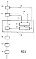
- This normalization circuit 50 comprises, as shown in FIG. 1, a division 59 of the output of the compression circuit 40, or of the output of the scanning conversion circuit 30, by a parameter K i determined as indicated below.
- This parameter K i is considered to depend on the one hand on the place, in the current block, of the coefficient occurring on the "dividend" input of the division circuit 59, that is to say of the coefficient obtained once the scanning conversion performed to have a one-dimensional suite.
- This parameter K i also depends on the average standard N m on the block, that is to say the filling rate of the regulation memory, provided, as indicated below, in the flow regulation circuit. which constitutes the terminal element of the coding device according to the invention.
- any coder which operates on blocks generally introduces two types of distortions.
- the first ones, called the mesh effect, occur in quasi-uniform areas where the intensity variations are extremely gradual. After coding, there are sudden changes in intensity from block to block in these areas, the visual effect of which is very annoying.
- the seconds result from the components of the coding noise which are outside the bandwidth of the contours and which distort these contours, while the noise components situated in the spectral band of the contours are themselves masked by said contours.
- the parameter K i is therefore considered to depend on the activity class of the current block, which will reflect the importance of the average luminance attached to the block considered.
- This coefficient located at the head of the matrix of coefficients of each block, is in fact coded in a particular way (for example, linear quantization then coding by nine bits) to avoid that differences in luminance from block to block others are perceived by the eye. But other criteria for defining the activity could be retained, for example the value of the sum of the coefficients squared.
- the place in the current block is provided by the index i which affects each coefficient and which is supplied to the circuit 50 by a connection 15 coming from the output of the circuit for transformation into discrete cosine 10.
- the average norm on the current block which is a value that is higher the more the regulation memory is full, is supplied to circuit 50 by a connection 85 coming from the output of said regulation memory.
- the activity class in the example described and represented here, is provided by comparison, with thresholds, of the absolute value of the coefficients (with the exception of the first). In the present case, three thresholds and therefore four activity classes have been selected.
- the comparison is carried out in a class 90 determination circuit provided at the output of the discrete cosine transformation circuit 10 and connected to circuit 50 by a connection 95.
- the thresholds introduced into circuit 90 have been previously defined, for example either at using subjective tests, depending on the classification which is considered preferable on a certain number of reference images, ie by imposing an equal distribution of the blocks in the different classes, the lowest activity therefore corresponding to the case where the block considered is practically uniform, or with slightly contrasted contours.
- a memory 51 of the circuit 50 provides a coefficient G i which is sent to a standard calculation circuit 52.
- This circuit 52 weights l 'help of this coefficient G i the mean standard value N m supplied by the connection 85 and finally delivers the parameter K i which is sent to the “divider” input of the division circuit 59.
- This weighting contributes to minimizing the distortions mentioned previously and due to block coding. It indeed makes it possible to vary according to the class the slope of the curve which gives the normalization parameter K i , and therefore the quantization step, as a function of the order of the coefficient. An example of these curves is represented in FIG.
- the normalization circuit 50 is followed by a quantization circuit 60.
- the quantification operation is intended, as we know, to convert the normalized value of each coefficient, expressed with a floating point, into an integer value, either by a simple rounded, preferably by truncation, taking the whole part of the value before quantification. It is obvious that, subject to such a quantification, a certain number of values between 0 and 1 are replaced by the value 0, which decreases the number of significant coefficients to be transmitted and therefore goes in the direction of data compression. wanted. Such a quantization circuit is known and will therefore not be described further. We will simply recall, as we saw above, that the quantification can be linear or on the contrary with variable pitch.
- the output of the quantization circuit 60 is then sent, in a known manner, to a coding circuit 70, comprising here tables of values coded according to a Huffman code, for coding either values of coefficients (variable length coding) or of lengths of ranges (coding by ranges ).
- the output of the coding circuit 70 is finally connected to the input of a flow regulation circuit 80, which therefore receives the values thus coded at a variable rate and restores them on its main output with a constant rate.
- This main output constitutes the output of the coding device according to the invention.
- An auxiliary output of the flow regulation circuit returns to the normalization circuit 50, via the return connection 85, the average standard value N m used to compose the value of the global normalization parameter (the parameter K i ) by which is divided the output of the compression circuit 40 (or of the sweep conversion circuit if this circuit 40 is omitted).
- the invention is not limited by the shape (square or rectangular in particular) or by the dimensions of the blocks which subdivide the image.
- the correlation between neighboring points of an image (or of a frame) decreases when the distance between these points increases, it is wise to operate the cosine transformation, in circuit 10, on blocks of reduced dimensions, for example 8 x 4 blocks like that of FIG. 2d.
- This choice also leads to varying more precisely the normalization parameter as a function of the activity of the blocks.
- this decoding device also relates to the decoding device making it possible to carry out the operations reverse of those which have just been described, on reception of digital video signals having undergone such coding.
- this decoding device comprises at input a rate regulation circuit 100 which receives according to the bit rate of the channel the binary elements sent by the coding device and restores them on its main output with a variable flow.
- This main output is connected to a decoding circuit 110 which, in the absence of errors on the channel, faithfully reconstructs the information which was present on transmission at the input of the coding circuit.
- An auxiliary output 115 of the circuit 100 delivers as a function of its degree of filling the mean standard value Nm used to recompose the value of the global normalization parameter Ki.
- this parameter is calculated not only as a function of Nm, but also in function of the position of the coefficient and of the class to which the block belongs.
- the class is transmitted online and is delivered on an auxiliary output 125 of the decoding circuit 110.
- the place in the current block is provided on another auxiliary output 135 of this same decoding circuit 110.
- a memory 121 of the normalization circuit 120 provides a coefficient Gi which is sent to a standard calculation circuit 122.
- This circuit uses the coefficient to weight the standard value average Nm supplied by the connection 115, and finally delivers the parameter Ki which is sent no longer on a divider circuit but on a multiplication circuit 129.
- the output of the normalization circuit 120 is then possibly decompressed in a circuit 130. This decompression is symmetrical with the compression operation carried out at the level of the circuit 40 and only takes place if the circuit 40 was itself present in the device. coding, that is to say when the quantization performed was non-linear.
- the values obtained are then supplied to a scanning conversion circuit 140 intended to convert the one-dimensional sequence of values into a two-dimensional sequence F ' i (u, v), then a reverse transformation circuit 150 allows blocks of points d to be reconstructed. image, said transformation being the reverse of that carried out in the coding device by the correlation reduction circuit.
Claims (5)
- Vorrichtung zum Codieren von digitalen Videosignalen mit einer Korrelationsreduktionsschaltung (10), welche die besagten digitalen Signale erhält, welche typisch sind für die Bildleuchtdichte oder die Farbsättigung einer bestimmten Anzahl von Punkten eines in Blöcke aufgeteilten Bildes, einer Abtastumwandlungsschaltung (30), welche die zweidimensionale Folge der Ausgangskoeffizientenwerte Fi (u,v) der Korrelationsreduktionsschaltung (10) in eine monodimensionale Folge umwandelt, einer Normalisierungsschaltung (50), einer Quantisierungsschaltung (60), die jeden normalisierten Ausgangswert von der Normalisierungsschaltung in einen vollen Wert umwandelt, einer Codierschaltung (70) der besagten quantisierten Werte und einer Übertragungsgeschwindigkeitsregelungsschaltung (80) welche entsprechend einer veränderlichen Übertragungsgeschwindigkeit die genannten codierten Werte erhält, und einerseits einen mit der Übertragungsgeschwindigkeit verknüpften mittleren Normwert Nm an die Normalisierungsschaltung (50) zurückgibt und andererseits mit einer konstanten Übertragungsgeschwindigkeit codierte Werte an den Ausgang der Codiervorrichtung liefert, dadurch gekennzeichnet, daß die besagte Normalisierungsschaltung folgendes enthält:(a) einen Speicher (51) zum Speichern von Gewichtungskoeffizienten, der einerseits durch den Lagenindex i jedes Wertes Fi (u,v) des Blockes, der sich gerade auf einer ersten Eingangsverbindung (15) der Normalisierungsschaltung (50) befindet und von der Korrelationsreduktionsschaltung (10) geliefert wird, und andererseits durch einen typischen Wert der Wirksamkeit des bestehenden Blocks adressiert ist, der sich auf einer zweiten Eingangsverbindung (95) befindet und ebenfalls von dieser Korrelationsreduktionsschaltung geliefert wird, jedoch über eine Klassenbestimmungsschaltung (90), die seriell zwischen der besagten Korrelationsreduktionsschaltung und dem besagten Speicher vorgesehen ist;(b) eine Normberechnungsschaltung (52) zum Berechnen der Norm Ki aus einerseits dem besagten, von der Übertragungsgeschwindigkeitsregelungsschaltung (80) gelieferten mittleren Normwert und andererseits dem Gewichtungskoeffizienten, der von dem besagten Speicher (51) der Normalisierungsschaltung geliefert wird;(c) eine Teilungsschaltung (59) zum Teilen des Ausgangs der Abtastumwandlungsschaltung (30) durch den Koeffizienten Ki entsprechend dem Ausgang der genannten Normberechnungsschaltung (52).
- Vorrichtung nach dem Anspruch 1, dadurch gekennzeichnet, daß die Klassenbestimmungsschaltung (90) Vergleichsmittel zum Vergleichen eines typischen Wertes des laufenden Blocks mit (n-1) verschiedenen Schwellen und Auswahlmittel zum Wählen zwischen n verschiedenen Klassenwerten, je nach Ergebnis der besagten (n-1) Vergleiche, enthält.
- Vorrichtung nach dem Anspruch 2, dadurch gekennzeichnet, daß der besagte typische Wert des laufenden Blocks der Absolutwert des größten Koeffizienten Fi (u,v) dieses laufenden Blocks ist, wobei der erste Koeffizient F (0,0) des besagten Blocks von dieser Auswahl eines typischen Wertes des Blocks ausgeschlossen ist.
- Vorrichtung nach dem Anspruch 2, dadurch gekennzeichnet, daß der besagte typische Wert des laufenden Blocks den Wert der Summe der Koeffizienten Fi (u,v) im Quadrat darstellt, wobei der erste Koeffizient F (0,0) des besagten Blocks von dieser Auswahl eines typischen Wertes des Blocks ausgeschlossen ist.
- Vorrichtung zum Decodieren von digitalen Videosignalen, die bereits in einer Codiervorrichtung nach einem der Ansprüche 1 bis 4 einer Codierung unterzogen wurden, wobei die besagte Decodiervorrichtung in Reihe eine zweite Übertragungsgeschwindigkeitsregelungsschaltung (100), eine Decodierschaltung (110), eine reziproke Normalisierungsschaltung (120), eine reziproke Abtastkonversionsschaltung (140) und eine Umwandlungsschaltung (150) enthält, wobei die Umwandlung reziprok ist zu der durch die besagte Korrelationsreduktionsschaltung bewirkten Umwandlung, dadurch gekennzeichnet, daß die Normalisierungsschaltung (120) selbst folgende Elemente enthält:(a) einen zweiten Speicher (121) zum Speichern von Gewichtungskoeffizienten, der einerseits durch den Lagenindex i des laufenden Blocks, der sich auf einer ersten Eingangsverbindung (125) der reziproken Normalisierungsschaltung (120) befindet und von der Decodierschaltung (110) geliefert wird, und andererseits durch einen Wert, repräsentativ für die Wirkung des laufenden Blocks, der sich an einer zweiten Eingangsverbindung (135) befindet und ebenfalls von der Decodierschaltung (110) geliefert wird, adressiert ist;(b) eine zweite Normberechnungsschaltung (122) zum Berechnen der Norm Ki, aus einerseits dem von der Übertragungsgeschwindigkeitsregelungsschaltung (100) gelieferten mittleren Normwert Nm und andererseits dem Gewichtungskoeffizienten, der von dem besagten zweiten Speicher (121) geliefert wird;(c) eine Multiplikationsschaltung (129) zum Multiplizieren des Ausgangs der Decodierschaltung (110) mit dem entsprechenden Ausgangskoeffizienten Ki der besagten zweiten Normberechnungsschaltung (122).
Applications Claiming Priority (2)
| Application Number | Priority Date | Filing Date | Title |
|---|---|---|---|
| FR8713429A FR2621194B1 (fr) | 1987-09-29 | 1987-09-29 | Dispositif de codage de signaux video numeriques |
| FR8713429 | 1987-09-29 |
Publications (2)
| Publication Number | Publication Date |
|---|---|
| EP0310175A1 EP0310175A1 (de) | 1989-04-05 |
| EP0310175B1 true EP0310175B1 (de) | 1994-07-13 |
Family
ID=9355319
Family Applications (1)
| Application Number | Title | Priority Date | Filing Date |
|---|---|---|---|
| EP88202049A Expired - Lifetime EP0310175B1 (de) | 1987-09-29 | 1988-09-20 | Vorrichtung zum Codieren von digitalen Videosignalen und eine entsprechende Decodiervorrichtung |
Country Status (7)
| Country | Link |
|---|---|
| US (1) | US4920414A (de) |
| EP (1) | EP0310175B1 (de) |
| JP (1) | JP2661985B2 (de) |
| KR (1) | KR890006089A (de) |
| AT (1) | ATE108595T1 (de) |
| DE (1) | DE3850627T2 (de) |
| FR (1) | FR2621194B1 (de) |
Families Citing this family (35)
| Publication number | Priority date | Publication date | Assignee | Title |
|---|---|---|---|---|
| US5371811A (en) * | 1987-07-09 | 1994-12-06 | British Telecommunications Public Limited Company | Data encoding |
| US6563875B2 (en) * | 1987-12-30 | 2003-05-13 | Thomson Licensing S.A. | Adaptive method of encoding and decoding a series of pictures by transformation, and devices for implementing this method |
| US5170264A (en) * | 1988-12-10 | 1992-12-08 | Fuji Photo Film Co., Ltd. | Compression coding device and expansion decoding device for a picture signal |
| US5051840A (en) * | 1988-12-14 | 1991-09-24 | Fuji Photo Film Co., Ltd. | Device for coding a picture signal by compression |
| FR2644962A1 (fr) * | 1989-03-24 | 1990-09-28 | Labo Electronique Physique | Dispositif de codage de signaux video numeriques |
| US5179442A (en) * | 1989-06-02 | 1993-01-12 | North American Philips Corporation | Method and apparatus for digitally processing a high definition television augmentation signal |
| US5128758A (en) * | 1989-06-02 | 1992-07-07 | North American Philips Corporation | Method and apparatus for digitally processing a high definition television augmentation signal |
| NL8901661A (nl) * | 1989-06-30 | 1991-01-16 | Philips Nv | Televisiesysteem voor digitale overdracht van beeldsignalen. |
| FR2652213A1 (en) * | 1989-09-15 | 1991-03-22 | Philips Electronique Lab | Device for decoding signals previously transmitted and/or stored after data rate reduction |
| JPH03129987A (ja) * | 1989-10-14 | 1991-06-03 | Sony Corp | 映像信号符号化装置及び映像信号符号化方法 |
| FR2653953A1 (fr) * | 1989-10-27 | 1991-05-03 | Philips Electronique Lab | Dispositif de codage comportant un codeur a mots de longueur variable et dispositif de decodage associe. |
| US4974078A (en) * | 1989-11-13 | 1990-11-27 | Eastman Kodak Company | Digital compression method and system with improved coding efficiency |
| DE69033946T2 (de) * | 1989-12-25 | 2002-11-21 | Mitsubishi Electric Corp | Kodierungsgerät |
| US5542008A (en) * | 1990-02-28 | 1996-07-30 | Victor Company Of Japan, Ltd. | Method of and apparatus for compressing image representing signals |
| US5291282A (en) * | 1990-04-19 | 1994-03-01 | Olympus Optical Co., Ltd. | Image data coding apparatus and method capable of controlling amount of codes |
| GB2252001B (en) * | 1991-01-11 | 1995-01-04 | Sony Broadcast & Communication | Storage of video signals |
| US5742345A (en) * | 1991-07-05 | 1998-04-21 | Samsung Electronics Co., Ltd. | System for transmitting and receiving video signals using interpolation of adaptive factor |
| US5454051A (en) * | 1991-08-05 | 1995-09-26 | Eastman Kodak Company | Method of reducing block artifacts created by block transform compression algorithms |
| US5355450A (en) * | 1992-04-10 | 1994-10-11 | Avid Technology, Inc. | Media composer with adjustable source material compression |
| US5253055A (en) * | 1992-07-02 | 1993-10-12 | At&T Bell Laboratories | Efficient frequency scalable video encoding with coefficient selection |
| JPH06274612A (ja) * | 1993-03-17 | 1994-09-30 | Matsushita Electric Ind Co Ltd | 画像処理装置 |
| EP0660619A1 (de) * | 1993-12-22 | 1995-06-28 | Laboratoires D'electronique Philips S.A.S. | Verfahren zur variablen Längenkodierung von Bildern und Vorrichtung zur Ausführung eines solchen Verfahrens |
| US5719961A (en) * | 1994-07-22 | 1998-02-17 | Apple Computer, Inc. | Adaptive technique for encoder and decoder signal transformation |
| US6094453A (en) * | 1996-10-11 | 2000-07-25 | Digital Accelerator Corporation | Digital data compression with quad-tree coding of header file |
| US7269219B1 (en) | 1997-02-14 | 2007-09-11 | At&T Corp. | Non-linear quantizer for video coding |
| EP1359766A3 (de) * | 1997-02-14 | 2005-02-16 | AT&T Corp. | Verfahren zur Erzeugung eines dequantizierten DC-Luminanz oder DC-Chrominanz Koeffizienten |
| US6347116B1 (en) | 1997-02-14 | 2002-02-12 | At&T Corp. | Non-linear quantizer for video coding |
| JP3791003B2 (ja) * | 2001-05-21 | 2006-06-28 | ソニー株式会社 | 画像処理装置および方法、記録媒体、並びにプログラム |
| US7889792B2 (en) * | 2003-12-24 | 2011-02-15 | Apple Inc. | Method and system for video encoding using a variable number of B frames |
| US7492820B2 (en) * | 2004-02-06 | 2009-02-17 | Apple Inc. | Rate control for video coder employing adaptive linear regression bits modeling |
| US7869503B2 (en) | 2004-02-06 | 2011-01-11 | Apple Inc. | Rate and quality controller for H.264/AVC video coder and scene analyzer therefor |
| US7453938B2 (en) * | 2004-02-06 | 2008-11-18 | Apple Inc. | Target bitrate estimator, picture activity and buffer management in rate control for video coder |
| US7986731B2 (en) * | 2004-02-06 | 2011-07-26 | Apple Inc. | H.264/AVC coder incorporating rate and quality controller |
| US20050286629A1 (en) * | 2004-06-25 | 2005-12-29 | Adriana Dumitras | Coding of scene cuts in video sequences using non-reference frames |
| JP2015002462A (ja) * | 2013-06-17 | 2015-01-05 | ソニー株式会社 | 画像圧縮回路、画像圧縮方法、および伝送システム |
Family Cites Families (8)
| Publication number | Priority date | Publication date | Assignee | Title |
|---|---|---|---|---|
| US4394774A (en) * | 1978-12-15 | 1983-07-19 | Compression Labs, Inc. | Digital video compression system and methods utilizing scene adaptive coding with rate buffer feedback |
| US4541012A (en) * | 1982-01-04 | 1985-09-10 | Compression Labs, Inc. | Video bandwidth reduction system employing interframe block differencing and transform domain coding |
| AU570439B2 (en) * | 1983-03-28 | 1988-03-17 | Compression Labs, Inc. | A combined intraframe and interframe transform coding system |
| DE3414982A1 (de) * | 1984-04-19 | 1985-10-31 | Siemens AG, 1000 Berlin und 8000 München | Verfahren zur digitalen uebertragung von bildsignalen |
| FR2575351B1 (fr) * | 1984-12-21 | 1988-05-13 | Thomson Csf | Procede adaptatif de codage et de decodage d'une suite d'images par transformation, et dispositifs pour la mise en oeuvre de ce procede |
| JPS62230281A (ja) * | 1986-03-31 | 1987-10-08 | Toshiba Corp | 画像伝送方式 |
| US4774587A (en) * | 1987-06-02 | 1988-09-27 | Eastman Kodak Company | Still video transceiver processor |
| US4780761A (en) * | 1987-06-02 | 1988-10-25 | Eastman Kodak Company | Digital image compression and transmission system visually weighted transform coefficients |
-
1987
- 1987-09-29 FR FR8713429A patent/FR2621194B1/fr not_active Expired
-
1988
- 1988-09-20 AT AT88202049T patent/ATE108595T1/de not_active IP Right Cessation
- 1988-09-20 EP EP88202049A patent/EP0310175B1/de not_active Expired - Lifetime
- 1988-09-20 DE DE3850627T patent/DE3850627T2/de not_active Expired - Fee Related
- 1988-09-26 JP JP63239089A patent/JP2661985B2/ja not_active Expired - Lifetime
- 1988-09-27 US US07/250,019 patent/US4920414A/en not_active Expired - Fee Related
- 1988-09-28 KR KR1019880012519A patent/KR890006089A/ko active IP Right Grant
Non-Patent Citations (1)
| Title |
|---|
| 1985 IEEE MILITARY COMMUNICATIONS CONFERENCE, MIlCOM '85, 20-23 octobre 1985, Boston, MA., US, "The electronic battle: A new era in military communications", Conference record vol. 2 des 3, pages 628, 634, IEEE Communications Society; H. MAGA1 et al.: "Image coding system - A single processor implementation" * |
Also Published As
| Publication number | Publication date |
|---|---|
| FR2621194A1 (fr) | 1989-03-31 |
| KR890006089A (ko) | 1989-05-18 |
| JPH01165283A (ja) | 1989-06-29 |
| ATE108595T1 (de) | 1994-07-15 |
| FR2621194B1 (fr) | 1989-12-29 |
| US4920414A (en) | 1990-04-24 |
| DE3850627T2 (de) | 1995-02-23 |
| DE3850627D1 (de) | 1994-08-18 |
| EP0310175A1 (de) | 1989-04-05 |
| JP2661985B2 (ja) | 1997-10-08 |
Similar Documents
| Publication | Publication Date | Title |
|---|---|---|
| EP0310175B1 (de) | Vorrichtung zum Codieren von digitalen Videosignalen und eine entsprechende Decodiervorrichtung | |
| EP0294357B1 (de) | Kodierungsverfahren von Bildsignalen | |
| EP0189703B1 (de) | Verfahren zur adaptiven Transformationskodierung und Dekodierung einer Bildfolge und Geräte zur Durchführung dieses Verfahrens | |
| EP0246701B1 (de) | DPCM-Kodierer und zugehöriger Dekodierer | |
| EP0012632A1 (de) | Kompression und Expansion (Quantizierung) von digitalen differenzcodierten Fernsehsignalen | |
| EP2183851A1 (de) | Codierung/decodierung durch symbolpläne mit dynamischer berechnung von wahrscheinlichkeitstabellen | |
| EP0448491A1 (de) | Verfahren zur Kodierung und Übertragung von digitalen Bildern einer Bildsequenz mit mindestens zwei Qualitätsniveaus und zugehörige GerÀ¤te | |
| FR2754127A1 (fr) | Procede de codage/decodage de signal video sur la base d'une quantification de treillis adaptative | |
| FR2627926A1 (fr) | Procede et dispositif de codage de signaux video numeriques, et dispositif de decodage correspondant | |
| EP0389050A1 (de) | Vorrichtung zum Kodieren von digitalen Videosignalen | |
| EP0668004B1 (de) | Verfahren und Vorrichtung zur Ratenreduktion für Bildaufzeichnung | |
| FR2763766A1 (fr) | Procede et dispositif de mise en oeuvre d'un systeme a ondelette noye reversible | |
| EP0490799A1 (de) | Bildkodierungsvorrichtung und -verfahren und zugehöriges Sendesystem und Empfänger | |
| EP0322058B1 (de) | Anordnung zur Regelung der Übertragungsgeschwindigkeit für mindestens zwei Komponenten eines digitalen Videosignals | |
| FR2849982A1 (fr) | Decodage d'une image numerique codee selon plusieurs niveaux de resolution | |
| EP0053064B1 (de) | Digitales Übertragungssystem mit adaptiver Codierung abgetasteter und orthogonal transformierter, analoger Informationen | |
| EP2005756A2 (de) | Eingeschränkte vektorquantisierung | |
| FR2684829A1 (fr) | Methodes de synthese de signaux de texture et de transmission et/ou stockage de tels signaux, ainsi que dispositifs et systemes pour leur mise en óoeuvre. | |
| FR2613559A1 (fr) | Appareil de modulation par impulsions codees differentielle et son procede de fonctionnement | |
| EP0063990B1 (de) | Verfahren zur Bildübertragung mit beschränktem Datafluss; Übertragungssystem zur Durchführung dieses Verfahrens | |
| EP3529987A1 (de) | Methode für die kodierung und dekodierung von bildparametern, vorrichtung für die kodierung und dekodierung von bildparametern und zugehörige computerprogramme | |
| FR2597282A1 (fr) | Procede de quantification dans un codage par transformation pour la transmission de signaux d'image | |
| FR2654285A1 (fr) | Systeme de compression d'images numeriques appartenant a une sequence d'images, a quantification adaptative en fonction d'une information psychovisuelle. | |
| WO1993002526A1 (fr) | Procede de compression de sequences d'images numeriques | |
| FR2717927A1 (fr) | Procédé et appareil de compression, de palettisation, d'émission et de réception d'images en couleur. |
Legal Events
| Date | Code | Title | Description |
|---|---|---|---|
| PUAI | Public reference made under article 153(3) epc to a published international application that has entered the european phase |
Free format text: ORIGINAL CODE: 0009012 |
|
| AK | Designated contracting states |
Kind code of ref document: A1 Designated state(s): AT DE FR GB IT SE |
|
| 17P | Request for examination filed |
Effective date: 19890928 |
|
| RAP1 | Party data changed (applicant data changed or rights of an application transferred) |
Owner name: N.V. PHILIPS' GLOEILAMPENFABRIEKEN Owner name: LABORATOIRES D'ELECTRONIQUE PHILIPS |
|
| 17Q | First examination report despatched |
Effective date: 19920702 |
|
| GRAA | (expected) grant |
Free format text: ORIGINAL CODE: 0009210 |
|
| AK | Designated contracting states |
Kind code of ref document: B1 Designated state(s): AT DE FR GB IT SE |
|
| PG25 | Lapsed in a contracting state [announced via postgrant information from national office to epo] |
Ref country code: AT Effective date: 19940713 |
|
| REF | Corresponds to: |
Ref document number: 108595 Country of ref document: AT Date of ref document: 19940715 Kind code of ref document: T |
|
| REF | Corresponds to: |
Ref document number: 3850627 Country of ref document: DE Date of ref document: 19940818 |
|
| ITF | It: translation for a ep patent filed |
Owner name: ING. C. GREGORJ S.P.A. |
|
| PG25 | Lapsed in a contracting state [announced via postgrant information from national office to epo] |
Ref country code: SE Effective date: 19941013 |
|
| GBT | Gb: translation of ep patent filed (gb section 77(6)(a)/1977) |
Effective date: 19941005 |
|
| ITPR | It: changes in ownership of a european patent |
Owner name: CAMBIO RAGIONE SOCIALE;PHILIPS ELECTRONICS N.V. |
|
| PLBE | No opposition filed within time limit |
Free format text: ORIGINAL CODE: 0009261 |
|
| STAA | Information on the status of an ep patent application or granted ep patent |
Free format text: STATUS: NO OPPOSITION FILED WITHIN TIME LIMIT |
|
| 26N | No opposition filed | ||
| REG | Reference to a national code |
Ref country code: FR Ref legal event code: CJ Ref country code: FR Ref legal event code: CD |
|
| REG | Reference to a national code |
Ref country code: FR Ref legal event code: TP |
|
| PGFP | Annual fee paid to national office [announced via postgrant information from national office to epo] |
Ref country code: FR Payment date: 20000925 Year of fee payment: 13 |
|
| PGFP | Annual fee paid to national office [announced via postgrant information from national office to epo] |
Ref country code: GB Payment date: 20000929 Year of fee payment: 13 |
|
| PGFP | Annual fee paid to national office [announced via postgrant information from national office to epo] |
Ref country code: DE Payment date: 20001122 Year of fee payment: 13 |
|
| PG25 | Lapsed in a contracting state [announced via postgrant information from national office to epo] |
Ref country code: GB Free format text: LAPSE BECAUSE OF NON-PAYMENT OF DUE FEES Effective date: 20010920 |
|
| REG | Reference to a national code |
Ref country code: GB Ref legal event code: IF02 |
|
| PG25 | Lapsed in a contracting state [announced via postgrant information from national office to epo] |
Ref country code: DE Free format text: LAPSE BECAUSE OF NON-PAYMENT OF DUE FEES Effective date: 20020501 |
|
| GBPC | Gb: european patent ceased through non-payment of renewal fee |
Effective date: 20010920 |
|
| PG25 | Lapsed in a contracting state [announced via postgrant information from national office to epo] |
Ref country code: FR Free format text: LAPSE BECAUSE OF NON-PAYMENT OF DUE FEES Effective date: 20020531 |
|
| REG | Reference to a national code |
Ref country code: FR Ref legal event code: ST |
|
| PG25 | Lapsed in a contracting state [announced via postgrant information from national office to epo] |
Ref country code: IT Free format text: LAPSE BECAUSE OF NON-PAYMENT OF DUE FEES;WARNING: LAPSES OF ITALIAN PATENTS WITH EFFECTIVE DATE BEFORE 2007 MAY HAVE OCCURRED AT ANY TIME BEFORE 2007. THE CORRECT EFFECTIVE DATE MAY BE DIFFERENT FROM THE ONE RECORDED. Effective date: 20050920 |