EP0310175B1 - Coding device for digital video signals, and decoding device therefor - Google Patents
Coding device for digital video signals, and decoding device therefor Download PDFInfo
- Publication number
- EP0310175B1 EP0310175B1 EP88202049A EP88202049A EP0310175B1 EP 0310175 B1 EP0310175 B1 EP 0310175B1 EP 88202049 A EP88202049 A EP 88202049A EP 88202049 A EP88202049 A EP 88202049A EP 0310175 B1 EP0310175 B1 EP 0310175B1
- Authority
- EP
- European Patent Office
- Prior art keywords
- circuit
- value
- hand
- normalization
- block
- Prior art date
- Legal status (The legal status is an assumption and is not a legal conclusion. Google has not performed a legal analysis and makes no representation as to the accuracy of the status listed.)
- Expired - Lifetime
Links
Images


Classifications
-
- H—ELECTRICITY
- H04—ELECTRIC COMMUNICATION TECHNIQUE
- H04N—PICTORIAL COMMUNICATION, e.g. TELEVISION
- H04N11/00—Colour television systems
- H04N11/04—Colour television systems using pulse code modulation
-
- H—ELECTRICITY
- H04—ELECTRIC COMMUNICATION TECHNIQUE
- H04N—PICTORIAL COMMUNICATION, e.g. TELEVISION
- H04N19/00—Methods or arrangements for coding, decoding, compressing or decompressing digital video signals
- H04N19/10—Methods or arrangements for coding, decoding, compressing or decompressing digital video signals using adaptive coding
- H04N19/169—Methods or arrangements for coding, decoding, compressing or decompressing digital video signals using adaptive coding characterised by the coding unit, i.e. the structural portion or semantic portion of the video signal being the object or the subject of the adaptive coding
- H04N19/18—Methods or arrangements for coding, decoding, compressing or decompressing digital video signals using adaptive coding characterised by the coding unit, i.e. the structural portion or semantic portion of the video signal being the object or the subject of the adaptive coding the unit being a set of transform coefficients
-
- H—ELECTRICITY
- H04—ELECTRIC COMMUNICATION TECHNIQUE
- H04N—PICTORIAL COMMUNICATION, e.g. TELEVISION
- H04N19/00—Methods or arrangements for coding, decoding, compressing or decompressing digital video signals
- H04N19/10—Methods or arrangements for coding, decoding, compressing or decompressing digital video signals using adaptive coding
- H04N19/102—Methods or arrangements for coding, decoding, compressing or decompressing digital video signals using adaptive coding characterised by the element, parameter or selection affected or controlled by the adaptive coding
- H04N19/124—Quantisation
- H04N19/126—Details of normalisation or weighting functions, e.g. normalisation matrices or variable uniform quantisers
-
- H—ELECTRICITY
- H04—ELECTRIC COMMUNICATION TECHNIQUE
- H04N—PICTORIAL COMMUNICATION, e.g. TELEVISION
- H04N19/00—Methods or arrangements for coding, decoding, compressing or decompressing digital video signals
- H04N19/10—Methods or arrangements for coding, decoding, compressing or decompressing digital video signals using adaptive coding
- H04N19/102—Methods or arrangements for coding, decoding, compressing or decompressing digital video signals using adaptive coding characterised by the element, parameter or selection affected or controlled by the adaptive coding
- H04N19/129—Scanning of coding units, e.g. zig-zag scan of transform coefficients or flexible macroblock ordering [FMO]
-
- H—ELECTRICITY
- H04—ELECTRIC COMMUNICATION TECHNIQUE
- H04N—PICTORIAL COMMUNICATION, e.g. TELEVISION
- H04N19/00—Methods or arrangements for coding, decoding, compressing or decompressing digital video signals
- H04N19/10—Methods or arrangements for coding, decoding, compressing or decompressing digital video signals using adaptive coding
- H04N19/134—Methods or arrangements for coding, decoding, compressing or decompressing digital video signals using adaptive coding characterised by the element, parameter or criterion affecting or controlling the adaptive coding
- H04N19/136—Incoming video signal characteristics or properties
- H04N19/14—Coding unit complexity, e.g. amount of activity or edge presence estimation
-
- H—ELECTRICITY
- H04—ELECTRIC COMMUNICATION TECHNIQUE
- H04N—PICTORIAL COMMUNICATION, e.g. TELEVISION
- H04N19/00—Methods or arrangements for coding, decoding, compressing or decompressing digital video signals
- H04N19/10—Methods or arrangements for coding, decoding, compressing or decompressing digital video signals using adaptive coding
- H04N19/169—Methods or arrangements for coding, decoding, compressing or decompressing digital video signals using adaptive coding characterised by the coding unit, i.e. the structural portion or semantic portion of the video signal being the object or the subject of the adaptive coding
- H04N19/17—Methods or arrangements for coding, decoding, compressing or decompressing digital video signals using adaptive coding characterised by the coding unit, i.e. the structural portion or semantic portion of the video signal being the object or the subject of the adaptive coding the unit being an image region, e.g. an object
- H04N19/176—Methods or arrangements for coding, decoding, compressing or decompressing digital video signals using adaptive coding characterised by the coding unit, i.e. the structural portion or semantic portion of the video signal being the object or the subject of the adaptive coding the unit being an image region, e.g. an object the region being a block, e.g. a macroblock
-
- H—ELECTRICITY
- H04—ELECTRIC COMMUNICATION TECHNIQUE
- H04N—PICTORIAL COMMUNICATION, e.g. TELEVISION
- H04N19/00—Methods or arrangements for coding, decoding, compressing or decompressing digital video signals
- H04N19/42—Methods or arrangements for coding, decoding, compressing or decompressing digital video signals characterised by implementation details or hardware specially adapted for video compression or decompression, e.g. dedicated software implementation
- H04N19/423—Methods or arrangements for coding, decoding, compressing or decompressing digital video signals characterised by implementation details or hardware specially adapted for video compression or decompression, e.g. dedicated software implementation characterised by memory arrangements
-
- H—ELECTRICITY
- H04—ELECTRIC COMMUNICATION TECHNIQUE
- H04N—PICTORIAL COMMUNICATION, e.g. TELEVISION
- H04N19/00—Methods or arrangements for coding, decoding, compressing or decompressing digital video signals
- H04N19/60—Methods or arrangements for coding, decoding, compressing or decompressing digital video signals using transform coding
-
- H—ELECTRICITY
- H04—ELECTRIC COMMUNICATION TECHNIQUE
- H04N—PICTORIAL COMMUNICATION, e.g. TELEVISION
- H04N19/00—Methods or arrangements for coding, decoding, compressing or decompressing digital video signals
- H04N19/10—Methods or arrangements for coding, decoding, compressing or decompressing digital video signals using adaptive coding
- H04N19/102—Methods or arrangements for coding, decoding, compressing or decompressing digital video signals using adaptive coding characterised by the element, parameter or selection affected or controlled by the adaptive coding
- H04N19/124—Quantisation
-
- H—ELECTRICITY
- H04—ELECTRIC COMMUNICATION TECHNIQUE
- H04N—PICTORIAL COMMUNICATION, e.g. TELEVISION
- H04N19/00—Methods or arrangements for coding, decoding, compressing or decompressing digital video signals
- H04N19/10—Methods or arrangements for coding, decoding, compressing or decompressing digital video signals using adaptive coding
- H04N19/134—Methods or arrangements for coding, decoding, compressing or decompressing digital video signals using adaptive coding characterised by the element, parameter or criterion affecting or controlling the adaptive coding
- H04N19/146—Data rate or code amount at the encoder output
- H04N19/152—Data rate or code amount at the encoder output by measuring the fullness of the transmission buffer
Definitions
- the present invention relates to a device for coding digital video signals comprising a correlation reduction circuit, which receives said digital signals representative of the luminance or chrominance of a certain number of points of an image divided into blocks, a circuit conversion converter, which transforms the two-dimensional sequence of values of the coefficients F i (u, v) of output from the correlation reduction circuit into a one-dimensional sequence, a normalization circuit, a quantization circuit, which converts each normalized value of output of the normalization circuit into an integer value, a coding circuit of said quantized values, a flow regulation circuit, which receives said coded values at a variable flow rate and, on the one hand, returns an average standard value linked to said flow to the normalization circuit, on the other hand, delivers on the output of the coding device values coded with a constant flow.
- the invention also relates to a decoding device corresponding to such a coding device.
- the digitization of television signals is an extremely useful solution in the case of links where the disturbing noise is particularly high, satellite links in particular.
- a television picture contains a very large amount of information, the digital representation of which results in a high bit rate.
- the direct digitization of the luminance and chrominance components at frequencies of 13.5 and 6.75 megahertz respectively, imposed by the standards would indeed lead to a bit rate of 216 Meb / s. This speed is completely prohibitive, especially in the case of consumer magnetic recording devices.
- the use of flow reduction techniques is therefore necessary, and all the more feasible when a relatively large redundancy exists in the image.
- United States patent US-A-4,394,774 describes an example of a data compression device which performs coding of video signals by orthogonal transformation.
- This coding is obtained by cutting each image into blocks of determined size, then by applying said orthogonal transformation to each block. The coefficients resulting from this transformation are then divided by a normalization factor, then quantified and coded.
- a normalization factor a normalization factor
- Such a device does not take into account the specific characteristics of each block, in particular the activity of these blocks.
- the influence of the coding used is such, for example, that it introduces very different amplitude defects on the contours depending on the position of the contours in the block.
- the object of the invention is to propose a device for coding video signals which overcomes this type of drawback.
- the proposed structure does indeed remedy the imperfections and distortions caused by coding, and this by providing for classification on each transformed block, according to a classification criterion taking into account the nature of the content of the block to be coded.
- This criterion can for example be the comparison between the maximum of the absolute value of the coefficients of the block (excluding the DC component) and a certain number of thresholds. Satisfactory tests have been obtained in particular with four classes and three thresholds of values fixed at 10, 25 and 50 for a dynamic of the digital samples between 0 and 256.
- Such a classification greatly reduces the visibility of the defects observed (visibility of the structures of the blocks in the quasi-uniform zones and significant noise level along the contours).
- the visibility of the block structure can be further reduced in uniform areas: we can reduce the quantization step on blocks of this type (almost uniform) and on the contrary increase it on those containing coefficients of high amplitude , or modify the quantization step as a function of the position of the coefficient, reducing it for the blocks of little activity to restore the low frequency coefficients well whereas, for the more contrasted blocks, good restitution implies a fairly fine quantification high spatial frequencies.
- the invention thus proposed, by differentiating the treatments according to the nature of the content of the blocks to coding makes it possible to take into account not only objective measures of activity, but also the correlations established between these objective criteria and psychovisual criteria.
- the device firstly comprises a circuit for transformation into a discrete cosine 10.
- This circuit 10 receives a series of digital signals representing in the form of a matrix of values the luminance or chrominance of a certain number of points or elements of an image divided into blocks, and delivers for each block a two-dimensional series of coefficients F i (u, v).
- Figure 2a shows a such image, divided into M x N blocks.
- the transformation into discrete cosine is a known operation, and the expression of these transformation coefficients obtained successively for each block will therefore not be given here. It will simply be recalled that numerous statistical measurements have made it possible to show the very strong correlation between neighboring points of a frame or of an image, and that the object of the transformation is to obtain a set of coefficients more independent than the values. available before transformation.
- the values F i (u, v) are then supplied, via a delay circuit 20, to a scanning conversion circuit 30 intended to convert the two-dimensional series of values F i (u, v) into a one-dimensional suite.
- this monodimensional sequence can for example be a zig-zag sequence like that indicated in FIG. 2c which shows, in a representation of the two-dimensional matrix of the image block transformation coefficients, a type of scan defining the reading order (C1, C2, C3, ... etc ...) and the processing of these coefficients.
- This type of route has the following advantage, namely that it allows, after the quantification operation provided below, to meet long ranges of zero values, which contributes to reducing the amount of information to be transmitted.
- a compression circuit 40 then receives this one-dimensional sequence, called for example X i , to deliver a new one-dimensional sequence X ' i , the sequence of X' i being obtained from X i according to a transformation curve such as that of the Figure 3.
- a quantization operation if this quantization operation is carried out with a variable pitch, the compression circuit 40 can be omitted. If on the contrary the quantization is linear, the presence of the compression circuit makes it possible to reconstitute globally a transformation with variable pitch. This systematic compression is, in either case, justified by the fact that the eye is more sensitive to distortions affecting small amplitude values rather than large ones.
- This normalization circuit 50 comprises, as shown in FIG. 1, a division 59 of the output of the compression circuit 40, or of the output of the scanning conversion circuit 30, by a parameter K i determined as indicated below.
- This parameter K i is considered to depend on the one hand on the place, in the current block, of the coefficient occurring on the "dividend" input of the division circuit 59, that is to say of the coefficient obtained once the scanning conversion performed to have a one-dimensional suite.
- This parameter K i also depends on the average standard N m on the block, that is to say the filling rate of the regulation memory, provided, as indicated below, in the flow regulation circuit. which constitutes the terminal element of the coding device according to the invention.
- any coder which operates on blocks generally introduces two types of distortions.
- the first ones, called the mesh effect, occur in quasi-uniform areas where the intensity variations are extremely gradual. After coding, there are sudden changes in intensity from block to block in these areas, the visual effect of which is very annoying.
- the seconds result from the components of the coding noise which are outside the bandwidth of the contours and which distort these contours, while the noise components situated in the spectral band of the contours are themselves masked by said contours.
- the parameter K i is therefore considered to depend on the activity class of the current block, which will reflect the importance of the average luminance attached to the block considered.
- This coefficient located at the head of the matrix of coefficients of each block, is in fact coded in a particular way (for example, linear quantization then coding by nine bits) to avoid that differences in luminance from block to block others are perceived by the eye. But other criteria for defining the activity could be retained, for example the value of the sum of the coefficients squared.
- the place in the current block is provided by the index i which affects each coefficient and which is supplied to the circuit 50 by a connection 15 coming from the output of the circuit for transformation into discrete cosine 10.
- the average norm on the current block which is a value that is higher the more the regulation memory is full, is supplied to circuit 50 by a connection 85 coming from the output of said regulation memory.
- the activity class in the example described and represented here, is provided by comparison, with thresholds, of the absolute value of the coefficients (with the exception of the first). In the present case, three thresholds and therefore four activity classes have been selected.
- the comparison is carried out in a class 90 determination circuit provided at the output of the discrete cosine transformation circuit 10 and connected to circuit 50 by a connection 95.
- the thresholds introduced into circuit 90 have been previously defined, for example either at using subjective tests, depending on the classification which is considered preferable on a certain number of reference images, ie by imposing an equal distribution of the blocks in the different classes, the lowest activity therefore corresponding to the case where the block considered is practically uniform, or with slightly contrasted contours.
- a memory 51 of the circuit 50 provides a coefficient G i which is sent to a standard calculation circuit 52.
- This circuit 52 weights l 'help of this coefficient G i the mean standard value N m supplied by the connection 85 and finally delivers the parameter K i which is sent to the “divider” input of the division circuit 59.
- This weighting contributes to minimizing the distortions mentioned previously and due to block coding. It indeed makes it possible to vary according to the class the slope of the curve which gives the normalization parameter K i , and therefore the quantization step, as a function of the order of the coefficient. An example of these curves is represented in FIG.
- the normalization circuit 50 is followed by a quantization circuit 60.
- the quantification operation is intended, as we know, to convert the normalized value of each coefficient, expressed with a floating point, into an integer value, either by a simple rounded, preferably by truncation, taking the whole part of the value before quantification. It is obvious that, subject to such a quantification, a certain number of values between 0 and 1 are replaced by the value 0, which decreases the number of significant coefficients to be transmitted and therefore goes in the direction of data compression. wanted. Such a quantization circuit is known and will therefore not be described further. We will simply recall, as we saw above, that the quantification can be linear or on the contrary with variable pitch.
- the output of the quantization circuit 60 is then sent, in a known manner, to a coding circuit 70, comprising here tables of values coded according to a Huffman code, for coding either values of coefficients (variable length coding) or of lengths of ranges (coding by ranges ).
- the output of the coding circuit 70 is finally connected to the input of a flow regulation circuit 80, which therefore receives the values thus coded at a variable rate and restores them on its main output with a constant rate.
- This main output constitutes the output of the coding device according to the invention.
- An auxiliary output of the flow regulation circuit returns to the normalization circuit 50, via the return connection 85, the average standard value N m used to compose the value of the global normalization parameter (the parameter K i ) by which is divided the output of the compression circuit 40 (or of the sweep conversion circuit if this circuit 40 is omitted).
- the invention is not limited by the shape (square or rectangular in particular) or by the dimensions of the blocks which subdivide the image.
- the correlation between neighboring points of an image (or of a frame) decreases when the distance between these points increases, it is wise to operate the cosine transformation, in circuit 10, on blocks of reduced dimensions, for example 8 x 4 blocks like that of FIG. 2d.
- This choice also leads to varying more precisely the normalization parameter as a function of the activity of the blocks.
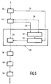
- this decoding device also relates to the decoding device making it possible to carry out the operations reverse of those which have just been described, on reception of digital video signals having undergone such coding.
- this decoding device comprises at input a rate regulation circuit 100 which receives according to the bit rate of the channel the binary elements sent by the coding device and restores them on its main output with a variable flow.
- This main output is connected to a decoding circuit 110 which, in the absence of errors on the channel, faithfully reconstructs the information which was present on transmission at the input of the coding circuit.
- An auxiliary output 115 of the circuit 100 delivers as a function of its degree of filling the mean standard value Nm used to recompose the value of the global normalization parameter Ki.
- this parameter is calculated not only as a function of Nm, but also in function of the position of the coefficient and of the class to which the block belongs.
- the class is transmitted online and is delivered on an auxiliary output 125 of the decoding circuit 110.
- the place in the current block is provided on another auxiliary output 135 of this same decoding circuit 110.
- a memory 121 of the normalization circuit 120 provides a coefficient Gi which is sent to a standard calculation circuit 122.
- This circuit uses the coefficient to weight the standard value average Nm supplied by the connection 115, and finally delivers the parameter Ki which is sent no longer on a divider circuit but on a multiplication circuit 129.
- the output of the normalization circuit 120 is then possibly decompressed in a circuit 130. This decompression is symmetrical with the compression operation carried out at the level of the circuit 40 and only takes place if the circuit 40 was itself present in the device. coding, that is to say when the quantization performed was non-linear.
- the values obtained are then supplied to a scanning conversion circuit 140 intended to convert the one-dimensional sequence of values into a two-dimensional sequence F ' i (u, v), then a reverse transformation circuit 150 allows blocks of points d to be reconstructed. image, said transformation being the reverse of that carried out in the coding device by the correlation reduction circuit.
Abstract
Description
La présente invention concerne un dispositif de codage de signaux vidéo numériques comprenant un circuit de réduction de corrélation, qui reçoit lesdits signaux numériques représentatifs de la luminance ou de la chrominance d'un certain nombre de points d'une image divisée en blocs, un circuit de conversion de balayage, qui transforme la suite bidimensionnelle des valeurs des coefficients Fi(u,v) de sortie du circuit de réduction de corrélation en une suite monodimensionnelle, un circuit de normalisation, un circuit de quantification, qui convertit chaque valeur normalisée de sortie du circuit de normalisation en une valeur entière, un circuit de codage desdites valeurs quantifiées, un circuit de régulation de débit, qui reçoit selon un débit variable lesdites valeurs codées et, d'une part, renvoie une valeur de norme moyenne liée audit débit vers le circuit de normalisation, d'autre part, délivre sur la sortie du dispositif de codage des valeurs codées avec un débit constant. L'invention concerne aussi un dispositif de décodage correspondant à un tel dispositif de codage.The present invention relates to a device for coding digital video signals comprising a correlation reduction circuit, which receives said digital signals representative of the luminance or chrominance of a certain number of points of an image divided into blocks, a circuit conversion converter, which transforms the two-dimensional sequence of values of the coefficients F i (u, v) of output from the correlation reduction circuit into a one-dimensional sequence, a normalization circuit, a quantization circuit, which converts each normalized value of output of the normalization circuit into an integer value, a coding circuit of said quantized values, a flow regulation circuit, which receives said coded values at a variable flow rate and, on the one hand, returns an average standard value linked to said flow to the normalization circuit, on the other hand, delivers on the output of the coding device values coded with a constant flow. The invention also relates to a decoding device corresponding to such a coding device.
La numérisation des signaux de télévision, en vue de leur transmission ou de leur enregistrement, est une solution extrêmement utile dans le cas de liaisons où le bruit perturbateur est particulièrement important, les liaisons par satellite notamment. Une image de télévision contient cependant une très grande quantité d'informations, dont la représentation numérique se traduit par un débit élevé. En échantillonnant les composantes du signal de télévision à une fréquence satisfaisant la condition de Shannon et en opérant une quantification uniforme en 256 niveaux, la numérisation directe des composantes de luminance et de chrominance aux fréquences de 13,5 et de 6,75 mégahertz respectivement, imposées par les normes, conduirait en effet à un débit de 216 Meb/s. Ce débit est tout à fait prohibitif, notamment dans le cas de dispositifs d'enregistrement magnétique grand public. L'emploi de techniques de réduction de débit est donc nécessaire, et d'autant plus réalisable qu'une redondance relativement importante existe dans l'image.The digitization of television signals, with a view to their transmission or recording, is an extremely useful solution in the case of links where the disturbing noise is particularly high, satellite links in particular. A television picture, however, contains a very large amount of information, the digital representation of which results in a high bit rate. By sampling the components of the television signal at a frequency satisfying the Shannon condition and operating a uniform quantization in 256 levels, the direct digitization of the luminance and chrominance components at frequencies of 13.5 and 6.75 megahertz respectively, imposed by the standards, would indeed lead to a bit rate of 216 Meb / s. This speed is completely prohibitive, especially in the case of consumer magnetic recording devices. The use of flow reduction techniques is therefore necessary, and all the more feasible when a relatively large redundancy exists in the image.
Le brevet des Etats-Unis d'Amérique US-A-4 394 774 décrit un exemple de dispositif de compression de données qui réalise un codage des signaux vidéo par transformation orthogonale. Ce codage est obtenu en découpant chaque image en blocs de taille déterminée, puis en appliquant ladite transformation orthogonale à chaque bloc. Les coefficients issus de cette transformation sont alors divisés par un facteur de normalisation, puis quantifiés et codés. Un tel dispositif ne tient cependant pas compte des caractéristiques propres de chaque bloc, en particulier de l'activité de ces blocs. L'influence du codage utilisé est telle, par exemple, que celui-ci introduit sur les contours des défauts d'amplitude très différents selon la position des contours dans le bloc.United States patent US-A-4,394,774 describes an example of a data compression device which performs coding of video signals by orthogonal transformation. This coding is obtained by cutting each image into blocks of determined size, then by applying said orthogonal transformation to each block. The coefficients resulting from this transformation are then divided by a normalization factor, then quantified and coded. However, such a device does not take into account the specific characteristics of each block, in particular the activity of these blocks. The influence of the coding used is such, for example, that it introduces very different amplitude defects on the contours depending on the position of the contours in the block.
Le but de l'invention est de proposer un dispositif de codage de signaux vidéo qui remédie à ce type d'inconvénient.The object of the invention is to propose a device for coding video signals which overcomes this type of drawback.
A cet effet, l'invention concerne un dispositif caractérisé en ce que ledit circuit de normalisation comprend lui-même :
- (a) une mémoire de stockage de coefficients de pondération, adressée d'une part par l'indice i de position de chaque valeur Fi(u,v) du bloc courant, présent sur une première connexion d'entrée du circuit de normalisation et fourni par le circuit de réduction de corrélation, et d'autre part par une valeur représentative de l'activité du bloc courant, présente sur une deuxième connexion d'entrée et également fournie par ce circuit de réduction de corrélation mais par l'intermédiaire d'un circuit de détermination de classe prévu en série entre ledit circuit de réduction de corrélation et ladite mémoire de stockage ;
- (b) un circuit de calcul de norme, à partir d'une part de ladite valeur de norme moyenne fournie par le circuit de régulation de débit et d'autre part du coefficient de pondération fourni par ladite mémoire de stockage du circuit de normalisation ;
- (c) un circuit de division de la sortie du circuit de conversion de balayage par le coefficient Ki correspondant de sortie dudit circuit de calcul de norme.
- (a) a memory for storing weighting coefficients, addressed on the one hand by the position index i of each value F i (u, v) of the current block, present on a first input connection of the normalization circuit and supplied by the correlation reduction circuit, and on the other hand by a value representative of the activity of the current block, present on a second input connection and also supplied by this correlation reduction circuit but via a class determination circuit provided in series between said correlation reduction circuit and said storage memory;
- (b) a standard calculation circuit, on the one hand from said average standard value supplied by the flow control circuit and on the other hand from the weighting coefficient supplied by said storage memory of the normalization circuit;
- (c) a circuit for dividing the output of the scanning conversion circuit by the corresponding coefficient K i of the output of said standard calculation circuit.
La structure proposée remédie en effet aux imperfections et distorsions entraînées par le codage, et ce en prévoyant d'opérer une classification sur chaque bloc transformé, selon un critère de classification prenant en compte la nature du contenu du bloc à coder. Ce critère peut être par exemple la comparaison entre le maximum de la valeur absolue des coefficients du bloc (hors composante continue) et un certain nombre de seuils. Des essais satisfaisants ont été obtenus notamment avec quatre classes et trois seuils de valeurs fixées à 10, 25 et 50 pour une dynamique des échantillons numériques comprise entre 0 et 256.The proposed structure does indeed remedy the imperfections and distortions caused by coding, and this by providing for classification on each transformed block, according to a classification criterion taking into account the nature of the content of the block to be coded. This criterion can for example be the comparison between the maximum of the absolute value of the coefficients of the block (excluding the DC component) and a certain number of thresholds. Satisfactory tests have been obtained in particular with four classes and three thresholds of values fixed at 10, 25 and 50 for a dynamic of the digital samples between 0 and 256.
Une telle classification réduit bien la visibilité des défauts constatés (visibilité des structures des blocs sur les zones quasi-uniformes et niveau de bruit important le long des contours). La visibilité de la structure des blocs peut encore être réduite sur les zones uniformes : on peut réduire le pas de quantification sur les blocs de ce type (à peu près uniformes) et l'augmenter au contraire sur ceux contenant des coefficients d'amplitude élevée, ou modifier le pas de quantification en fonction de la position du coefficient, en le réduisant pour les blocs de peu d'activité pour bien restituer les coefficients basse fréquence alors que, pour les blocs plus contrastés, une bonne restitution implique une quantification assez fine des hautes fréquences spatiales.Such a classification greatly reduces the visibility of the defects observed (visibility of the structures of the blocks in the quasi-uniform zones and significant noise level along the contours). The visibility of the block structure can be further reduced in uniform areas: we can reduce the quantization step on blocks of this type (almost uniform) and on the contrary increase it on those containing coefficients of high amplitude , or modify the quantization step as a function of the position of the coefficient, reducing it for the blocks of little activity to restore the low frequency coefficients well whereas, for the more contrasted blocks, good restitution implies a fairly fine quantification high spatial frequencies.
L'invention ainsi proposée, en différenciant les traitements en fonction de la nature du contenu des blocs à coder, permet de prendre en compte non seulement des mesures objectives d'activité, mais également des corrélations établies entre ces critères objectifs et des critères psychovisuels.The invention thus proposed, by differentiating the treatments according to the nature of the content of the blocks to coding makes it possible to take into account not only objective measures of activity, but also the correlations established between these objective criteria and psychovisual criteria.
Les particularités de l'invention apparaîtront maintenant de façon plus détaillée dans la description qui suit et dans les dessins annexés, donnés à titre d'exemples non limitatifs et dans lesquels :
- la figure 1 montre un exemple de réalisation du dispositif de codage selon l'invention ;
- la figure 2a montre une image divisée en N x M blocs, la figure 2b représente la matrice bidimensionnelle des coefficients de transformation d'un de ces blocs d'image, la figure 2c met en évidence un type de parcours monodimensionnel pour la lecture et le traitement desdits coefficients, la figure 2d montre un autre type de parcours pour un bloc de 32 points d'image, et la figure 2e montre par rapport à la figure 2c une variante de parcours dans laquelle les coefficients sont successivement lus dans différents blocs ;
- la figure 3 est une courbe

- la figure 4 montre un exemple de variation du coefficient de normalisation (et donc du pas de quantification) en fonction de la position des coefficients et pour différentes classes ;
- la figure 5 montre un exemple de réalisation du dispositif de décodage associé au dispositif de codage de la figure 1.
- FIG. 1 shows an exemplary embodiment of the coding device according to the invention;
- FIG. 2a shows an image divided into N × M blocks, FIG. 2b represents the two-dimensional matrix of the transformation coefficients of one of these image blocks, FIG. 2c highlights a type of monodimensional path for reading and processing of said coefficients, FIG. 2d shows another type of journey for a block of 32 image points, and FIG. 2e shows with respect to FIG. 2c a variant of journey in which the coefficients are successively read in different blocks;
- Figure 3 is a curve
- FIG. 4 shows an example of variation of the normalization coefficient (and therefore of the quantization step) as a function of the position of the coefficients and for different classes;
- FIG. 5 shows an exemplary embodiment of the decoding device associated with the coding device of FIG. 1.
Dans l'exemple de réalisation représenté sur la figure 1, le dispositif selon l'invention comprend d'abord un circuit de transformation en cosinus discret 10. Ce circuit 10 reçoit une suite de signaux numériques représentant sous la forme d'une matrice de valeurs la luminance ou la chrominance d'un certain nombre de points ou éléments d'une image divisée en blocs, et délivre pour chaque bloc une suite bidimensionnelle de coefficients Fi(u,v). La figure 2a montre une telle image, divisée en M x N blocs. La transformation en cosinus discret est une opération connue, et l'expression de ces coefficients de transformation obtenus successivement pour chaque bloc ne sera donc pas donnée ici. On rappellera simplement que de nombreuses mesures statistiques ont permis de montrer la très forte corrélation entre points voisins d'une trame ou d'une image, et que l'objet de la transformation est d'obtenir un ensemble de coefficients plus indépendants que les valeurs disponibles avant transformation.In the embodiment shown in FIG. 1, the device according to the invention firstly comprises a circuit for transformation into a
Les valeurs Fi(u,v) sont alors fournies, par l'intermédiaire d'un circuit à retard 20, à un circuit de conversion de balayage 30 destiné à convertir la suite bidimensionnelle de valeurs Fi(u,v) en une suite monodimensionnelle. Pour un bloc tel que celui de la figure 2b, correspondant lui-même à celui indiqué avec des hachures sur la figure 2a, cette suite monodimensionnelle peut être par exemple une suite en zig-zag comme celle indiquée sur la figure 2c qui montre, dans une représentation de la matrice bidimensionnelle des coefficients de transformation du bloc d'image, un type de parcours définissant l'ordre de lecture (C₁, C₂, C₃,...etc...) et de traitement de ces coefficients. Ce type de parcours présente l'avantage suivant, à savoir qu'il permet, après l'opération de quantification prévue plus loin, de rencontrer de longues plages de valeurs nulles, ce qui contribue à réduire la quantité d'informations à transmettre. Cette suite monodimensionnelle pourrait cependant être constituée sur la base d'un autre critère, par exemple selon le type de parcours représenté sur la figure 2d pour un bloc de u x v = 32 éléments d'images, ou être d'un autre type que ceux représentés, par exemple être déterminée de façon adaptative en fonction de caractéristiques mesurées sur le signal lui-même. Il est également possible d'opérer une lecture des coefficients dans différents blocs, par exemple une lecture successive dans chacun des quatre blocs spatialement voisins de la figure 2e, en lisant les coefficients C₁, C₂, C₃, C₄, puis les coefficients C₅, C₆,etc... et ainsi de suite sur le type de parcours adopté.The values F i (u, v) are then supplied, via a
Un circuit de compression 40 reçoit alors cette suite monodimensionnelle, appelée par exemple Xi, pour délivrer une nouvelle suite monodimensionnelle X'i, la suite des X'i étant obtenue à partir des Xi selon une courbe de transformation telle que celle de la figure 3. On va voir plus loin l'existence d'une opération de quantification : si cette opération de quantification s'effectue avec un pas variable, le circuit de compression 40 peut être omis. Si au contraire la quantification est linéaire, la présence du circuit de compression permet de reconstituer globalement une transformation à pas variable. Cette compression systématique est, dans l'un ou l'autre cas, justifiée par le fait que l'oeil est plus sensible aux distorsions affectant les petites valeurs d'amplitude plutôt que les grandes.A
Sans que la quantification soit nécessairement adaptative, il importe en tout cas de noter, comme on le précise plus loin, qu'un tel caractère adaptatif est avantageux. Il permet en effet de modifier le pas de quantification selon la nature plus ou moins uniforme de l'image, ou des blocs de l'image, et influe également sur le codage, une quantification plus rudimentaire entraînant l'utilisation de mots de code plus courts et donc une réduction du débit.Without the quantification being necessarily adaptive, it is in any case important to note, as will be specified below, that such an adaptive character is advantageous. It makes it possible to modify the quantization step according to the more or less uniform nature of the image, or of the blocks of the image, and also influences the coding, a more rudimentary quantification entailing the use of more code words. short and therefore a reduction in flow.
En sortie du circuit de compression 40, ou du circuit de conversion de balayage 30 si le circuit 40 est omis, il est ensuite prévu un circuit de normalisation 50. Ce circuit de normalisation 50 comprend, comme indiqué sur la figure 1, un circuit de division 59 de la sortie du circuit de compression 40, ou de la sortie du circuit de conversion de balayage 30, par un paramètre Ki déterminé comme indiqué ci-après. Ce paramètre Ki est considéré comme dépendant d'une part de la place, dans le bloc courant, du coefficient se présentant sur l'entrée "dividende" du circuit de division 59, c'est-à-dire du coefficient obtenu une fois la conversion de balayage opérée pour disposer d'une suite monodimensionnelle. Ceci est justifié par le fait que les informations visuelles essentielles d'une image correspondent aux fréquences spatiales les plus basses, correspondant elles-mêmes aux premiers coefficients de la matrice bidimensionnelle des coefficients de transformation, lorsque celle-ci est lue et traitée selon un parcours du type de celui de la figure 2c, ou de la figure 2d. Ce paramètre Ki dépend d'autre part de la norme moyenne Nm sur le bloc, c'est-à-dire du taux de remplissage de la mémoire de régulation, prévue, comme indiqué plus loin, dans le circuit de régulation de débit qui constitue l'élément terminal du dispositif de codage selon l'invention.At the output of the
Par ailleurs, tout codeur qui opère sur des blocs introduit généralement deux types de distorsions. Les premières, appelées effet de grillage, se produisent dans les zones quasi-uniformes où les variations d'intensité sont extrêmement progressives. Après codage, on observe dans ces zones de soudains changements d'intensité de bloc à bloc, dont l'effet visuel est très gênant. Les secondes résultent des composantes du bruit de codage qui sont en dehors de la bande passante des contours et qui distordent ces contours, alors que les composantes de bruit situées dans la bande spectrale des contours sont, elles, masquées par lesdits contours.In addition, any coder which operates on blocks generally introduces two types of distortions. The first ones, called the mesh effect, occur in quasi-uniform areas where the intensity variations are extremely gradual. After coding, there are sudden changes in intensity from block to block in these areas, the visual effect of which is very annoying. The seconds result from the components of the coding noise which are outside the bandwidth of the contours and which distort these contours, while the noise components situated in the spectral band of the contours are themselves masked by said contours.
Il a donc paru intéressant de réduire la visibilité de ces deux types de distorsions, en adaptant la quantification des coefficients de chaque bloc selon que le bloc considéré est uniforme ou quasi-uniforme ou au contraire qu'il contient des contours de plus ou moins fort contraste, c'est-à-dire selon ce qu'on appelle la classe d'activité du bloc.It therefore seemed interesting to reduce the visibility of these two types of distortion, by adapting the quantification of the coefficients of each block according to whether the block considered is uniform or almost uniform or on the contrary that it contains more or less strong contours. contrast, that is to say according to what is called the activity class of the block.
Le paramètre Ki est donc considéré comme dépendant de la classe d'activité du bloc courant, qui va traduire l'importance de la luminance moyenne attachée au bloc considéré. Plusieurs variantes de définition de la classe peuvent être retenues. Le critère d'activité qui a été ici adopté est de rechercher dans un bloc l'expression max Fi(u,v), avec i = 2 à (u x v), Fi(u,v) étant la valeur du coefficient d'ordre i après transformation en cosinus discret et conversion de balayage, et (u x v) étant le nombre total de coefficients du bloc. On exclut en effet de cette recherche le premier coefficient. Ce coefficient, situé en tête de la matrice des coefficients de chaque bloc, est en effet codé d'une manière particulière (par exemple, quantification linéaire puis codage par neuf bits) pour éviter que des différences de luminance d'un bloc à l'autre soient perçues par l'oeil. Mais d'autres critères de définition de l'activité pourraient être retenus, par exemple la valeur de la somme des coefficients élevés au carré.The parameter K i is therefore considered to depend on the activity class of the current block, which will reflect the importance of the average luminance attached to the block considered. Several variants of the class definition can be used. The activity criterion which was adopted here is to search in a block the expression max F i (u, v), with i = 2 to (uxv), F i (u, v) being the value of the coefficient d order i after transformation into discrete cosine and conversion of sweep, and (uxv) being the total number of coefficients of the block. We exclude from this research the first coefficient. This coefficient, located at the head of the matrix of coefficients of each block, is in fact coded in a particular way (for example, linear quantization then coding by nine bits) to avoid that differences in luminance from block to block others are perceived by the eye. But other criteria for defining the activity could be retained, for example the value of the sum of the coefficients squared.
La place dans le bloc courant est fournie par l'indice i qui affecte chaque coefficient et qui est fourni au circuit 50 par une connexion 15 provenant de la sortie du circuit de transformation en cosinus discret 10. La norme moyenne sur le bloc courant, qui est une valeur d'autant plus élevée que la mémoire de régulation est plus remplie, est fournie au circuit 50 par une connexion 85 provenant de la sortie de ladite mémoire de régulation.The place in the current block is provided by the index i which affects each coefficient and which is supplied to the
La classe d'activité, dans l'exemple ici décrit et représenté, est fournie par comparaison, à des seuils, de la valeur absolue des coefficients (à l'exception du premier). Dans le cas présent, trois seuils et donc quatre classes d'activité ont été retenus. La comparaison est effectuée dans un circuit de détermination de classe 90 prévu en sortie du circuit de transformation en cosinus discret 10 et relié au circuit 50 par une connexion 95. Les seuils introduits dans le circuit 90 ont été préalablement définis, par exemple soit à l'aide de tests subjectifs, en fonction de la classification que l'on estime préférable sur un certain nombre d'images de référence, soit en imposant une équirépartition des blocs dans les différentes classes, l'activité la plus faible correspondant donc au cas où le bloc considéré est pratiquement uniforme, ou avec des contours peu contrastés.The activity class, in the example described and represented here, is provided by comparison, with thresholds, of the absolute value of the coefficients (with the exception of the first). In the present case, three thresholds and therefore four activity classes have been selected. The comparison is carried out in a
En fonction de la classe ainsi définie et de la place dans le bloc fournie par l'indice i, une mémoire 51 du circuit 50 fournit un coefficient Gi qui est envoyé vers un circuit de calcul de norme 52. Ce circuit 52 pondère à l'aide de ce coefficient Gi la valeur de norme moyenne Nm fournie par la connexion 85 et délivre finalement le paramètre Ki qui est envoyé sur l'entrée "diviseur" du circuit de division 59. Cette pondération contribue à rendre minimales les distorsions mentionnées précédemment et dues au codage par blocs. Elle permet en effet de faire varier selon la classe la pente de la courbe qui donne en fonction de l'ordre du coefficient le paramètre de normalisation Ki, et donc le pas de quantification. Un exemple de ces courbes est représenté sur la figure 4, dans le cas de quatre classes notées 1 à 4 dans l'ordre des activités croissantes, et l'on peut faire les deux constatations suivantes. D'une part, pour les blocs de faible activité, les basses fréquences sont davantage privilégiées, ce qui permet de réduire notablement la visibilité de l'effet de grillage. D'autre part, pour les blocs de plus forte activité traversés par des contours, les hautes fréquences prennent une importance non négligeable et, en quantifiant de façon plus uniforme l'ensemble des coefficients, on évite une trop forte perte de résolution.Depending on the class thus defined and the place in the block provided by the index i, a
Le circuit de normalisation 50 est suivi d'un circuit de quantification 60. L'opération de quantification est destinée, on le sait, à convertir la valeur normalisée de chaque coefficient, exprimée avec une virgule flottante, en une valeur entière, soit par un simple arrondi, soit de préférence par troncature, en prenant la partie entière de la valeur avant quantification. Il est bien évident que, soumises à une telle quantification, un certain nombre de valeurs comprises entre 0 et 1 sont remplacées par la valeur 0, ce qui diminue le nombre de coefficients significatifs à transmettre et va donc dans le sens de la compression de données recherchée. Un tel circuit de quantification est connu et ne sera donc pas décrit davantage. On rappellera simplement, comme on l'a vu plus haut, que la quantification peut être linéaire ou au contraire à pas variable.The
La sortie du circuit de quantification 60 est alors envoyée, de façon connue, vers un circuit de codage 70, comprenant ici des tables de valeurs codées selon un code de Huffman, pour le codage soit de valeurs de coefficients (codage à longueur variable) soit de longueurs de plages (codage par plages). La sortie du circuit de codage 70 est enfin reliée à l'entrée d'un circuit de régulation de débit 80, qui reçoit donc selon un débit variable les valeurs ainsi codées et les restitue sur sa sortie principale avec un débit constant. Cette sortie principale constitue la sortie du dispositif de codage selon l'invention. Une sortie auxiliaire du circuit de régulation de débit renvoie vers le circuit de normalisation 50, par la connexion de retour 85, la valeur de norme moyenne Nm utilisée pour composer la valeur du paramètre global de normalisation (le paramètre Ki) par lequel est divisée la sortie du circuit de compression 40 (ou du circuit de conversion de balayage si ce circuit 40 est omis).The output of the
Il est manifeste que l'invention n'est pas limitée par la forme (carrée ou rectangulaire notamment) ou par les dimensions des blocs qui subdivisent l'image. Cependant, comme la corrélation entre points voisins d'une image (ou d'une trame) décroît lorsque la distance entre ces points augmente, il est judicieux d'opérer la transformation cosinus, dans le circuit 10, sur des blocs de dimensions réduites, par exemple des blocs 8 x 4 comme celui de la figure 2d. Ce choix conduit en outre à faire varier de façon plus fine le paramètre de normalisation en fonction de l'activité des blocs.It is obvious that the invention is not limited by the shape (square or rectangular in particular) or by the dimensions of the blocks which subdivide the image. However, as the correlation between neighboring points of an image (or of a frame) decreases when the distance between these points increases, it is wise to operate the cosine transformation, in
Il est à noter également que la transformation en consinus discret subie par les signaux numériques d'entrée n'est pas la seule possible, bien que ce soit l'une de celles qui conduisent aux meilleures performances du dispositif de décodage. D'autres transformations, telles que par exemple la transformation de Hadamard ou celle de Slant, conduisent, de façon similaire, à une réduction de corrélation des signaux, les coefficients obtenus étant plus indépendants que les valeurs disponibles avant transformation.It should also be noted that the transformation into discrete consines undergone by the digital input signals is not the only possible one, although this is one of those which lead to the best performance of the device. decoding. Other transformations, such as for example the Hadamard transformation or that of Slant, lead, similarly, to a reduction in correlation of the signals, the coefficients obtained being more independent than the values available before transformation.
Par ailleurs, l'invention concerne également le dispositif de décodage permettant d'effectuer les opérations inverses de celles qui viennent d'être décrites, à la réception de signaux vidéo numériques ayant subi un tel codage. Dans l'exemple de réalisation de la figure 5, ce dispositif de décodage comprend en entrée un circuit de régulation de débit 100 qui reçoit selon le débit du canal les éléments binaires envoyés par le dispositif de codage et les restitue sur sa sortie principale avec un débit variable. Cette sortie principale est reliée à un circuit de décodage 110 qui, en l'absence d'erreurs sur le canal, reconstitue fidèlement les informations qui étaient présentes à l'émission à l'entrée du circuit de codage. Une sortie auxiliaire 115 du circuit 100 délivre en fonction de son degré de remplissage la valeur de norme moyenne Nm utilisée pour recomposer la valeur du paramètre global de normalisation Ki.Furthermore, the invention also relates to the decoding device making it possible to carry out the operations reverse of those which have just been described, on reception of digital video signals having undergone such coding. In the exemplary embodiment of FIG. 5, this decoding device comprises at input a
Afin d'obtenir, dans un circuit de normalisation 120, une normalisation inverse parfaite, c'est-à-dire un comportement symétrique par rapport à celui du dispositif de codage, ce paramètre est calculé non seulement en fonction de Nm, mais aussi en fonction de la position du coefficient et de la classe à laquelle appartient le bloc. La classe est transmise en ligne et est délivrée sur une sortie auxiliaire 125 du circuit de décodage 110. La place dans le bloc courant est fournie sur une autre sortie auxiliaire 135 de ce même circuit de décodage 110.In order to obtain, in a
De même qu'au codage, en fonction de la classe et de la place dans le bloc fournie par l'indice i, une mémoire 121 du circuit de normalisation 120 fournit un coefficient Gi qui est envoyé vers un circuit de calcul de norme 122. Ce circuit pondère à l'aide de ce coefficient la valeur de norme moyenne Nm fournie par la connexion 115, et délivre finalement le paramètre Ki qui est envoyé non plus sur un circuit diviseur mais sur un circuit de multiplication 129.As with coding, as a function of the class and the place in the block provided by the index i, a
La sortie du circuit de normalisation 120 est ensuite éventuellement décomprimée dans un circuit 130. Cette décompression est symétrique de l'opération de compression effectuée au niveau du circuit 40 et n'intervient que si le circuit 40 était lui-même présent dans le dispositif de codage, c'est-à-dire lorsque la quantification opérée était non-linéaire. Les valeurs obtenues sont alors fournies à un circuit de conversion de balayage 140 destiné à convertir la suite monodimensionnelle de valeurs en une suite bidimensionnelle F'i(u,v), puis un circuit 150 de transformation inverse permet de reconstituer des blocs de points d'image, ladite transformation étant l'inverse de celle effectuée dans le dispositif de codage par le circuit de réduction de corrélation.The output of the
Claims (5)
- A digital video signal encoding arrangement, comprising a correlation reducing circuit (10) receiving said digital signals which are representative of the luminance or the chrominance of a certain number of elements of a picture which has been divided into blocks, a scanning conversion circuit (30) transforming the bidimensional sequence of the values of the output coefficients Fi(u,v) of the correlation reducing circuit (10) into a monodimensional sequence, a normalization circuit (50), a quantizing circuit (60) which converts each normalized output value of the normalization circuit into an integral value, a circuit (70) for encoding said quantized values, a rate controlling circuit (30) receiving said encoded values in accordance with the variable rate and, on the one hand, returns to the normalization clrcuit (50) a mean standard value Nm which is linked to said rate and, on the other hand, supplies encoded values at a constant rate from the output of the encoding arrangement, characterized in that the normalization circuit itself comprises:(a) a memory (51) for storing the weighting coefficients, which on the one hand is addressed by the index i indicating the position of each value Fi(u,v) of the current block, available at a first input line (15) of the normalization circuit (50) and supplied by the correlation reducing circuit (10) and on the other hand by a value which is representative of the activity of the current block, available at a second input line (95) and also supplied by this correlation reducing circuit, but via a circuit (90) for determining the class, arranged in series between said correlation reducing circuit and said storage memory;(b) a circuit (52) for calculating the standard Ki on the basis of, on the one hand, said mean standard value Nm supplied by the rate controlling circuit (80) and, on the other hand, of the weighting coefficient supplied by said storage memory (51) of the normalization circuit;(c) a circuit (59) for dividing the output of the scanning conversion circuit (30) by the coefficient Ki corresponding to the output of said standard calculating circuit (52).
- An arrangement as claimed in Claim 1, characterized in that the class determining circuit (90) comprises means for comparing a value which is representative of the current block and has (n-1) separate thresholds, and selection means for selecting from n separate class values in accordance with the result of said (n-1) comparisons.
- An arrangement as claimed in Claim 2, characterized in that said value representative of the current block is the absolute value of the highest of the coefficients Fi(u,v) of this current block, the first coefficient F(O,O) of said block being excluded from this operation of selecting a value representative of the block.
- An arrangement as claimed in Claim 2, characterized in that said value which is representative of the current block is the value of the sum of the squared coefficients Fi(u,v), the first coefficient F(O,O) of this block being excluded from this operation of selecting a value representative of the block.
- An arrangement for decoding digital video signals which were submitted to an encoding operation in an encoding arrangement as claimed in any one of Claims 1 to 4, said decoding arrangement comprising, arranged in series, a second rate controlling circuit (100), a decoding circuit (110), an inverse normalization circuit (120), an inverse scanning conversion circuit (140), and an inverse transform circuit (150) effecting the operations inverse to that effected by said correlation reducing circuit, characterized in that the normalization circuit (120) itself comprises:(a) a second weighting coefficient storage memory (121) which is addressed on the one hand by the index i of the position of the current block, available at a first input line (125) of the inverse normalisation circuit (120) and supplied by the decoding circuit (110), and on the other hand by a value which is representative of the activity of the current block, available at a second input line (135) and also supplied by the decoding circuit (110);(b) a second circuit (122) for calculating the standard Ki on the basis of the value of the mean standard Nm produced by the second rate controlling circuit (100) and also the weighting coefficient produced by said second storage memory (121);(c) a circuit (129) for multiplying the output of the decoding circuit (110) by the corresponding output coefficient Ki of said second standard calculating circuit (122).
Applications Claiming Priority (2)
| Application Number | Priority Date | Filing Date | Title |
|---|---|---|---|
| FR8713429A FR2621194B1 (en) | 1987-09-29 | 1987-09-29 | DEVICE FOR CODING DIGITAL VIDEO SIGNALS |
| FR8713429 | 1987-09-29 |
Publications (2)
| Publication Number | Publication Date |
|---|---|
| EP0310175A1 EP0310175A1 (en) | 1989-04-05 |
| EP0310175B1 true EP0310175B1 (en) | 1994-07-13 |
Family
ID=9355319
Family Applications (1)
| Application Number | Title | Priority Date | Filing Date |
|---|---|---|---|
| EP88202049A Expired - Lifetime EP0310175B1 (en) | 1987-09-29 | 1988-09-20 | Coding device for digital video signals, and decoding device therefor |
Country Status (7)
| Country | Link |
|---|---|
| US (1) | US4920414A (en) |
| EP (1) | EP0310175B1 (en) |
| JP (1) | JP2661985B2 (en) |
| KR (1) | KR890006089A (en) |
| AT (1) | ATE108595T1 (en) |
| DE (1) | DE3850627T2 (en) |
| FR (1) | FR2621194B1 (en) |
Families Citing this family (35)
| Publication number | Priority date | Publication date | Assignee | Title |
|---|---|---|---|---|
| US5371811A (en) * | 1987-07-09 | 1994-12-06 | British Telecommunications Public Limited Company | Data encoding |
| US6563875B2 (en) * | 1987-12-30 | 2003-05-13 | Thomson Licensing S.A. | Adaptive method of encoding and decoding a series of pictures by transformation, and devices for implementing this method |
| US5170264A (en) * | 1988-12-10 | 1992-12-08 | Fuji Photo Film Co., Ltd. | Compression coding device and expansion decoding device for a picture signal |
| US5051840A (en) * | 1988-12-14 | 1991-09-24 | Fuji Photo Film Co., Ltd. | Device for coding a picture signal by compression |
| FR2644962A1 (en) * | 1989-03-24 | 1990-09-28 | Labo Electronique Physique | DEVICE FOR ENCODING DIGITAL VIDEO SIGNALS |
| US5179442A (en) * | 1989-06-02 | 1993-01-12 | North American Philips Corporation | Method and apparatus for digitally processing a high definition television augmentation signal |
| US5128758A (en) * | 1989-06-02 | 1992-07-07 | North American Philips Corporation | Method and apparatus for digitally processing a high definition television augmentation signal |
| NL8901661A (en) * | 1989-06-30 | 1991-01-16 | Philips Nv | TV SYSTEM FOR DIGITAL TRANSFER OF IMAGE SIGNALS. |
| FR2652213A1 (en) * | 1989-09-15 | 1991-03-22 | Philips Electronique Lab | Device for decoding signals previously transmitted and/or stored after data rate reduction |
| JPH03129987A (en) * | 1989-10-14 | 1991-06-03 | Sony Corp | Method for coding video signal |
| FR2653953A1 (en) * | 1989-10-27 | 1991-05-03 | Philips Electronique Lab | ENCODING DEVICE COMPRISING A VARIABLE LENGTH ENCODER AND ASSOCIATED DECODING DEVICE. |
| US4974078A (en) * | 1989-11-13 | 1990-11-27 | Eastman Kodak Company | Digital compression method and system with improved coding efficiency |
| DE69032177T2 (en) * | 1989-12-25 | 1998-11-12 | Mitsubishi Electric Corp | Coding device |
| US5542008A (en) * | 1990-02-28 | 1996-07-30 | Victor Company Of Japan, Ltd. | Method of and apparatus for compressing image representing signals |
| US5291282A (en) * | 1990-04-19 | 1994-03-01 | Olympus Optical Co., Ltd. | Image data coding apparatus and method capable of controlling amount of codes |
| GB2252001B (en) * | 1991-01-11 | 1995-01-04 | Sony Broadcast & Communication | Storage of video signals |
| US5742345A (en) * | 1991-07-05 | 1998-04-21 | Samsung Electronics Co., Ltd. | System for transmitting and receiving video signals using interpolation of adaptive factor |
| US5454051A (en) * | 1991-08-05 | 1995-09-26 | Eastman Kodak Company | Method of reducing block artifacts created by block transform compression algorithms |
| US5355450A (en) * | 1992-04-10 | 1994-10-11 | Avid Technology, Inc. | Media composer with adjustable source material compression |
| US5253055A (en) * | 1992-07-02 | 1993-10-12 | At&T Bell Laboratories | Efficient frequency scalable video encoding with coefficient selection |
| JPH06274612A (en) * | 1993-03-17 | 1994-09-30 | Matsushita Electric Ind Co Ltd | Image processor |
| EP0660619A1 (en) * | 1993-12-22 | 1995-06-28 | Laboratoires D'electronique Philips S.A.S. | Method for image variable length coding and device for carrying such method |
| US5719961A (en) * | 1994-07-22 | 1998-02-17 | Apple Computer, Inc. | Adaptive technique for encoder and decoder signal transformation |
| US6094453A (en) * | 1996-10-11 | 2000-07-25 | Digital Accelerator Corporation | Digital data compression with quad-tree coding of header file |
| US6347116B1 (en) | 1997-02-14 | 2002-02-12 | At&T Corp. | Non-linear quantizer for video coding |
| US7269219B1 (en) | 1997-02-14 | 2007-09-11 | At&T Corp. | Non-linear quantizer for video coding |
| EP1359766A3 (en) * | 1997-02-14 | 2005-02-16 | AT&T Corp. | A method of generating a dequantized dc luminance or dc chrominance coefficient |
| JP3791003B2 (en) * | 2001-05-21 | 2006-06-28 | ソニー株式会社 | Image processing apparatus and method, recording medium, and program |
| US7889792B2 (en) * | 2003-12-24 | 2011-02-15 | Apple Inc. | Method and system for video encoding using a variable number of B frames |
| US7492820B2 (en) * | 2004-02-06 | 2009-02-17 | Apple Inc. | Rate control for video coder employing adaptive linear regression bits modeling |
| US7869503B2 (en) | 2004-02-06 | 2011-01-11 | Apple Inc. | Rate and quality controller for H.264/AVC video coder and scene analyzer therefor |
| US7453938B2 (en) * | 2004-02-06 | 2008-11-18 | Apple Inc. | Target bitrate estimator, picture activity and buffer management in rate control for video coder |
| US7986731B2 (en) * | 2004-02-06 | 2011-07-26 | Apple Inc. | H.264/AVC coder incorporating rate and quality controller |
| US20050286629A1 (en) * | 2004-06-25 | 2005-12-29 | Adriana Dumitras | Coding of scene cuts in video sequences using non-reference frames |
| JP2015002462A (en) * | 2013-06-17 | 2015-01-05 | ソニー株式会社 | Image compression circuit, image compression method, and transmission system |
Family Cites Families (8)
| Publication number | Priority date | Publication date | Assignee | Title |
|---|---|---|---|---|
| US4394774A (en) * | 1978-12-15 | 1983-07-19 | Compression Labs, Inc. | Digital video compression system and methods utilizing scene adaptive coding with rate buffer feedback |
| US4541012A (en) * | 1982-01-04 | 1985-09-10 | Compression Labs, Inc. | Video bandwidth reduction system employing interframe block differencing and transform domain coding |
| AU570439B2 (en) * | 1983-03-28 | 1988-03-17 | Compression Labs, Inc. | A combined intraframe and interframe transform coding system |
| DE3414982A1 (en) * | 1984-04-19 | 1985-10-31 | Siemens AG, 1000 Berlin und 8000 München | Method for the digital transmission of image signals |
| FR2575351B1 (en) * | 1984-12-21 | 1988-05-13 | Thomson Csf | ADAPTIVE METHOD OF ENCODING AND DECODING A SUITE OF IMAGES BY TRANSFORMATION, AND DEVICES FOR CARRYING OUT SAID METHOD |
| JPS62230281A (en) * | 1986-03-31 | 1987-10-08 | Toshiba Corp | Picture transmission system |
| US4774587A (en) * | 1987-06-02 | 1988-09-27 | Eastman Kodak Company | Still video transceiver processor |
| US4780761A (en) * | 1987-06-02 | 1988-10-25 | Eastman Kodak Company | Digital image compression and transmission system visually weighted transform coefficients |
-
1987
- 1987-09-29 FR FR8713429A patent/FR2621194B1/en not_active Expired
-
1988
- 1988-09-20 DE DE3850627T patent/DE3850627T2/en not_active Expired - Fee Related
- 1988-09-20 EP EP88202049A patent/EP0310175B1/en not_active Expired - Lifetime
- 1988-09-20 AT AT88202049T patent/ATE108595T1/en not_active IP Right Cessation
- 1988-09-26 JP JP63239089A patent/JP2661985B2/en not_active Expired - Lifetime
- 1988-09-27 US US07/250,019 patent/US4920414A/en not_active Expired - Fee Related
- 1988-09-28 KR KR1019880012519A patent/KR890006089A/en active IP Right Grant
Non-Patent Citations (1)
| Title |
|---|
| 1985 IEEE MILITARY COMMUNICATIONS CONFERENCE, MIlCOM '85, 20-23 octobre 1985, Boston, MA., US, "The electronic battle: A new era in military communications", Conference record vol. 2 des 3, pages 628, 634, IEEE Communications Society; H. MAGA1 et al.: "Image coding system - A single processor implementation" * |
Also Published As
| Publication number | Publication date |
|---|---|
| JPH01165283A (en) | 1989-06-29 |
| DE3850627T2 (en) | 1995-02-23 |
| DE3850627D1 (en) | 1994-08-18 |
| JP2661985B2 (en) | 1997-10-08 |
| ATE108595T1 (en) | 1994-07-15 |
| FR2621194A1 (en) | 1989-03-31 |
| US4920414A (en) | 1990-04-24 |
| FR2621194B1 (en) | 1989-12-29 |
| EP0310175A1 (en) | 1989-04-05 |
| KR890006089A (en) | 1989-05-18 |
Similar Documents
| Publication | Publication Date | Title |
|---|---|---|
| EP0310175B1 (en) | Coding device for digital video signals, and decoding device therefor | |
| EP0294357B1 (en) | Picture signals coding method | |
| EP0189703B1 (en) | Method for the adaptive transform coding and decoding of a picture sequence, and device for carrying out such a method | |
| EP0246701B1 (en) | Dpcm coder and associated decoder | |
| EP0012632A1 (en) | Compression and expansion (quantification) of digital differentially encoded television signals | |
| EP2183851A1 (en) | Encoding/decoding by symbol planes with dynamic calculation of probability tables | |
| FR2754127A1 (en) | Video coder and decoder using adaptive lattice quantiser | |
| FR2627926A1 (en) | METHOD AND DEVICE FOR ENCODING DIGITAL VIDEO SIGNALS, AND CORRESPONDING DECODING DEVICE | |
| EP0389050B1 (en) | Digital video signals encoding device | |
| EP0668004B1 (en) | Method and apparatus for rate reduction in image recording | |
| FR2763766A1 (en) | METHOD AND DEVICE FOR IMPLEMENTING A REVERSIBLE NOISEE WAVELET SYSTEM | |
| FR2670348A1 (en) | IMAGE ENCODING DEVICE BELOW IMAGE SEQUENCE, LINING LINES BEFORE MATHEMATICAL TRANSFORMATION, IMAGE TRANSMISSION SYSTEM, RECEIVER AND CORRESPONDING ENCODING METHOD. | |
| EP0322058B1 (en) | Arrangement for regulating the transmission speed of at least two components of digital video signals | |
| EP0053064B1 (en) | Digital transmission system with adaptive coding of sampled and orthogonally transformed analogue information | |
| EP2005756A2 (en) | Restrained vector quantisation | |
| FR2684829A1 (en) | METHODS OF SYNTHESIZING TEXTURE SIGNALS AND TRANSMITTING AND / OR STORING SUCH SIGNALS, AND DEVICES AND SYSTEMS FOR THEIR IMPLEMENTATION. | |
| FR2613559A1 (en) | DIFFERENTIAL ENCODED PULSE MODULATION APPARATUS AND ITS OPERATING METHOD | |
| EP0063990B1 (en) | Method for image transmission with reduced data rate; transmission system for executing this method | |
| FR2597282A1 (en) | Method of quantization in a coding by transformation for the transmission of image signals | |
| FR2654285A1 (en) | SYSTEM FOR COMPRESSING DIGITAL IMAGES BELONGING TO AN IMAGE SEQUENCE WITH ADAPTIVE QUANTIFICATION BASED ON PSYCHOVISUAL INFORMATION. | |
| WO1993002526A1 (en) | Method for compressing digital image sequences | |
| FR2717927A1 (en) | Compression, palette generation, emission and reception of colour images | |
| FR2709393A1 (en) | Method and device for intra coding, with throughput regulation for recording images on video recorder | |
| FR2776411A1 (en) | Method and device for coding and decoding sequence of digital image data | |
| FR2749723A1 (en) | METHOD AND DEVICE FOR ENCODING COMPRESSION OF DIGITAL SIGNAL |
Legal Events
| Date | Code | Title | Description |
|---|---|---|---|
| PUAI | Public reference made under article 153(3) epc to a published international application that has entered the european phase |
Free format text: ORIGINAL CODE: 0009012 |
|
| AK | Designated contracting states |
Kind code of ref document: A1 Designated state(s): AT DE FR GB IT SE |
|
| 17P | Request for examination filed |
Effective date: 19890928 |
|
| RAP1 | Party data changed (applicant data changed or rights of an application transferred) |
Owner name: N.V. PHILIPS' GLOEILAMPENFABRIEKEN Owner name: LABORATOIRES D'ELECTRONIQUE PHILIPS |
|
| 17Q | First examination report despatched |
Effective date: 19920702 |
|
| GRAA | (expected) grant |
Free format text: ORIGINAL CODE: 0009210 |
|
| AK | Designated contracting states |
Kind code of ref document: B1 Designated state(s): AT DE FR GB IT SE |
|
| PG25 | Lapsed in a contracting state [announced via postgrant information from national office to epo] |
Ref country code: AT Effective date: 19940713 |
|
| REF | Corresponds to: |
Ref document number: 108595 Country of ref document: AT Date of ref document: 19940715 Kind code of ref document: T |
|
| REF | Corresponds to: |
Ref document number: 3850627 Country of ref document: DE Date of ref document: 19940818 |
|
| ITF | It: translation for a ep patent filed |
Owner name: ING. C. GREGORJ S.P.A. |
|
| PG25 | Lapsed in a contracting state [announced via postgrant information from national office to epo] |
Ref country code: SE Effective date: 19941013 |
|
| GBT | Gb: translation of ep patent filed (gb section 77(6)(a)/1977) |
Effective date: 19941005 |
|
| ITPR | It: changes in ownership of a european patent |
Owner name: CAMBIO RAGIONE SOCIALE;PHILIPS ELECTRONICS N.V. |
|
| PLBE | No opposition filed within time limit |
Free format text: ORIGINAL CODE: 0009261 |
|
| STAA | Information on the status of an ep patent application or granted ep patent |
Free format text: STATUS: NO OPPOSITION FILED WITHIN TIME LIMIT |
|
| 26N | No opposition filed | ||
| REG | Reference to a national code |
Ref country code: FR Ref legal event code: CJ Ref country code: FR Ref legal event code: CD |
|
| REG | Reference to a national code |
Ref country code: FR Ref legal event code: TP |
|
| PGFP | Annual fee paid to national office [announced via postgrant information from national office to epo] |
Ref country code: FR Payment date: 20000925 Year of fee payment: 13 |
|
| PGFP | Annual fee paid to national office [announced via postgrant information from national office to epo] |
Ref country code: GB Payment date: 20000929 Year of fee payment: 13 |
|
| PGFP | Annual fee paid to national office [announced via postgrant information from national office to epo] |
Ref country code: DE Payment date: 20001122 Year of fee payment: 13 |
|
| PG25 | Lapsed in a contracting state [announced via postgrant information from national office to epo] |
Ref country code: GB Free format text: LAPSE BECAUSE OF NON-PAYMENT OF DUE FEES Effective date: 20010920 |
|
| REG | Reference to a national code |
Ref country code: GB Ref legal event code: IF02 |
|
| PG25 | Lapsed in a contracting state [announced via postgrant information from national office to epo] |
Ref country code: DE Free format text: LAPSE BECAUSE OF NON-PAYMENT OF DUE FEES Effective date: 20020501 |
|
| GBPC | Gb: european patent ceased through non-payment of renewal fee |
Effective date: 20010920 |
|
| PG25 | Lapsed in a contracting state [announced via postgrant information from national office to epo] |
Ref country code: FR Free format text: LAPSE BECAUSE OF NON-PAYMENT OF DUE FEES Effective date: 20020531 |
|
| REG | Reference to a national code |
Ref country code: FR Ref legal event code: ST |
|
| PG25 | Lapsed in a contracting state [announced via postgrant information from national office to epo] |
Ref country code: IT Free format text: LAPSE BECAUSE OF NON-PAYMENT OF DUE FEES;WARNING: LAPSES OF ITALIAN PATENTS WITH EFFECTIVE DATE BEFORE 2007 MAY HAVE OCCURRED AT ANY TIME BEFORE 2007. THE CORRECT EFFECTIVE DATE MAY BE DIFFERENT FROM THE ONE RECORDED. Effective date: 20050920 |