EP0310084A2 - Vorrichtung zur Befestigung und Sperrung einer Brandstoffeinfüllöffnung für Kraftfahrzeuge - Google Patents
Vorrichtung zur Befestigung und Sperrung einer Brandstoffeinfüllöffnung für Kraftfahrzeuge Download PDFInfo
- Publication number
- EP0310084A2 EP0310084A2 EP88116115A EP88116115A EP0310084A2 EP 0310084 A2 EP0310084 A2 EP 0310084A2 EP 88116115 A EP88116115 A EP 88116115A EP 88116115 A EP88116115 A EP 88116115A EP 0310084 A2 EP0310084 A2 EP 0310084A2
- Authority
- EP
- European Patent Office
- Prior art keywords
- frame
- lid
- fact
- spring
- body panel
- Prior art date
- Legal status (The legal status is an assumption and is not a legal conclusion. Google has not performed a legal analysis and makes no representation as to the accuracy of the status listed.)
- Granted
Links
- 239000000945 filler Substances 0.000 title claims abstract description 17
- 239000000446 fuel Substances 0.000 title claims description 6
- 230000003647 oxidation Effects 0.000 description 4
- 238000007254 oxidation reaction Methods 0.000 description 4
- 238000003466 welding Methods 0.000 description 2
- 230000015572 biosynthetic process Effects 0.000 description 1
- 239000000463 material Substances 0.000 description 1
- 230000036316 preload Effects 0.000 description 1
Images


Classifications
-
- B—PERFORMING OPERATIONS; TRANSPORTING
- B60—VEHICLES IN GENERAL
- B60K—ARRANGEMENT OR MOUNTING OF PROPULSION UNITS OR OF TRANSMISSIONS IN VEHICLES; ARRANGEMENT OR MOUNTING OF PLURAL DIVERSE PRIME-MOVERS IN VEHICLES; AUXILIARY DRIVES FOR VEHICLES; INSTRUMENTATION OR DASHBOARDS FOR VEHICLES; ARRANGEMENTS IN CONNECTION WITH COOLING, AIR INTAKE, GAS EXHAUST OR FUEL SUPPLY OF PROPULSION UNITS IN VEHICLES
- B60K15/00—Arrangement in connection with fuel supply of combustion engines or other fuel consuming energy converters, e.g. fuel cells; Mounting or construction of fuel tanks
- B60K15/03—Fuel tanks
- B60K15/04—Tank inlets
- B60K15/05—Inlet covers
Definitions
- the present invention relates to a device for the connection and closure of a motor vehicle fuel filler, which device is designed to prevent oxidation of the bodywork in the vicinity of the filler, and to enable fast, troublefree assembly to the vehicle body.
- Fillers of the aforementioned type are known to comprise an end flange which is connected, usually welded, to the vehicle body with a tubular fitting inbetween.
- the body panel is also fitted with a lid for closing the cavity inside the said fitting, and which is also usually assembled by welding a hinge to the body panel, between this and the lid itself.
- the aim of the present invention is to provide a device for the connection and closure of a motor vehicle fuel filler, designed to overcome the aforementioned drawbacks, i.e. a device designed to prevent oxidation of the bodywork in the vicinity of the filler, and which is both compact and quick and easy to assemble.
- a device for the connection and closure of a motor vehicle fuel filler comprising an end flange connected to the vehicle body, and a cap; said device being characterised by the fact that it comprises a hollow body having a bottom wall connected to said flange and in which is formed an opening housing the end of said filler, and a side wall the end edge of which is connected to said body panel; a supporting frame also connected to said body panel and to which is hinged a lid; and at least one spring designed to secure said lid in a first closed position wherein it substantially rests on said frame, and in a second open position wherein the opening defined inside said frame is left exposed.
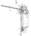
- the device according to the present invention provides for connecting a fuel filler 1 to the body panel 2 of a motor vehicle, said filler substantially comprising an end flange 3 and a cap 4.
- the device according to the present invention comprises a hollow body 5 having a bottom wall 6 in which is formed an opening housing the end of filler 1. Said end flange conveniently presents an annular groove 7 into which the edge of wall 6 is fitted.
- Hollow body 5 comprises a side wall 8, the end edge 9 of which is conveniently flange-shaped and connected to body panel 2.
- the device according to the present invention also comprises a supporting frame 13 connected to body panel 2 and to which is hinged a lid 14.
- flange 9 and frame 13 conveniently rest on the inner and outer surfaces respectively of panel 2, to which both are fitted by means of screws 15 (Fig.3).
- the device according to the present invention comprises at least one spring 16 for securing lid 14 in both the closed position shown in Fig.s 1 and 2 and the open position shown in Fig.3.
- Lid 14 conveniently presents a substantially C-shaped supporting shank 17 (Fig.s 2 and 3) projecting from the inner surface of lid 14.
- the end of said shank 17 presents a hole fitted through with a pin 18 inserted inside a respective seat formed, for example, inside an enlargement 19 (Fig.1) on frame 13.
- Spring 16 conveniently comprises one or more coils 22 from which project a pair of arms 23 and 24. Arm 23 is connected in a first location 25 close to the end of shank 17, and arm 24 in a second location 26 close to the end of a projection 27 on frame 13. Said spring 16 is assembled slightly preloaded, and locations 25 and 26 selected to ensure said lid 14 is secured in both the closed and open positions shown respectively in Fig.s 2 and 3.
- Pin 18 is conveniently housed inside an appendix 28 projecting laterally in relation to frame 13, as shown clearly in Fig.s 2 and 3, and therefore located behind and fully concealed by a portion 29 of body panel 2. Hollow body 5, frame 13 and lid 14 are preferably formed from plastic.
- the device according to the present invention is assembled quickly and easily by first mounting the assembly comprising frame 13, lid 14 and spring 16. As this is done on the workbench, said parts may be assembled quickly and accurately.
- Filler 1 to which hollow body 5 has already been fitted by inserting edge 6 inside annular groove 7, is then fitted to body panel 2 by simply placing edge 9 on the inner surface of panel 2 and securing it to the same, together with frame 13, by means of screws 15.
- Frame 13 is positioned as shown in the accompanying drawings by first inserting appendix 28 underneath portion 29 of body panel 2, by which said appendix 28 is fully concealed when assembled.
- Spring 16 normally secures lid 14 in the closed position shown in Fig.s 1 and 2.
- spring 16 provides for securing lid 14 in both the closed position against body panel 2, and in the fully-open position shown in Fig.3.
- the material from which the component parts of the device are formed, and the manner in which the same are fitted to body panel 2 prevent any possibility of oxidation, rusting, or local damage to the vehicle body.
- the design of the component parts of the device, and the manner in which they are assembled provide for a compact assembly, particularly on the inside of the vehicle body.
Landscapes
- Engineering & Computer Science (AREA)
- Life Sciences & Earth Sciences (AREA)
- Sustainable Development (AREA)
- Sustainable Energy (AREA)
- Chemical & Material Sciences (AREA)
- Combustion & Propulsion (AREA)
- Transportation (AREA)
- Mechanical Engineering (AREA)
- Cooling, Air Intake And Gas Exhaust, And Fuel Tank Arrangements In Propulsion Units (AREA)
Applications Claiming Priority (2)
| Application Number | Priority Date | Filing Date | Title |
|---|---|---|---|
| IT5369387U IT212210Z2 (it) | 1987-10-01 | 1987-10-01 | Zione del carburante nel serbatoio dispositivo di collegamento e didi un autoveicolo chiusura del bocchettone di introdu |
| IT5369387U | 1987-10-01 |
Publications (3)
| Publication Number | Publication Date |
|---|---|
| EP0310084A2 true EP0310084A2 (de) | 1989-04-05 |
| EP0310084A3 EP0310084A3 (en) | 1990-03-14 |
| EP0310084B1 EP0310084B1 (de) | 1992-04-15 |
Family
ID=11284625
Family Applications (1)
| Application Number | Title | Priority Date | Filing Date |
|---|---|---|---|
| EP19880116115 Expired EP0310084B1 (de) | 1987-10-01 | 1988-09-29 | Vorrichtung zur Befestigung und Sperrung einer Brandstoffeinfüllöffnung für Kraftfahrzeuge |
Country Status (5)
| Country | Link |
|---|---|
| EP (1) | EP0310084B1 (de) |
| BR (1) | BR8804468A (de) |
| DE (1) | DE3870128D1 (de) |
| ES (1) | ES2030815T3 (de) |
| IT (1) | IT212210Z2 (de) |
Cited By (2)
| Publication number | Priority date | Publication date | Assignee | Title |
|---|---|---|---|---|
| EP0548778A1 (de) * | 1991-12-20 | 1993-06-30 | FIAT AUTO S.p.A. | Verschlussdeckel für einen die Fülleinrichtung umfassenden Raum bei Fahrzeugen |
| JP2016193675A (ja) * | 2015-04-01 | 2016-11-17 | マツダ株式会社 | 車両のフィラーリッド部構造 |
Family Cites Families (2)
| Publication number | Priority date | Publication date | Assignee | Title |
|---|---|---|---|---|
| JPS5537739U (de) * | 1978-09-06 | 1980-03-11 | ||
| DE2922611A1 (de) * | 1979-06-02 | 1980-12-04 | Itw Ateco Gmbh | Einfuellstutzen fuer mit brennkraftmaschinen angetriebene fahrzeuge |
-
1987
- 1987-10-01 IT IT5369387U patent/IT212210Z2/it active
-
1988
- 1988-08-29 BR BR8804468A patent/BR8804468A/pt not_active IP Right Cessation
- 1988-09-29 DE DE88116115T patent/DE3870128D1/de not_active Expired - Fee Related
- 1988-09-29 ES ES88116115T patent/ES2030815T3/es not_active Expired - Lifetime
- 1988-09-29 EP EP19880116115 patent/EP0310084B1/de not_active Expired
Cited By (2)
| Publication number | Priority date | Publication date | Assignee | Title |
|---|---|---|---|---|
| EP0548778A1 (de) * | 1991-12-20 | 1993-06-30 | FIAT AUTO S.p.A. | Verschlussdeckel für einen die Fülleinrichtung umfassenden Raum bei Fahrzeugen |
| JP2016193675A (ja) * | 2015-04-01 | 2016-11-17 | マツダ株式会社 | 車両のフィラーリッド部構造 |
Also Published As
| Publication number | Publication date |
|---|---|
| IT8753693V0 (it) | 1987-10-01 |
| EP0310084A3 (en) | 1990-03-14 |
| IT212210Z2 (it) | 1989-07-04 |
| DE3870128D1 (en) | 1992-05-21 |
| BR8804468A (pt) | 1989-05-02 |
| ES2030815T3 (es) | 1992-11-16 |
| EP0310084B1 (de) | 1992-04-15 |
Similar Documents
| Publication | Publication Date | Title |
|---|---|---|
| US6098265A (en) | Setting fixture | |
| JPS602209B2 (ja) | シ−トバツクヒンジ | |
| US6601897B2 (en) | Vehicle interior panel having compartment and swing door | |
| US5306053A (en) | Hood prop rod with secondary latch | |
| US6244650B1 (en) | Support for the bonnet of a motor vehicle | |
| EP0310084B1 (de) | Vorrichtung zur Befestigung und Sperrung einer Brandstoffeinfüllöffnung für Kraftfahrzeuge | |
| JP4423612B2 (ja) | ドアガードバーの取付構造 | |
| US3711893A (en) | Vent window hinge | |
| JPS6113374Y2 (de) | ||
| JP3596311B2 (ja) | 開閉リッドの取付構造 | |
| JP3680503B2 (ja) | フューエルリッドの取付構造 | |
| EP0188317A2 (de) | Scharnierarm | |
| US2771629A (en) | Closure hinge | |
| JPH0129154Y2 (de) | ||
| JPH0748919Y2 (ja) | キャブオーバ型トラックのフロントリッドのロック装置 | |
| JPH0629152Y2 (ja) | ドアチエツクブラケツト取付け構造 | |
| JP3246126B2 (ja) | 自動車用アウトサイドハンドル構造 | |
| JP2586273B2 (ja) | オプション取付金具の嵌装構造 | |
| JPH0351208Y2 (de) | ||
| JPH043913Y2 (de) | ||
| KR0136959Y1 (ko) | 자동차용 연료 필러 도어 개폐장치 | |
| JPH035471Y2 (de) | ||
| KR100223530B1 (ko) | 자동차용 글로브 박스 | |
| JPH0114511Y2 (de) | ||
| KR200141609Y1 (ko) | 자동차 도어힌지의 장착구조 |
Legal Events
| Date | Code | Title | Description |
|---|---|---|---|
| PUAI | Public reference made under article 153(3) epc to a published international application that has entered the european phase |
Free format text: ORIGINAL CODE: 0009012 |
|
| AK | Designated contracting states |
Kind code of ref document: A2 Designated state(s): DE ES FR GB SE |
|
| PUAL | Search report despatched |
Free format text: ORIGINAL CODE: 0009013 |
|
| AK | Designated contracting states |
Kind code of ref document: A3 Designated state(s): DE ES FR GB SE |
|
| 17P | Request for examination filed |
Effective date: 19900904 |
|
| 17Q | First examination report despatched |
Effective date: 19910410 |
|
| GRAA | (expected) grant |
Free format text: ORIGINAL CODE: 0009210 |
|
| AK | Designated contracting states |
Kind code of ref document: B1 Designated state(s): DE ES FR GB SE |
|
| REF | Corresponds to: |
Ref document number: 3870128 Country of ref document: DE Date of ref document: 19920521 |
|
| ET | Fr: translation filed | ||
| REG | Reference to a national code |
Ref country code: ES Ref legal event code: FG2A Ref document number: 2030815 Country of ref document: ES Kind code of ref document: T3 |
|
| PLBE | No opposition filed within time limit |
Free format text: ORIGINAL CODE: 0009261 |
|
| STAA | Information on the status of an ep patent application or granted ep patent |
Free format text: STATUS: NO OPPOSITION FILED WITHIN TIME LIMIT |
|
| 26N | No opposition filed | ||
| EAL | Se: european patent in force in sweden |
Ref document number: 88116115.2 |
|
| PGFP | Annual fee paid to national office [announced via postgrant information from national office to epo] |
Ref country code: FR Payment date: 19970826 Year of fee payment: 10 |
|
| PGFP | Annual fee paid to national office [announced via postgrant information from national office to epo] |
Ref country code: SE Payment date: 19970916 Year of fee payment: 10 Ref country code: ES Payment date: 19970916 Year of fee payment: 10 |
|
| PGFP | Annual fee paid to national office [announced via postgrant information from national office to epo] |
Ref country code: GB Payment date: 19970922 Year of fee payment: 10 |
|
| PGFP | Annual fee paid to national office [announced via postgrant information from national office to epo] |
Ref country code: DE Payment date: 19971119 Year of fee payment: 10 |
|
| PG25 | Lapsed in a contracting state [announced via postgrant information from national office to epo] |
Ref country code: GB Free format text: LAPSE BECAUSE OF NON-PAYMENT OF DUE FEES Effective date: 19980929 |
|
| PG25 | Lapsed in a contracting state [announced via postgrant information from national office to epo] |
Ref country code: SE Free format text: LAPSE BECAUSE OF NON-PAYMENT OF DUE FEES Effective date: 19980930 Ref country code: ES Free format text: LAPSE BECAUSE OF EXPIRATION OF PROTECTION Effective date: 19980930 |
|
| GBPC | Gb: european patent ceased through non-payment of renewal fee |
Effective date: 19980929 |
|
| EUG | Se: european patent has lapsed |
Ref document number: 88116115.2 |
|
| PG25 | Lapsed in a contracting state [announced via postgrant information from national office to epo] |
Ref country code: FR Free format text: LAPSE BECAUSE OF NON-PAYMENT OF DUE FEES Effective date: 19990531 |
|
| PG25 | Lapsed in a contracting state [announced via postgrant information from national office to epo] |
Ref country code: DE Free format text: LAPSE BECAUSE OF NON-PAYMENT OF DUE FEES Effective date: 19990701 |
|
| REG | Reference to a national code |
Ref country code: FR Ref legal event code: ST |
|
| REG | Reference to a national code |
Ref country code: ES Ref legal event code: FD2A Effective date: 20010201 |