EP0310084A2 - Device for the connection and closure of a motor vehicle fuel filler - Google Patents
Device for the connection and closure of a motor vehicle fuel filler Download PDFInfo
- Publication number
- EP0310084A2 EP0310084A2 EP88116115A EP88116115A EP0310084A2 EP 0310084 A2 EP0310084 A2 EP 0310084A2 EP 88116115 A EP88116115 A EP 88116115A EP 88116115 A EP88116115 A EP 88116115A EP 0310084 A2 EP0310084 A2 EP 0310084A2
- Authority
- EP
- European Patent Office
- Prior art keywords
- frame
- lid
- fact
- spring
- body panel
- Prior art date
- Legal status (The legal status is an assumption and is not a legal conclusion. Google has not performed a legal analysis and makes no representation as to the accuracy of the status listed.)
- Granted
Links
Images


Classifications
-
- B—PERFORMING OPERATIONS; TRANSPORTING
- B60—VEHICLES IN GENERAL
- B60K—ARRANGEMENT OR MOUNTING OF PROPULSION UNITS OR OF TRANSMISSIONS IN VEHICLES; ARRANGEMENT OR MOUNTING OF PLURAL DIVERSE PRIME-MOVERS IN VEHICLES; AUXILIARY DRIVES FOR VEHICLES; INSTRUMENTATION OR DASHBOARDS FOR VEHICLES; ARRANGEMENTS IN CONNECTION WITH COOLING, AIR INTAKE, GAS EXHAUST OR FUEL SUPPLY OF PROPULSION UNITS IN VEHICLES
- B60K15/00—Arrangement in connection with fuel supply of combustion engines or other fuel consuming energy converters, e.g. fuel cells; Mounting or construction of fuel tanks
- B60K15/03—Fuel tanks
- B60K15/04—Tank inlets
- B60K15/05—Inlet covers
Definitions
- the present invention relates to a device for the connection and closure of a motor vehicle fuel filler, which device is designed to prevent oxidation of the bodywork in the vicinity of the filler, and to enable fast, troublefree assembly to the vehicle body.
- Fillers of the aforementioned type are known to comprise an end flange which is connected, usually welded, to the vehicle body with a tubular fitting inbetween.
- the body panel is also fitted with a lid for closing the cavity inside the said fitting, and which is also usually assembled by welding a hinge to the body panel, between this and the lid itself.
- the aim of the present invention is to provide a device for the connection and closure of a motor vehicle fuel filler, designed to overcome the aforementioned drawbacks, i.e. a device designed to prevent oxidation of the bodywork in the vicinity of the filler, and which is both compact and quick and easy to assemble.
- a device for the connection and closure of a motor vehicle fuel filler comprising an end flange connected to the vehicle body, and a cap; said device being characterised by the fact that it comprises a hollow body having a bottom wall connected to said flange and in which is formed an opening housing the end of said filler, and a side wall the end edge of which is connected to said body panel; a supporting frame also connected to said body panel and to which is hinged a lid; and at least one spring designed to secure said lid in a first closed position wherein it substantially rests on said frame, and in a second open position wherein the opening defined inside said frame is left exposed.
- the device according to the present invention provides for connecting a fuel filler 1 to the body panel 2 of a motor vehicle, said filler substantially comprising an end flange 3 and a cap 4.
- the device according to the present invention comprises a hollow body 5 having a bottom wall 6 in which is formed an opening housing the end of filler 1. Said end flange conveniently presents an annular groove 7 into which the edge of wall 6 is fitted.
- Hollow body 5 comprises a side wall 8, the end edge 9 of which is conveniently flange-shaped and connected to body panel 2.
- the device according to the present invention also comprises a supporting frame 13 connected to body panel 2 and to which is hinged a lid 14.
- flange 9 and frame 13 conveniently rest on the inner and outer surfaces respectively of panel 2, to which both are fitted by means of screws 15 (Fig.3).
- the device according to the present invention comprises at least one spring 16 for securing lid 14 in both the closed position shown in Fig.s 1 and 2 and the open position shown in Fig.3.
- Lid 14 conveniently presents a substantially C-shaped supporting shank 17 (Fig.s 2 and 3) projecting from the inner surface of lid 14.
- the end of said shank 17 presents a hole fitted through with a pin 18 inserted inside a respective seat formed, for example, inside an enlargement 19 (Fig.1) on frame 13.
- Spring 16 conveniently comprises one or more coils 22 from which project a pair of arms 23 and 24. Arm 23 is connected in a first location 25 close to the end of shank 17, and arm 24 in a second location 26 close to the end of a projection 27 on frame 13. Said spring 16 is assembled slightly preloaded, and locations 25 and 26 selected to ensure said lid 14 is secured in both the closed and open positions shown respectively in Fig.s 2 and 3.
- Pin 18 is conveniently housed inside an appendix 28 projecting laterally in relation to frame 13, as shown clearly in Fig.s 2 and 3, and therefore located behind and fully concealed by a portion 29 of body panel 2. Hollow body 5, frame 13 and lid 14 are preferably formed from plastic.
- the device according to the present invention is assembled quickly and easily by first mounting the assembly comprising frame 13, lid 14 and spring 16. As this is done on the workbench, said parts may be assembled quickly and accurately.
- Filler 1 to which hollow body 5 has already been fitted by inserting edge 6 inside annular groove 7, is then fitted to body panel 2 by simply placing edge 9 on the inner surface of panel 2 and securing it to the same, together with frame 13, by means of screws 15.
- Frame 13 is positioned as shown in the accompanying drawings by first inserting appendix 28 underneath portion 29 of body panel 2, by which said appendix 28 is fully concealed when assembled.
- Spring 16 normally secures lid 14 in the closed position shown in Fig.s 1 and 2.
- spring 16 provides for securing lid 14 in both the closed position against body panel 2, and in the fully-open position shown in Fig.3.
- the material from which the component parts of the device are formed, and the manner in which the same are fitted to body panel 2 prevent any possibility of oxidation, rusting, or local damage to the vehicle body.
- the design of the component parts of the device, and the manner in which they are assembled provide for a compact assembly, particularly on the inside of the vehicle body.
Landscapes
- Engineering & Computer Science (AREA)
- Life Sciences & Earth Sciences (AREA)
- Sustainable Development (AREA)
- Sustainable Energy (AREA)
- Chemical & Material Sciences (AREA)
- Combustion & Propulsion (AREA)
- Transportation (AREA)
- Mechanical Engineering (AREA)
- Cooling, Air Intake And Gas Exhaust, And Fuel Tank Arrangements In Propulsion Units (AREA)
Abstract
Description
- The present invention relates to a device for the connection and closure of a motor vehicle fuel filler, which device is designed to prevent oxidation of the bodywork in the vicinity of the filler, and to enable fast, troublefree assembly to the vehicle body.
- Fillers of the aforementioned type are known to comprise an end flange which is connected, usually welded, to the vehicle body with a tubular fitting inbetween. The body panel is also fitted with a lid for closing the cavity inside the said fitting, and which is also usually assembled by welding a hinge to the body panel, between this and the lid itself.
- Fillers of the aforementioned type present a number of major drawbacks: rapid oxidation due to welding of the aforementioned parts; assembly difficulties due to limited access to the body parts involved; and, finally, the formation of a cumbersome assembly inside the vehicle bodywork.
- The aim of the present invention is to provide a device for the connection and closure of a motor vehicle fuel filler, designed to overcome the aforementioned drawbacks, i.e. a device designed to prevent oxidation of the bodywork in the vicinity of the filler, and which is both compact and quick and easy to assemble. With this aim in view, according to the present invention, there is provided a device for the connection and closure of a motor vehicle fuel filler comprising an end flange connected to the vehicle body, and a cap; said device being characterised by the fact that it comprises a hollow body having a bottom wall connected to said flange and in which is formed an opening housing the end of said filler, and a side wall the end edge of which is connected to said body panel; a supporting frame also connected to said body panel and to which is hinged a lid; and at least one spring designed to secure said lid in a first closed position wherein it substantially rests on said frame, and in a second open position wherein the opening defined inside said frame is left exposed.
- One embodiment of the present invention will be described with reference to the accompanying drawings, in which:
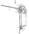
- Fig.1 shows a vertical section of the device according to the present invention;
- Fig.2 shows a section of the Fig.1 device in the closed position, and perpendicular to the Fig.1 section;
- Fig.3 shows a section of the Fig.2 device in the open position.
- The device according to the present invention provides for connecting a fuel filler 1 to the
body panel 2 of a motor vehicle, said filler substantially comprising an end flange 3 and a cap 4. The device according to the present invention comprises ahollow body 5 having a bottom wall 6 in which is formed an opening housing the end of filler 1. Said end flange conveniently presents an annular groove 7 into which the edge of wall 6 is fitted.Hollow body 5 comprises a side wall 8, theend edge 9 of which is conveniently flange-shaped and connected tobody panel 2. - The device according to the present invention also comprises a supporting
frame 13 connected tobody panel 2 and to which is hinged alid 14. As shown clearly in the accompanying drawings,flange 9 andframe 13 conveniently rest on the inner and outer surfaces respectively ofpanel 2, to which both are fitted by means of screws 15 (Fig.3). The device according to the present invention comprises at least onespring 16 for securinglid 14 in both the closed position shown in Fig.s 1 and 2 and the open position shown in Fig.3.Lid 14 conveniently presents a substantially C-shaped supporting shank 17 (Fig.s 2 and 3) projecting from the inner surface oflid 14. The end of saidshank 17 presents a hole fitted through with apin 18 inserted inside a respective seat formed, for example, inside an enlargement 19 (Fig.1) onframe 13. -
Spring 16 conveniently comprises one ormore coils 22 from which project a pair ofarms Arm 23 is connected in afirst location 25 close to the end ofshank 17, andarm 24 in asecond location 26 close to the end of aprojection 27 onframe 13. Saidspring 16 is assembled slightly preloaded, andlocations lid 14 is secured in both the closed and open positions shown respectively in Fig.s 2 and 3.Pin 18 is conveniently housed inside anappendix 28 projecting laterally in relation toframe 13, as shown clearly in Fig.s 2 and 3, and therefore located behind and fully concealed by aportion 29 ofbody panel 2.Hollow body 5,frame 13 andlid 14 are preferably formed from plastic. - The device according to the present invention is assembled quickly and easily by first mounting the
assembly comprising frame 13,lid 14 andspring 16. As this is done on the workbench, said parts may be assembled quickly and accurately. Filler 1, to whichhollow body 5 has already been fitted by inserting edge 6 inside annular groove 7, is then fitted tobody panel 2 by simply placingedge 9 on the inner surface ofpanel 2 and securing it to the same, together withframe 13, by means ofscrews 15.Frame 13 is positioned as shown in the accompanying drawings by first insertingappendix 28underneath portion 29 ofbody panel 2, by which saidappendix 28 is fully concealed when assembled.Spring 16 normally secureslid 14 in the closed position shown in Fig.s 1 and 2. By virtue of the preload onspring 16 and theassembly locations arms spring 16 provides for securinglid 14 in both the closed position againstbody panel 2, and in the fully-open position shown in Fig.3. - Clearly, the material from which the component parts of the device are formed, and the manner in which the same are fitted to
body panel 2, prevent any possibility of oxidation, rusting, or local damage to the vehicle body. Also, the design of the component parts of the device, and the manner in which they are assembled, provide for a compact assembly, particularly on the inside of the vehicle body. - To those skilled in the art it will be clear that changes may be made to both the design and arrangement of the component parts of the device as described and illustrated herein without, however, departing from the scope of the present invention.
Claims (7)
Applications Claiming Priority (2)
| Application Number | Priority Date | Filing Date | Title |
|---|---|---|---|
| IT5369387U IT212210Z2 (en) | 1987-10-01 | 1987-10-01 | TION OF THE FUEL IN THE TANK CONNECTION DEVICE AND DIDI A VEHICLE CLOSING THE INTRODU |
| IT5369387U | 1987-10-01 |
Publications (3)
| Publication Number | Publication Date |
|---|---|
| EP0310084A2 true EP0310084A2 (en) | 1989-04-05 |
| EP0310084A3 EP0310084A3 (en) | 1990-03-14 |
| EP0310084B1 EP0310084B1 (en) | 1992-04-15 |
Family
ID=11284625
Family Applications (1)
| Application Number | Title | Priority Date | Filing Date |
|---|---|---|---|
| EP19880116115 Expired EP0310084B1 (en) | 1987-10-01 | 1988-09-29 | Device for the connection and closure of a motor vehicle fuel filler |
Country Status (5)
| Country | Link |
|---|---|
| EP (1) | EP0310084B1 (en) |
| BR (1) | BR8804468A (en) |
| DE (1) | DE3870128D1 (en) |
| ES (1) | ES2030815T3 (en) |
| IT (1) | IT212210Z2 (en) |
Cited By (2)
| Publication number | Priority date | Publication date | Assignee | Title |
|---|---|---|---|---|
| EP0548778A1 (en) * | 1991-12-20 | 1993-06-30 | FIAT AUTO S.p.A. | Screening means for a space housing the filler pipe of a vehicle |
| JP2016193675A (en) * | 2015-04-01 | 2016-11-17 | マツダ株式会社 | Filler lid part structure of vehicle |
Citations (2)
| Publication number | Priority date | Publication date | Assignee | Title |
|---|---|---|---|---|
| FR2435367A1 (en) * | 1978-09-06 | 1980-04-04 | Nissan Motor | FUEL FILLING PORT FOR A MOTOR VEHICLE |
| DE2922611A1 (en) * | 1979-06-02 | 1980-12-04 | Itw Ateco Gmbh | FUEL CONNECTOR FOR VEHICLES DRIVEN WITH INTERNAL COMBUSTION ENGINES |
-
1987
- 1987-10-01 IT IT5369387U patent/IT212210Z2/en active
-
1988
- 1988-08-29 BR BR8804468A patent/BR8804468A/en not_active IP Right Cessation
- 1988-09-29 DE DE88116115T patent/DE3870128D1/en not_active Expired - Fee Related
- 1988-09-29 ES ES88116115T patent/ES2030815T3/en not_active Expired - Lifetime
- 1988-09-29 EP EP19880116115 patent/EP0310084B1/en not_active Expired
Patent Citations (2)
| Publication number | Priority date | Publication date | Assignee | Title |
|---|---|---|---|---|
| FR2435367A1 (en) * | 1978-09-06 | 1980-04-04 | Nissan Motor | FUEL FILLING PORT FOR A MOTOR VEHICLE |
| DE2922611A1 (en) * | 1979-06-02 | 1980-12-04 | Itw Ateco Gmbh | FUEL CONNECTOR FOR VEHICLES DRIVEN WITH INTERNAL COMBUSTION ENGINES |
Cited By (2)
| Publication number | Priority date | Publication date | Assignee | Title |
|---|---|---|---|---|
| EP0548778A1 (en) * | 1991-12-20 | 1993-06-30 | FIAT AUTO S.p.A. | Screening means for a space housing the filler pipe of a vehicle |
| JP2016193675A (en) * | 2015-04-01 | 2016-11-17 | マツダ株式会社 | Filler lid part structure of vehicle |
Also Published As
| Publication number | Publication date |
|---|---|
| EP0310084A3 (en) | 1990-03-14 |
| IT8753693V0 (en) | 1987-10-01 |
| DE3870128D1 (en) | 1992-05-21 |
| EP0310084B1 (en) | 1992-04-15 |
| IT212210Z2 (en) | 1989-07-04 |
| ES2030815T3 (en) | 1992-11-16 |
| BR8804468A (en) | 1989-05-02 |
Similar Documents
| Publication | Publication Date | Title |
|---|---|---|
| JP4423612B2 (en) | Door guard bar mounting structure | |
| US6098265A (en) | Setting fixture | |
| US6244650B1 (en) | Support for the bonnet of a motor vehicle | |
| EP0310084B1 (en) | Device for the connection and closure of a motor vehicle fuel filler | |
| US3711893A (en) | Vent window hinge | |
| JPH0347090Y2 (en) | ||
| JP3596311B2 (en) | Opening / closing lid mounting structure | |
| JP3855325B2 (en) | Striker part positioning method and positioning device for opening / closing member | |
| EP0188317A2 (en) | Hinge leaf | |
| JPH0129154Y2 (en) | ||
| JP2766539B2 (en) | Car console box | |
| JPH0748919Y2 (en) | Locking device for front lid of cab-over truck | |
| JPH0629152Y2 (en) | Door check bracket mounting structure | |
| JP3246126B2 (en) | Outside handle structure for automobiles | |
| JP2586273B2 (en) | Fitting structure of optional mounting bracket | |
| US2795472A (en) | Cabinet door hinge mechanism | |
| JPH0351208Y2 (en) | ||
| JPH035471Y2 (en) | ||
| KR100223530B1 (en) | Glove box for an automobile | |
| JPH0114511Y2 (en) | ||
| KR19980035430U (en) | Rear seat mounting structure | |
| KR0120174B1 (en) | Connecting structure of front pillar and dash panel | |
| JPH023726B2 (en) | ||
| US1616803A (en) | Connecting means for two-part automobile doors | |
| JPH0125084Y2 (en) |
Legal Events
| Date | Code | Title | Description |
|---|---|---|---|
| PUAI | Public reference made under article 153(3) epc to a published international application that has entered the european phase |
Free format text: ORIGINAL CODE: 0009012 |
|
| AK | Designated contracting states |
Kind code of ref document: A2 Designated state(s): DE ES FR GB SE |
|
| PUAL | Search report despatched |
Free format text: ORIGINAL CODE: 0009013 |
|
| AK | Designated contracting states |
Kind code of ref document: A3 Designated state(s): DE ES FR GB SE |
|
| 17P | Request for examination filed |
Effective date: 19900904 |
|
| 17Q | First examination report despatched |
Effective date: 19910410 |
|
| GRAA | (expected) grant |
Free format text: ORIGINAL CODE: 0009210 |
|
| AK | Designated contracting states |
Kind code of ref document: B1 Designated state(s): DE ES FR GB SE |
|
| REF | Corresponds to: |
Ref document number: 3870128 Country of ref document: DE Date of ref document: 19920521 |
|
| ET | Fr: translation filed | ||
| REG | Reference to a national code |
Ref country code: ES Ref legal event code: FG2A Ref document number: 2030815 Country of ref document: ES Kind code of ref document: T3 |
|
| PLBE | No opposition filed within time limit |
Free format text: ORIGINAL CODE: 0009261 |
|
| STAA | Information on the status of an ep patent application or granted ep patent |
Free format text: STATUS: NO OPPOSITION FILED WITHIN TIME LIMIT |
|
| 26N | No opposition filed | ||
| EAL | Se: european patent in force in sweden |
Ref document number: 88116115.2 |
|
| PGFP | Annual fee paid to national office [announced via postgrant information from national office to epo] |
Ref country code: FR Payment date: 19970826 Year of fee payment: 10 |
|
| PGFP | Annual fee paid to national office [announced via postgrant information from national office to epo] |
Ref country code: SE Payment date: 19970916 Year of fee payment: 10 Ref country code: ES Payment date: 19970916 Year of fee payment: 10 |
|
| PGFP | Annual fee paid to national office [announced via postgrant information from national office to epo] |
Ref country code: GB Payment date: 19970922 Year of fee payment: 10 |
|
| PGFP | Annual fee paid to national office [announced via postgrant information from national office to epo] |
Ref country code: DE Payment date: 19971119 Year of fee payment: 10 |
|
| PG25 | Lapsed in a contracting state [announced via postgrant information from national office to epo] |
Ref country code: GB Free format text: LAPSE BECAUSE OF NON-PAYMENT OF DUE FEES Effective date: 19980929 |
|
| PG25 | Lapsed in a contracting state [announced via postgrant information from national office to epo] |
Ref country code: SE Free format text: LAPSE BECAUSE OF NON-PAYMENT OF DUE FEES Effective date: 19980930 Ref country code: ES Free format text: LAPSE BECAUSE OF EXPIRATION OF PROTECTION Effective date: 19980930 |
|
| GBPC | Gb: european patent ceased through non-payment of renewal fee |
Effective date: 19980929 |
|
| EUG | Se: european patent has lapsed |
Ref document number: 88116115.2 |
|
| PG25 | Lapsed in a contracting state [announced via postgrant information from national office to epo] |
Ref country code: FR Free format text: LAPSE BECAUSE OF NON-PAYMENT OF DUE FEES Effective date: 19990531 |
|
| PG25 | Lapsed in a contracting state [announced via postgrant information from national office to epo] |
Ref country code: DE Free format text: LAPSE BECAUSE OF NON-PAYMENT OF DUE FEES Effective date: 19990701 |
|
| REG | Reference to a national code |
Ref country code: FR Ref legal event code: ST |
|
| REG | Reference to a national code |
Ref country code: ES Ref legal event code: FD2A Effective date: 20010201 |