EP0309319B1 - Installation de refroidissement d'un produit extrudé en continu - Google Patents
Installation de refroidissement d'un produit extrudé en continu Download PDFInfo
- Publication number
- EP0309319B1 EP0309319B1 EP88402323A EP88402323A EP0309319B1 EP 0309319 B1 EP0309319 B1 EP 0309319B1 EP 88402323 A EP88402323 A EP 88402323A EP 88402323 A EP88402323 A EP 88402323A EP 0309319 B1 EP0309319 B1 EP 0309319B1
- Authority
- EP
- European Patent Office
- Prior art keywords
- installation according
- cryogenic fluid
- product
- zone
- central zone
- Prior art date
- Legal status (The legal status is an assumption and is not a legal conclusion. Google has not performed a legal analysis and makes no representation as to the accuracy of the status listed.)
- Expired - Lifetime
Links
- 238000001816 cooling Methods 0.000 title claims description 21
- 235000012438 extruded product Nutrition 0.000 title 1
- 239000012530 fluid Substances 0.000 claims description 23
- 238000009434 installation Methods 0.000 claims description 20
- 238000011144 upstream manufacturing Methods 0.000 claims description 10
- 239000007788 liquid Substances 0.000 claims description 7
- 239000007787 solid Substances 0.000 claims description 7
- 238000005507 spraying Methods 0.000 claims description 6
- CURLTUGMZLYLDI-UHFFFAOYSA-N Carbon dioxide Chemical compound O=C=O CURLTUGMZLYLDI-UHFFFAOYSA-N 0.000 claims description 4
- 239000007921 spray Substances 0.000 claims description 3
- IJGRMHOSHXDMSA-UHFFFAOYSA-N Atomic nitrogen Chemical compound N#N IJGRMHOSHXDMSA-UHFFFAOYSA-N 0.000 claims description 2
- 229910002092 carbon dioxide Inorganic materials 0.000 claims description 2
- 239000001569 carbon dioxide Substances 0.000 claims description 2
- JCXJVPUVTGWSNB-UHFFFAOYSA-N nitrogen dioxide Inorganic materials O=[N]=O JCXJVPUVTGWSNB-UHFFFAOYSA-N 0.000 claims description 2
- 239000007789 gas Substances 0.000 description 9
- 238000001125 extrusion Methods 0.000 description 4
- 239000000463 material Substances 0.000 description 4
- 235000014510 cooky Nutrition 0.000 description 3
- 238000009826 distribution Methods 0.000 description 3
- 230000001174 ascending effect Effects 0.000 description 2
- 238000005520 cutting process Methods 0.000 description 2
- 235000013305 food Nutrition 0.000 description 2
- VNWKTOKETHGBQD-UHFFFAOYSA-N methane Chemical compound C VNWKTOKETHGBQD-UHFFFAOYSA-N 0.000 description 2
- 239000004033 plastic Substances 0.000 description 2
- 238000007789 sealing Methods 0.000 description 2
- 238000011282 treatment Methods 0.000 description 2
- 238000009825 accumulation Methods 0.000 description 1
- 238000006243 chemical reaction Methods 0.000 description 1
- 239000011248 coating agent Substances 0.000 description 1
- 238000000576 coating method Methods 0.000 description 1
- 239000011152 fibreglass Substances 0.000 description 1
- 238000011049 filling Methods 0.000 description 1
- 239000011810 insulating material Substances 0.000 description 1
- 238000012423 maintenance Methods 0.000 description 1
- 238000004519 manufacturing process Methods 0.000 description 1
- 238000000034 method Methods 0.000 description 1
- 239000003345 natural gas Substances 0.000 description 1
- 238000004806 packaging method and process Methods 0.000 description 1
- 229920001296 polysiloxane Polymers 0.000 description 1
- 230000001737 promoting effect Effects 0.000 description 1
- 230000000284 resting effect Effects 0.000 description 1
- 230000006641 stabilisation Effects 0.000 description 1
- 238000011105 stabilization Methods 0.000 description 1
- 238000003756 stirring Methods 0.000 description 1
- 238000000859 sublimation Methods 0.000 description 1
- 230000008022 sublimation Effects 0.000 description 1
Images
Classifications
-
- F—MECHANICAL ENGINEERING; LIGHTING; HEATING; WEAPONS; BLASTING
- F25—REFRIGERATION OR COOLING; COMBINED HEATING AND REFRIGERATION SYSTEMS; HEAT PUMP SYSTEMS; MANUFACTURE OR STORAGE OF ICE; LIQUEFACTION SOLIDIFICATION OF GASES
- F25D—REFRIGERATORS; COLD ROOMS; ICE-BOXES; COOLING OR FREEZING APPARATUS NOT OTHERWISE PROVIDED FOR
- F25D3/00—Devices using other cold materials; Devices using cold-storage bodies
- F25D3/10—Devices using other cold materials; Devices using cold-storage bodies using liquefied gases, e.g. liquid air
- F25D3/11—Devices using other cold materials; Devices using cold-storage bodies using liquefied gases, e.g. liquid air with conveyors carrying articles to be cooled through the cooling space
-
- B—PERFORMING OPERATIONS; TRANSPORTING
- B29—WORKING OF PLASTICS; WORKING OF SUBSTANCES IN A PLASTIC STATE IN GENERAL
- B29C—SHAPING OR JOINING OF PLASTICS; SHAPING OF MATERIAL IN A PLASTIC STATE, NOT OTHERWISE PROVIDED FOR; AFTER-TREATMENT OF THE SHAPED PRODUCTS, e.g. REPAIRING
- B29C48/00—Extrusion moulding, i.e. expressing the moulding material through a die or nozzle which imparts the desired form; Apparatus therefor
- B29C48/03—Extrusion moulding, i.e. expressing the moulding material through a die or nozzle which imparts the desired form; Apparatus therefor characterised by the shape of the extruded material at extrusion
- B29C48/06—Rod-shaped
-
- B—PERFORMING OPERATIONS; TRANSPORTING
- B29—WORKING OF PLASTICS; WORKING OF SUBSTANCES IN A PLASTIC STATE IN GENERAL
- B29C—SHAPING OR JOINING OF PLASTICS; SHAPING OF MATERIAL IN A PLASTIC STATE, NOT OTHERWISE PROVIDED FOR; AFTER-TREATMENT OF THE SHAPED PRODUCTS, e.g. REPAIRING
- B29C48/00—Extrusion moulding, i.e. expressing the moulding material through a die or nozzle which imparts the desired form; Apparatus therefor
- B29C48/25—Component parts, details or accessories; Auxiliary operations
- B29C48/88—Thermal treatment of the stream of extruded material, e.g. cooling
- B29C48/90—Thermal treatment of the stream of extruded material, e.g. cooling with calibration or sizing, i.e. combined with fixing or setting of the final dimensions of the extruded article
-
- B—PERFORMING OPERATIONS; TRANSPORTING
- B29—WORKING OF PLASTICS; WORKING OF SUBSTANCES IN A PLASTIC STATE IN GENERAL
- B29C—SHAPING OR JOINING OF PLASTICS; SHAPING OF MATERIAL IN A PLASTIC STATE, NOT OTHERWISE PROVIDED FOR; AFTER-TREATMENT OF THE SHAPED PRODUCTS, e.g. REPAIRING
- B29C48/00—Extrusion moulding, i.e. expressing the moulding material through a die or nozzle which imparts the desired form; Apparatus therefor
- B29C48/25—Component parts, details or accessories; Auxiliary operations
- B29C48/88—Thermal treatment of the stream of extruded material, e.g. cooling
- B29C48/911—Cooling
-
- B—PERFORMING OPERATIONS; TRANSPORTING
- B29—WORKING OF PLASTICS; WORKING OF SUBSTANCES IN A PLASTIC STATE IN GENERAL
- B29C—SHAPING OR JOINING OF PLASTICS; SHAPING OF MATERIAL IN A PLASTIC STATE, NOT OTHERWISE PROVIDED FOR; AFTER-TREATMENT OF THE SHAPED PRODUCTS, e.g. REPAIRING
- B29C48/00—Extrusion moulding, i.e. expressing the moulding material through a die or nozzle which imparts the desired form; Apparatus therefor
- B29C48/03—Extrusion moulding, i.e. expressing the moulding material through a die or nozzle which imparts the desired form; Apparatus therefor characterised by the shape of the extruded material at extrusion
- B29C48/07—Flat, e.g. panels
-
- B—PERFORMING OPERATIONS; TRANSPORTING
- B29—WORKING OF PLASTICS; WORKING OF SUBSTANCES IN A PLASTIC STATE IN GENERAL
- B29C—SHAPING OR JOINING OF PLASTICS; SHAPING OF MATERIAL IN A PLASTIC STATE, NOT OTHERWISE PROVIDED FOR; AFTER-TREATMENT OF THE SHAPED PRODUCTS, e.g. REPAIRING
- B29C48/00—Extrusion moulding, i.e. expressing the moulding material through a die or nozzle which imparts the desired form; Apparatus therefor
- B29C48/25—Component parts, details or accessories; Auxiliary operations
- B29C48/88—Thermal treatment of the stream of extruded material, e.g. cooling
- B29C48/90—Thermal treatment of the stream of extruded material, e.g. cooling with calibration or sizing, i.e. combined with fixing or setting of the final dimensions of the extruded article
- B29C48/905—Thermal treatment of the stream of extruded material, e.g. cooling with calibration or sizing, i.e. combined with fixing or setting of the final dimensions of the extruded article using wet calibration, i.e. in a quenching tank
-
- F—MECHANICAL ENGINEERING; LIGHTING; HEATING; WEAPONS; BLASTING
- F25—REFRIGERATION OR COOLING; COMBINED HEATING AND REFRIGERATION SYSTEMS; HEAT PUMP SYSTEMS; MANUFACTURE OR STORAGE OF ICE; LIQUEFACTION SOLIDIFICATION OF GASES
- F25D—REFRIGERATORS; COLD ROOMS; ICE-BOXES; COOLING OR FREEZING APPARATUS NOT OTHERWISE PROVIDED FOR
- F25D2400/00—General features of, or devices for refrigerators, cold rooms, ice-boxes, or for cooling or freezing apparatus not covered by any other subclass
- F25D2400/28—Quick cooling
Definitions
- the present invention relates to an installation for continuously cooling an extruded or formed product of elongated shape, of the type comprising an elongated box with thermally insulated walls defining an internal path comprising an upstream zone, a central zone and a downstream zone, a means for transporting the product along the path, the central zone comprising a means for projecting cryogenic fluid onto the path of the product.
- the object of the present invention is to provide a cooling installation of simple structure, advantageously modular, allowing, for final consumption of cryogenic fluid, cooling of simple structure, advantageously modular optimum and at a rapid cooling rate, at least equal to the continuous manufacturing speed of the elongated product, advantageously cooled directly at the outlet of an extruder or a extruder.
- the path is rectilinear and defined in a U-shaped bottom structure forming a gutter of small section in which extends a conveyor belt constituting the means of transport and which is tightly closed by an upper structure forming a removable cover, and in that the structure of the central zone comprises means for spraying the cryogenic fluid in liquid or solid form towards the conveyor belt.
- the product undergoes, in the central zone, a sudden cooling by contact with the cryogenic fluid sprayed in liquid or solid form, the cooling being initiated, in the upstream zone, by convection with the expanded cryogenic fluid coming from the central area, and gradually terminated in the downstream area, by convection co-current with the expanded cryogenic gas coming from the central area, the small cross-section of the gas passage in the upstream and downstream areas promoting a natural gas setting allowing, with reduced quantities of cryogenic fluid, optimal heat exchanges with the product, even if the latter is moving at a relatively high speed.
- the cooling zones according to the invention are devoid of mechanical means for stirring the gas, in order to ensure easy and rapid flow of the cold gas along the co- or counter-current products, the internal section of the U of the box must be adapted to the size of the product formed or extruded to be cooled, and typically represents approximately 5 to 30 times, more particularly 11 to 15 times, the section of the product.
- nitrogen or carbon dioxide may be used as sprayed cryogenic fluid according to the invention.
- the fluid is in solid or liquid form after spraying and before sublimation.
- the invention applies particularly to products coextruded in the food industry, where it is necessary to intervene quickly to cool the external material and the lining, failing which the subsequent treatments, of the cutting type, are difficult; in addition, partial external cooling is not enough, because taking into account the thermal coefficients, the lining tends to remain hot, and to heat the assembly.
- the invention is applicable in other fields of industry, for example in the field of products formed under pressure.
- the length of the conversion and / or stabilization zones, and the flow rate of cryogenic fluid are chosen as a function of the temperature of the extruded or coextruded product, its extrusion speed, the thermal coefficients of the product (s) (co-) extruded (s) and maximum temperature for subsequent handling.
- the device according to the invention and the installation can be implemented and provided downstream of an extruder or forming machine producing several parallel products or downstream of several extruders or forming machines. Products are treated the same way. It is then possible to provide a wide continuous strip or several parallel continuous strips, the total width of which is substantially the same width as the internal width of the box.
- the cooling is ensured by the gas coming from the expansion of the fluid, by convection.
- the small gas passage section allows the gas to speed up, which reaches a sufficient value for sufficient convection. It therefore appears particularly important that the seal is made, between the cover and the bottom of the body and between the portions, to avoid loss of gas and therefore of flow speed.
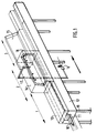
- the tunnel shown in Figure 1 is intended for continuous cooling of a coextruded product continuously from an extruder not shown upstream of the tunnel in the direction of extrusion (indicated by an arrow).
- This horizontal tunnel of generally elongated rectangular section has three zones or portions 1,2,3.
- the product 10 rests on a strip 11 disposed at the bottom of the tunnel substantially the same width as the interior width of the tunnel.
- This strip is driven in continuous translation by means not shown, of the drive drum type driven by a motor.
- the strip 11 can be made of fiberglass material covered with silicone, but any other flexible material that is not sticky to the product at low temperature can be used.
- the tunnel consists of a bottom 12 with a U-shaped section, forming a gutter, through which the strip 11 passes, the different portions 1,2,3 being determined by the cover (13,14,15) closing the box with a tight seal.
- the walls of the bottom 12 and the covers 13,14,15 are made of thermally insulating material, used in the usual way for cooling equipment.
- the covers are simple flat walls; and the spray cooling zone 2 comprises a box-shaped cover 14.
- the zone 2 comprises a flat cover equipped with the distribution means.
- a source of cryogenic fluid feeds, through a solenoid valve 16, a pipe 17 leading the cryogenic fluid to the distribution ramp 18 by nozzles inside the box 14.
- the ramp 18 can also simply be perforated for the distribution of the fluid.
- the covers are hinged along the box using hinges not shown; the cover 13 is shown in the closed position, the 15 in the open position.
- the entire tunnel rests on feet 19, the height of which is adapted or adaptable to the exit height of the extruder.
- V-shaped seals can be provided on either side of the free passage of the tunnel, plastic or elastic tubular seals wedged between two stops outside the box.
- a double gasket system is used to ensure complete tightness in cold gas.
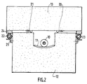
- FIG. 2 appear the U-shaped box 12, and the cover 13 resting on a double system of seals.
- V-joints 20,21 preferably metallic, which remain flexible in the cold are arranged between the cover and the upper walls of the U-shaped casing.
- cylindrical plastic seals 22,23 which seal by crushing between a stop 24 fixed on the cover and a support 25 fixed to the box.
- Slicing temperatures should be 60 ° C outside and 40-50 ° C inside.
- the diameter of the cookie is 13 to 14 mm, and that of the filling 10 mm.
- the cooling is carried out with an installation as described in FIG. 1, the length of zone 1 being 1 m, of zone 2 of 2 m and of zone 3 of 5 m, the passage section being 4x5 cm2.
- the material consumes 85 to 100 l / h of LN2.
- the device can be used for cookies extruded or formed under pressure.
Landscapes
- Engineering & Computer Science (AREA)
- Mechanical Engineering (AREA)
- Physics & Mathematics (AREA)
- Thermal Sciences (AREA)
- Chemical & Material Sciences (AREA)
- Combustion & Propulsion (AREA)
- General Engineering & Computer Science (AREA)
- Formation And Processing Of Food Products (AREA)
- Extrusion Moulding Of Plastics Or The Like (AREA)
Description
- La présente invention concerne une installation de refroidissement en continu d'un produit extrudé ou formé de forme allongée, du type comprenant un caisson allongé à parois thermiquement isolées définissant un trajet intérieur comportant une zone amont, une zone centrale et une zone aval, un moyen de transport du produit le long du trajet, la zone centrale comportant un moyen de projection de fluide cryogénique sur le trajet du produit.
- Une installation de refroidissement du type défini ci-dessus est décrite dans le document EP-A-0.084.683. Dans ce document, la zone aval est ascendante et munie d'un moyen de transport à vitesse augmentée, le refroidissement s'effectuant pour l'essentiel dans les zones centrale et amont dont l'ouverture d'entrée est typiquement surélevée par rapport au niveau de ces zones centrale et amont de façon à favoriser un maintien prononcé du fluide cryogénique vaporisé dans ces zones. De ce fait, tant les zones centrale et amont que la zone aval, ascendante, sont largement dimensionnées transversalement.
- La présente invention a pour objet de proposer une installation de refroidissement de structure simple, avantageusement modulaire, permettant, pour une consommation finale de fluide cryogénique, un refroidissement de structure simple, avantageusement modulaire optimum et à une vitesse rapide de refroidissement, au moins égale à la vitesse de fabrication en continu du produit de forme allongée, avantageusement refroidi directement en sortie d'une extrudeuse ou d'une boudineuse.
- Pour ce faire, dans l'installation selon l'invention, le trajet est rectiligne et défini dans une structure de fond en forme de U formant une gouttière de faible section dans laquelle s'étend une bande convoyeuse constituant le moyen de transport et qui est fermée de façon étanche par une structure supérieure formant couvercle amovible, et en ce que la structure de la zone centrale comporte un moyen de pulvérisation du fluide cryogénique sous forme liquide ou solide vers la bande convoyeuse.
- Avec l'installation selon l'invention, le produit subit, dans la zone centrale, un refroidissement brusque par contact avec le fluide cryogénique pulvérisé sous forme liquide ou solide, le refroidissement étant initié, dans la zone amont, par convection avec le fluide cryogénique détendu provenant de la zone centrale, et terminé progressivement dans la zone aval, par convection à co-courant avec le gaz cryogénique détendu provenant de la zone centrale, la faible section de passage du gaz dans les zones amont et aval favorisant une mise en vitesse naturelle du gaz permettant, avec des quantités réduites de fluide cryogénique, des échanges thermiques optimaux avec le produit, même si celui-ci se déplace à une vitesse relativement importante.
- Le document FR-A-2.160.319 décrit une installation de refroidissement où le fluide cryogénique passe tout d'abord dans une série d'échangeurs disposés le long du trajet, au-dessus du moyen de transport, le fluide cryogénique vaporisé issu de ces échangeurs étant distribué vers l'amont et vers l'aval pour former un milieu de transfert thermique entre le produit à refroidir et les divers échangeurs. Le procédé et l'installation décrits dans ce document se révèlent particulièrement onéreux tant en ce qui concerne les moyens mis en oeuvre que la consommation de fluide cryogénique, et ne conviennent pas au refroidissement rapide des produits.
- Or, dans de nombreux domaines de l'industrie, en particulier dans le domaine alimentaire, on est amené à refroidir des produits fabriqués par extrusion, extrusion-cuisson, formage, co-extrusion ou co-extrusion-cuisson par exemple, juste à leur sortie de l'extrudeuse ou de la formeuse. La température à la sortie de ces machines est en général trop élevée pour réaliser directement sur le produit extrudé ou formé les traitements ultérieurs de coupage, d'emballage ou d'enduction.
- Les zones de refroidissement selon l'invention étant démunies de moyens mécaniques de brassage du gaz, afin d'assurer un écoulement facile et rapide du gaz froid le long des produits à co- ou contre-courant, la section intérieure du U du caisson doit être adaptée à la taille du produit formé ou extrudé à refroidir, et représente typiquement environ 5 à 30 fois, plus particulièrement 11 à 15 fois, la section du produit.
- Comme fluide cryogénique pulvérisé selon l'invention, on peut utiliser de l'azote ou de l'anhydride carbonique. Selon sa nature, le fluide est sous forme solide ou liquide après la pulvérisation et avant sa sublimation.
- De préférence, dans la zone de refroidissement par pulvérisation, celle-ci a lieu à une distance telle que le fluide cryogénique entre en contact avec le produit sous forme liquide ou solide, mais de préférence sans accumulation de liquide ou de solide sur le produit.
- Comme il apparait dans l'exemple, l'invention s'applique particulièrement aux produits coextrudés dans l'industrie alimentaire, où il faut intervenir rapidement pour refroidir le matériau externe et la garniture, faute de quoi les traitements ultérieurs, du type coupage, sont difficiles; de plus, un refroidissement externe partiel ne suffit pas, car compte tenu des coefficients thermiques, la garniture a tendance à rester chaude, et à rechauffer l'ensemble. Cependant l'invention est applicable dans d'autres domaines de l'industrie, par exemple dans le domaine des produits formés sous pression.
- La longueur des zones de conversion et /ou de stabilisation, et le débit de fluide cryogénique, sont choisis en fonction de la température du produit extrudé ou coextrudé, de sa vitesse d'extrusion, des coefficients thermiques du (des) produit(s) (co-) extrudé (s) et de la température maximum de manipulation ultérieure.
- Le dispositif selon l'invention et l'installation peuvent être mis en oeuvre et prévus en aval d'une extrudeuse ou formeuse produisant plusieurs produits parallèles ou en aval de plusieurs extrudeuses, ou formeuses. Les produits sont traités de la même façon. On peut alors prévoir une bande continue large ou plusieurs bandes continues parallèles, dont la largeur totale est sensiblement de même largeur que la largeur intérieure du caisson.
- Le refroidissement est assuré par le gaz provenant de la détente du fluide, par convection. La faible section de passage du gaz permet la mise en vitesse des gaz qui atteint une valeur suffisante pour une convection suffisante. Il apparaît donc particulièrement important que l'étanchéîté soit réalisée, entre couvercle et fond de caisse et entre les portions, pour éviter la perte de gaz et donc de vitesse d'écoulement.
- Un exemple de réalisation va maintenent être décrit au regard des dessins annexés sur lequel :
- la figure 1 représente une vue d'ensemble schématique partiellement en éclaté d'une installation conforme à l'invention;
- la figure 2 représente une coupe transversale d'une portion de l'installation.
- Le tunnel représenté à la figure 1 est déstiné au refroidissement en continu d'un produit coextrudé provenant en continu d'une extrudeuse non représentée en amont du tunnel dans le sens de l'extrusion (indiqué par une flèche). Ce tunnel horizontal, de forme générale allongée à section rectangulaire comporte trois zones ou portions 1,2,3.
Le produit 10 repose sur une bande 11 disposée au fond du tunnel sensiblement de même largeur que la largeur intérieure du tunnel. Cette bande est entrainée en translation en continu par des moyens non représentés, du type tambour d'entrainement animé par un moteur. - La bande 11 peut être en matériau fibre de verre recouvert de silicone, mais tout autre matériau souple et non collant au produit à basse température peut être utilisé.
- Le tunnel est constitué d'un fond 12 à section en U, formant gouttière, où passe la bande 11, les différentes portions 1,2,3 étant déterminées par le couvercle (13,14,15) fermant le caisson à joint étanche.
- Les parois du fond 12 et des couvercles 13,14,15 sont en matériau thermiquement isolant, utilisé de façon usuelle pour le matériel de refroidissement.
- Dans les zones, comme les zones 1 et 3 où aucun fluide n'est distribué, les couvercles sont de simples parois planes ; et la zone 2 de refroidissement par pulvérisation comporte un couvercle en forme de caisson 14. Dans une autre forme de réalisation non représentée, la zone 2 comporte un couvercle plan équipé des moyens de distributions.
- Une source de fluide cryogénique, non représentée, alimente, au travers d'une électrovanne 16, une canalisation 17 conduisant le fluide cryogénique jusqu'à la rampe 18 de distribution par des buses à l'interieur du caisson 14. La rampe 18 peut également être simplement trouée pour la distribution du fluide.
- Les couvercles sont articulés le long du caisson à l'aide de charnières non représentées; le couvercle 13 est représenté en position fermée, le 15 en position ouverte. On peut dans une autre variante prévoir de les poser.
- L'ensemble du tunnel repose sur des pieds 19, dont la hauteur est adaptée ou adaptable à la hauteur de sortie de l'extrudeuse.
- Comme moyen d'étanchéité du tunnel dans sa longueur, on peut prévoir des joints en V de part et d'autre du passage libre du tunnel, des joints tubulaires plastiques ou élastiques coincés entre deux butées à l'extérieur du caisson. De préférence, on utilise un double système de joint pour assurer une complète étanchéité en gaz froid.
- Ainsi, sur la figure 2 apparaissent le caisson en U 12, et le couvercle 13 reposant sur un double système de joints. D'une part des joints en V 20,21, de préférence métalliques, qui restent souples au froid sont disposés entre le couvercle et les parois supérieures du caissons en U.
- D'autre part des joints cylindriques en matière plastique 22,23, qui assurent l'étanchéité par écrasement entre une butée 24 fixée sur le couvercle et un support 25 fixé au caisson.
- D'autres moyens d'étanchéité connus sont envisageables.
- Dans un dispositif selon l'invention, on a réalisé le refroidissement d'un biscuit fourré coextrudé à 0,32 m/s à 130°C à l'extérieur et 110°C à l'intérieur.
- Les températures au tranchage doivent être de 60°C à l'extérieur et 40-50°C à l'intérieur.
- Le diamètre du biscuit est de 13 à 14 mm, et celui du fourrage de 10 mm.
- Le refroidissement est réalisé avec une installation telle qu'elle est décrite à la figure 1, la longueur de la zone 1 étant de 1 m, de la zone 2 de 2 m et de la zone 3 de 5 m, la section de passage faisant 4x5 cm².
- Le matériel consomme 85 à 100 l/h de LN₂.
- Le dispositif peut être mis en oeuvre pour des biscuits extrudés ou formés sous pression.
Claims (7)
- Installation de refroidissement en continu d'un produit extrudé ou formé de forme allongée (10), comprenant un caisson allongé (12) à parois thermiquement isolées définissant un trajet intérieur comportant une zone amont (1), une zone centrale (2) et une zone aval (3), un moyen (11) de transport du produit le long du trajet, la zone centrale (2) comportant un moyen (18) de projection de fluide cryogénique sur le trajet du produit, caractérisée en ce que le trajet est rectiligne et défini dans une structure de fond (12) en forme de U formant une gouttière de faible section dans laquelle s'étend une bande convoyeuse (11) constituant le moyen de transport et qui est fermée de façon étanche par une structure supérieure (13, 14, 15) formant couvercle amovible, et en ce que la structure de la zone centrale (2) comporte le moyen (18) de pulvérisation du fluide cryogénique, ledit moyen étant un moyen de pulvérisation sous forme liquide ou solide vers la bande convoyeuse (11).
- Installation selon la revendication 1, caractérisée en ce que la bande convoyeuse (11) est continue et a sensiblement la même largeur que la gouttière.
- Installation selon l'une des revendications 1 et 2, caractérisée en ce que la section de gouttière représente environ 5 à 30 fois la section du produit à refroidir (10).
- Installation selon l'une des revendications 1 à 3, caractérisée en ce que la structure supérieure de la zone centrale (2) supporte une rampe (18) de pulvérisation de fluide cryogénique sous forme liquide ou solide.
- Installation selon l'une des revendications 1 à 4, caractérisée en ce qu'au moins les structures supérieures (13, 15) des zones amont (1) et aval (3) sont planes et articulées latéralement sur le caisson (12).
- Installation selon la revendication 5, caractérisée en ce que la structure supérieure (14) de la zone centrale (2) est en forme de caisson inversé (14) contenant la rampe de pulvérisation (18).
- Installation selon l'une des revendications précédentes, caractérisée en ce que le fluide cryogénique est l'azote ou le dioxyde de carbone.
Applications Claiming Priority (2)
| Application Number | Priority Date | Filing Date | Title |
|---|---|---|---|
| FR8713047 | 1987-09-21 | ||
| FR8713047A FR2620804B1 (fr) | 1987-09-21 | 1987-09-21 | Procede de refroidissement en continu d'un produit extrude et installation pour sa mise en oeuvre |
Publications (2)
| Publication Number | Publication Date |
|---|---|
| EP0309319A1 EP0309319A1 (fr) | 1989-03-29 |
| EP0309319B1 true EP0309319B1 (fr) | 1994-11-09 |
Family
ID=9355090
Family Applications (1)
| Application Number | Title | Priority Date | Filing Date |
|---|---|---|---|
| EP88402323A Expired - Lifetime EP0309319B1 (fr) | 1987-09-21 | 1988-09-15 | Installation de refroidissement d'un produit extrudé en continu |
Country Status (9)
| Country | Link |
|---|---|
| US (1) | US4931232A (fr) |
| EP (1) | EP0309319B1 (fr) |
| JP (1) | JPH01102268A (fr) |
| AU (1) | AU612697B2 (fr) |
| CA (1) | CA1318542C (fr) |
| DE (1) | DE3852087T2 (fr) |
| ES (1) | ES2063764T3 (fr) |
| FR (1) | FR2620804B1 (fr) |
| ZA (1) | ZA887024B (fr) |
Families Citing this family (22)
| Publication number | Priority date | Publication date | Assignee | Title |
|---|---|---|---|---|
| DE3922625A1 (de) * | 1989-07-10 | 1991-01-17 | Messer Griesheim Gmbh | Verfahren zum vermeiden von geruchsbelaestigungen bei der herstellung von phenolharzen |
| DE4038447A1 (de) * | 1990-12-03 | 1992-06-11 | Air Prod Gmbh | Kuehlverfahren von heiss extrudierten kunststoff-profilen mit beruehrungsloser profilfuehrung |
| DE4200273C2 (de) * | 1992-01-08 | 1995-02-23 | Rudolf Gesner | Kühlvorrichtung für fortlaufend stranggepreßte (extrudierte) Kunststoff- oder Gummiwerkstoffe |
| DE4211669C1 (fr) * | 1992-04-07 | 1993-08-19 | Continental Aktiengesellschaft, 3000 Hannover, De | |
| FR2690310A1 (fr) * | 1992-04-23 | 1993-10-29 | Gasnier Yves | Procédé de fabrication en continu de beurre et ses dérivés ainsi que dispositif permettant la mise en Óoeuvre de ce procédé. |
| ZA962924B (en) * | 1995-05-24 | 1996-10-25 | Pillsbury Co | System for producing a filled rolled dough product |
| US5736075A (en) * | 1996-10-22 | 1998-04-07 | C.J. Associates, Ltd. | Method of forming a molded product using a freezing step |
| US6620354B1 (en) | 1999-11-29 | 2003-09-16 | The Conair Group, Inc. | Apparatus and method for producing and cutting extruded material using temperature feedback |
| US6478016B1 (en) * | 2000-09-22 | 2002-11-12 | Accessible Technologies, Inc. | Gear driven supercharger having noise reducing impeller shaft |
| FR2817612B1 (fr) * | 2000-12-01 | 2004-04-16 | Air Liquide | Dispositif de traitement de produits par un gaz et installation comportant un tel dispositif |
| US6658864B2 (en) * | 2001-06-15 | 2003-12-09 | Michael Thomas | Cryogenic cooling system apparatus and method |
| DE10161168B4 (de) * | 2001-12-13 | 2012-08-23 | Kraussmaffei Technologies Gmbh | Verfahren und Vorrichtung zum Kühlen von platten- oder bahnförmigen Substraten |
| AU2003263880B2 (en) * | 2002-08-16 | 2009-03-12 | The Boc Group, Inc. | Method and apparatus for surface crust freezing of food products |
| DE102004009836A1 (de) * | 2004-02-28 | 2005-09-15 | Thyssenkrupp Elastomertechnik Gmbh | Verfahren und Vorrichtung zum Kühlen von Extrudaten |
| JP2006266530A (ja) * | 2005-03-22 | 2006-10-05 | Taiyo Nippon Sanso Corp | 低温装置の気密構造 |
| JP4553145B2 (ja) * | 2006-04-25 | 2010-09-29 | 株式会社シマノ | クーラーボックス |
| US8894894B2 (en) * | 2006-06-15 | 2014-11-25 | Air Liquide Industrial U.S. Lp | Fluid recirculation system for localized temperature control and chilling of compressed articles |
| GB201106238D0 (en) | 2011-04-13 | 2011-05-25 | Linde Ag | Weld cladding |
| DE102011109534A1 (de) * | 2011-08-05 | 2013-02-07 | Air Liquide Deutschland Gmbh | Verfahren und Vorrichtung zur Kühlung von kontinuierlich durchlaufendem Material |
| CN111678291A (zh) * | 2020-06-08 | 2020-09-18 | 扬州润祥塑业有限公司 | 一种电力管生产的快速冷却装置 |
| CN111890659B (zh) * | 2020-08-06 | 2021-12-03 | 海盐县安巨机械制造有限公司 | 一种墙板生产用冷却设备 |
| CN116638684A (zh) * | 2023-05-25 | 2023-08-25 | 深圳市永信密封科技有限公司 | 胶条硫化设备 |
Family Cites Families (20)
| Publication number | Priority date | Publication date | Assignee | Title |
|---|---|---|---|---|
| US3258935A (en) * | 1963-05-27 | 1966-07-05 | Union Carbide Canada Ltd | Food freezing apparatus |
| US3254506A (en) * | 1964-03-02 | 1966-06-07 | Johnson Co Gordon | Carbon dioxide freezing apparatus and method |
| US3345828A (en) * | 1965-06-11 | 1967-10-10 | Air Prod & Chem | Parallel flow cryogenic freezer |
| US3427820A (en) * | 1966-11-14 | 1969-02-18 | Reliquifier Corp Of America | Cryogenic flash freezing machines |
| US3405531A (en) * | 1966-11-29 | 1968-10-15 | Harold E. Davis Jr. | Method and apparatus of refrigeration using cryogenic liquid |
| US3403527A (en) * | 1967-06-01 | 1968-10-01 | Air Prod & Chem | Transverse-parallel flow cryogenic freezer |
| US3494140A (en) * | 1967-10-17 | 1970-02-10 | Integral Process Syst Inc | Liquid nitrogen flash freezing |
| US3600901A (en) * | 1969-03-17 | 1971-08-24 | Integral Process Syst Inc | Gas balance control in flash freezing systems |
| US3583171A (en) * | 1969-03-28 | 1971-06-08 | Air Prod & Chem | Apparatus for cooling articles to low temperatures |
| FR2088148A1 (fr) * | 1970-05-22 | 1972-01-07 | Air Liquide | |
| BE791542A (fr) * | 1971-11-19 | 1973-03-16 | Air Liquide | Procede et dispositif de refroidissement |
| US3757533A (en) * | 1972-02-14 | 1973-09-11 | J Kent | Cryogenic freezer unit |
| GB1329637A (en) * | 1972-03-29 | 1973-09-12 | Distillers Co Carbon Dioxide | Temporary freezing of soft or flexible articles |
| FR2306413A1 (fr) * | 1975-04-02 | 1976-10-29 | Du Pont | Procede de congelation de produits extrudables ou pompables |
| DE7731245U1 (de) * | 1977-10-08 | 1978-01-12 | Messer Griesheim Gmbh, 6000 Frankfurt | Vorrichtung in form eines doppelwandigen rohres zum kuehlen von endlosprofilen |
| US4229947A (en) * | 1979-08-06 | 1980-10-28 | Air Products And Chemicals, Inc. | Cryogenic freezer |
| US4414823A (en) * | 1980-03-17 | 1983-11-15 | Air Products And Chemicals, Inc. | Cryogenic freezer |
| FR2505467A1 (fr) * | 1981-05-08 | 1982-11-12 | Air Liquide | Procede et installation de rigidification transitoire d'un produit en materiau mou |
| US4475351A (en) * | 1983-08-09 | 1984-10-09 | Air Products And Chemicals, Inc. | Dual-flow cryogenic freezer |
| FR2600406B1 (fr) * | 1986-06-18 | 1988-08-05 | Air Liquide | Procede et tunnel de refroidissement |
-
1987
- 1987-09-21 FR FR8713047A patent/FR2620804B1/fr not_active Expired - Fee Related
-
1988
- 1988-09-15 EP EP88402323A patent/EP0309319B1/fr not_active Expired - Lifetime
- 1988-09-15 DE DE3852087T patent/DE3852087T2/de not_active Expired - Fee Related
- 1988-09-15 ES ES88402323T patent/ES2063764T3/es not_active Expired - Lifetime
- 1988-09-20 ZA ZA887024A patent/ZA887024B/xx unknown
- 1988-09-20 CA CA000577939A patent/CA1318542C/fr not_active Expired - Fee Related
- 1988-09-21 AU AU22499/88A patent/AU612697B2/en not_active Ceased
- 1988-09-21 US US07/246,792 patent/US4931232A/en not_active Expired - Fee Related
- 1988-09-21 JP JP63237448A patent/JPH01102268A/ja active Pending
Also Published As
| Publication number | Publication date |
|---|---|
| JPH01102268A (ja) | 1989-04-19 |
| FR2620804A1 (fr) | 1989-03-24 |
| ES2063764T3 (es) | 1995-01-16 |
| DE3852087D1 (de) | 1994-12-15 |
| CA1318542C (fr) | 1993-06-01 |
| ZA887024B (en) | 1989-05-30 |
| EP0309319A1 (fr) | 1989-03-29 |
| FR2620804B1 (fr) | 1990-02-16 |
| AU612697B2 (en) | 1991-07-18 |
| DE3852087T2 (de) | 1995-03-23 |
| AU2249988A (en) | 1989-03-23 |
| US4931232A (en) | 1990-06-05 |
Similar Documents
| Publication | Publication Date | Title |
|---|---|---|
| EP0309319A1 (fr) | Installation de refroidissement d'un produit extrudé en continu | |
| EP0250318A1 (fr) | Procédé et tunnel de refroidissement | |
| EP0069688B1 (fr) | Procédé de surgélation et de conditionnement de produits individuels, et dispositif pour la mise en oeuvre de ce procédé | |
| EP0369888A1 (fr) | Procédé et dispositif de stérilisation d'une installation de conditionnement de produits alimentaires ou pharmaceutiques | |
| EP0286508A1 (fr) | Installation d'inertage d'emballages étanches pour produits alimentaires | |
| CH621744A5 (fr) | ||
| EP0580466B1 (fr) | Procédé et installation pour la surgélation de produits alimentaires ainsi que les produits surgelés obtenus | |
| EP0228308B1 (fr) | Procédé et tunnel de refroidissement superficiel de produits alimentaires | |
| EP4531596A1 (fr) | Installation de pasteurisation par micro-onde intégrant un système de refroidissement par ventilation | |
| CA2357192C (fr) | Procede et dispositif d'emballage de neige carbonique dans un film plastique | |
| CA1182262A (fr) | Procede et installation de rigidification transitoire d'un produit en materiau mou | |
| FR2661864A1 (fr) | Dispositif et procede de formage d'articles creux en matiere thermoplastique. | |
| EP0149411B1 (fr) | Conteneur étanche perfectionné pour le transport sous atmosphère inerte | |
| EP0611177A1 (fr) | Procédé et dispositif de congélation de substances contenues dans les récipients | |
| EP1820410B1 (fr) | Procédé de traitement thermique de produits sous emballage comprenant du papier ou du carton et dispositif pour sa mise en oeuvre | |
| EP1213551A1 (fr) | Dispositif et traitement de produits par un gaz et installation comportant un tel dispositif | |
| CH619408A5 (en) | Method for packaging in a sterile environment and installation for implementing the method | |
| BE1010230A3 (fr) | Installation frigorifique et/ou de congelation. | |
| JPH0726988Y2 (ja) | 油揚げ装置 | |
| FR2811739A1 (fr) | Tubes en acier inoxydable recouverts d'un revetement de surface, procede pour son obtention et installation constituee de tels tubes raccordes les uns aux autres | |
| JPH0549537B2 (fr) | ||
| FR3095689A1 (fr) | Dispositif de chauffage, installation de conditionnement par fardelage avec un tel dispositif et procédé de mise en circulation de flux d'air chauffé dans ce dispositif. | |
| FR2890863A1 (fr) | Installation de sterilisation en continu de produits contenus dans des emballages souples en forme de briques realises en materiau "multi-couches" a base de carton | |
| FR2696909A1 (fr) | Procédé de décongélation par micro-ondes de produits alimentaires et dispositifs pour sa mise en Óoeuvre. | |
| FR2806155A1 (fr) | Tambour a echange thermique ameliore, notamment pour le refroidissement de produits en feuille |
Legal Events
| Date | Code | Title | Description |
|---|---|---|---|
| PUAI | Public reference made under article 153(3) epc to a published international application that has entered the european phase |
Free format text: ORIGINAL CODE: 0009012 |
|
| 17P | Request for examination filed |
Effective date: 19880919 |
|
| AK | Designated contracting states |
Kind code of ref document: A1 Designated state(s): BE CH DE ES FR IT LI NL SE |
|
| 17Q | First examination report despatched |
Effective date: 19900911 |
|
| GRAA | (expected) grant |
Free format text: ORIGINAL CODE: 0009210 |
|
| AK | Designated contracting states |
Kind code of ref document: B1 Designated state(s): BE CH DE ES FR IT LI NL SE |
|
| ITF | It: translation for a ep patent filed | ||
| REF | Corresponds to: |
Ref document number: 3852087 Country of ref document: DE Date of ref document: 19941215 |
|
| REG | Reference to a national code |
Ref country code: ES Ref legal event code: FG2A Ref document number: 2063764 Country of ref document: ES Kind code of ref document: T3 |
|
| EAL | Se: european patent in force in sweden |
Ref document number: 88402323.5 |
|
| PLBE | No opposition filed within time limit |
Free format text: ORIGINAL CODE: 0009261 |
|
| STAA | Information on the status of an ep patent application or granted ep patent |
Free format text: STATUS: NO OPPOSITION FILED WITHIN TIME LIMIT |
|
| 26N | No opposition filed | ||
| PGFP | Annual fee paid to national office [announced via postgrant information from national office to epo] |
Ref country code: SE Payment date: 20010817 Year of fee payment: 14 |
|
| PGFP | Annual fee paid to national office [announced via postgrant information from national office to epo] |
Ref country code: NL Payment date: 20010820 Year of fee payment: 14 Ref country code: DE Payment date: 20010820 Year of fee payment: 14 Ref country code: CH Payment date: 20010820 Year of fee payment: 14 |
|
| PGFP | Annual fee paid to national office [announced via postgrant information from national office to epo] |
Ref country code: ES Payment date: 20010913 Year of fee payment: 14 |
|
| PGFP | Annual fee paid to national office [announced via postgrant information from national office to epo] |
Ref country code: BE Payment date: 20010920 Year of fee payment: 14 |
|
| PG25 | Lapsed in a contracting state [announced via postgrant information from national office to epo] |
Ref country code: SE Free format text: LAPSE BECAUSE OF NON-PAYMENT OF DUE FEES Effective date: 20020916 Ref country code: ES Free format text: LAPSE BECAUSE OF NON-PAYMENT OF DUE FEES Effective date: 20020916 |
|
| PG25 | Lapsed in a contracting state [announced via postgrant information from national office to epo] |
Ref country code: LI Free format text: LAPSE BECAUSE OF NON-PAYMENT OF DUE FEES Effective date: 20020930 Ref country code: CH Free format text: LAPSE BECAUSE OF NON-PAYMENT OF DUE FEES Effective date: 20020930 Ref country code: BE Free format text: LAPSE BECAUSE OF NON-PAYMENT OF DUE FEES Effective date: 20020930 |
|
| BERE | Be: lapsed |
Owner name: S.A. L'*AIR LIQUIDE POUR L'ETUDE ET L'EXPLOITATION Effective date: 20020930 |
|
| PG25 | Lapsed in a contracting state [announced via postgrant information from national office to epo] |
Ref country code: NL Free format text: LAPSE BECAUSE OF NON-PAYMENT OF DUE FEES Effective date: 20030401 Ref country code: DE Free format text: LAPSE BECAUSE OF NON-PAYMENT OF DUE FEES Effective date: 20030401 |
|
| EUG | Se: european patent has lapsed | ||
| REG | Reference to a national code |
Ref country code: CH Ref legal event code: PL |
|
| REG | Reference to a national code |
Ref country code: ES Ref legal event code: FD2A Effective date: 20031011 |
|
| PGFP | Annual fee paid to national office [announced via postgrant information from national office to epo] |
Ref country code: FR Payment date: 20040812 Year of fee payment: 17 |
|
| PG25 | Lapsed in a contracting state [announced via postgrant information from national office to epo] |
Ref country code: IT Free format text: LAPSE BECAUSE OF NON-PAYMENT OF DUE FEES;WARNING: LAPSES OF ITALIAN PATENTS WITH EFFECTIVE DATE BEFORE 2007 MAY HAVE OCCURRED AT ANY TIME BEFORE 2007. THE CORRECT EFFECTIVE DATE MAY BE DIFFERENT FROM THE ONE RECORDED. Effective date: 20050915 |
|
| PG25 | Lapsed in a contracting state [announced via postgrant information from national office to epo] |
Ref country code: FR Free format text: LAPSE BECAUSE OF NON-PAYMENT OF DUE FEES Effective date: 20060531 |
|
| REG | Reference to a national code |
Ref country code: FR Ref legal event code: ST Effective date: 20060531 |