EP0309101B1 - Zylindrische alkalische Batterien - Google Patents
Zylindrische alkalische Batterien Download PDFInfo
- Publication number
- EP0309101B1 EP0309101B1 EP88307958A EP88307958A EP0309101B1 EP 0309101 B1 EP0309101 B1 EP 0309101B1 EP 88307958 A EP88307958 A EP 88307958A EP 88307958 A EP88307958 A EP 88307958A EP 0309101 B1 EP0309101 B1 EP 0309101B1
- Authority
- EP
- European Patent Office
- Prior art keywords
- positive electrode
- negative electrode
- case
- gasket
- bottom plate
- Prior art date
- Legal status (The legal status is an assumption and is not a legal conclusion. Google has not performed a legal analysis and makes no representation as to the accuracy of the status listed.)
- Expired - Lifetime
Links
- 229920005989 resin Polymers 0.000 claims description 16
- 239000011347 resin Substances 0.000 claims description 16
- 229920003002 synthetic resin Polymers 0.000 claims description 12
- 239000000057 synthetic resin Substances 0.000 claims description 12
- 239000008151 electrolyte solution Substances 0.000 claims description 7
- 238000005452 bending Methods 0.000 claims description 5
- 239000012530 fluid Substances 0.000 claims description 2
- 239000012188 paraffin wax Substances 0.000 claims description 2
- 239000003566 sealing material Substances 0.000 claims description 2
- 239000001993 wax Substances 0.000 claims description 2
- 239000010408 film Substances 0.000 description 29
- 239000004677 Nylon Substances 0.000 description 14
- 229920001778 nylon Polymers 0.000 description 14
- XEEYBQQBJWHFJM-UHFFFAOYSA-N Iron Chemical compound [Fe] XEEYBQQBJWHFJM-UHFFFAOYSA-N 0.000 description 9
- KWYUFKZDYYNOTN-UHFFFAOYSA-M Potassium hydroxide Chemical compound [OH-].[K+] KWYUFKZDYYNOTN-UHFFFAOYSA-M 0.000 description 9
- 238000003487 electrochemical reaction Methods 0.000 description 8
- 238000007789 sealing Methods 0.000 description 8
- XLYOFNOQVPJJNP-UHFFFAOYSA-N water Substances O XLYOFNOQVPJJNP-UHFFFAOYSA-N 0.000 description 8
- 239000011701 zinc Substances 0.000 description 7
- 239000011248 coating agent Substances 0.000 description 6
- 238000000576 coating method Methods 0.000 description 6
- 238000006243 chemical reaction Methods 0.000 description 5
- 239000013039 cover film Substances 0.000 description 5
- 229910052725 zinc Inorganic materials 0.000 description 5
- HCHKCACWOHOZIP-UHFFFAOYSA-N Zinc Chemical compound [Zn] HCHKCACWOHOZIP-UHFFFAOYSA-N 0.000 description 4
- 229910052742 iron Inorganic materials 0.000 description 4
- 239000000243 solution Substances 0.000 description 4
- 239000000853 adhesive Substances 0.000 description 3
- 230000001070 adhesive effect Effects 0.000 description 3
- 238000001035 drying Methods 0.000 description 3
- 238000005755 formation reaction Methods 0.000 description 3
- 238000009413 insulation Methods 0.000 description 3
- 235000011118 potassium hydroxide Nutrition 0.000 description 3
- 230000006866 deterioration Effects 0.000 description 2
- NUJOXMJBOLGQSY-UHFFFAOYSA-N manganese dioxide Chemical compound O=[Mn]=O NUJOXMJBOLGQSY-UHFFFAOYSA-N 0.000 description 2
- KXGFMDJXCMQABM-UHFFFAOYSA-N 2-methoxy-6-methylphenol Chemical compound [CH]OC1=CC=CC([CH])=C1O KXGFMDJXCMQABM-UHFFFAOYSA-N 0.000 description 1
- NPYPAHLBTDXSSS-UHFFFAOYSA-N Potassium ion Chemical compound [K+] NPYPAHLBTDXSSS-UHFFFAOYSA-N 0.000 description 1
- 230000002159 abnormal effect Effects 0.000 description 1
- 230000004308 accommodation Effects 0.000 description 1
- 239000012670 alkaline solution Substances 0.000 description 1
- 125000003118 aryl group Chemical group 0.000 description 1
- 230000015572 biosynthetic process Effects 0.000 description 1
- 238000009833 condensation Methods 0.000 description 1
- 230000005494 condensation Effects 0.000 description 1
- 239000004020 conductor Substances 0.000 description 1
- 239000006185 dispersion Substances 0.000 description 1
- 238000004090 dissolution Methods 0.000 description 1
- 230000000694 effects Effects 0.000 description 1
- 239000003822 epoxy resin Substances 0.000 description 1
- 239000007789 gas Substances 0.000 description 1
- 239000001257 hydrogen Substances 0.000 description 1
- 229910052739 hydrogen Inorganic materials 0.000 description 1
- 125000004435 hydrogen atom Chemical class [H]* 0.000 description 1
- 229920002681 hypalon Polymers 0.000 description 1
- 238000003780 insertion Methods 0.000 description 1
- 230000037431 insertion Effects 0.000 description 1
- 239000000463 material Substances 0.000 description 1
- 229910052751 metal Inorganic materials 0.000 description 1
- 239000002184 metal Substances 0.000 description 1
- 238000001465 metallisation Methods 0.000 description 1
- 238000000034 method Methods 0.000 description 1
- 239000000203 mixture Substances 0.000 description 1
- 239000012466 permeate Substances 0.000 description 1
- 229920001568 phenolic resin Polymers 0.000 description 1
- 239000005011 phenolic resin Substances 0.000 description 1
- 229920000647 polyepoxide Polymers 0.000 description 1
- KCTAWXVAICEBSD-UHFFFAOYSA-N prop-2-enoyloxy prop-2-eneperoxoate Chemical compound C=CC(=O)OOOC(=O)C=C KCTAWXVAICEBSD-UHFFFAOYSA-N 0.000 description 1
- 239000000565 sealant Substances 0.000 description 1
Images




Classifications
-
- B—PERFORMING OPERATIONS; TRANSPORTING
- B29—WORKING OF PLASTICS; WORKING OF SUBSTANCES IN A PLASTIC STATE IN GENERAL
- B29C—SHAPING OR JOINING OF PLASTICS; SHAPING OF MATERIAL IN A PLASTIC STATE, NOT OTHERWISE PROVIDED FOR; AFTER-TREATMENT OF THE SHAPED PRODUCTS, e.g. REPAIRING
- B29C61/00—Shaping by liberation of internal stresses; Making preforms having internal stresses; Apparatus therefor
- B29C61/02—Thermal shrinking
- B29C61/025—Thermal shrinking for the production of hollow or tubular articles
-
- H—ELECTRICITY
- H01—ELECTRIC ELEMENTS
- H01M—PROCESSES OR MEANS, e.g. BATTERIES, FOR THE DIRECT CONVERSION OF CHEMICAL ENERGY INTO ELECTRICAL ENERGY
- H01M50/00—Constructional details or processes of manufacture of the non-active parts of electrochemical cells other than fuel cells, e.g. hybrid cells
- H01M50/10—Primary casings; Jackets or wrappings
- H01M50/147—Lids or covers
- H01M50/166—Lids or covers characterised by the methods of assembling casings with lids
-
- B—PERFORMING OPERATIONS; TRANSPORTING
- B29—WORKING OF PLASTICS; WORKING OF SUBSTANCES IN A PLASTIC STATE IN GENERAL
- B29C—SHAPING OR JOINING OF PLASTICS; SHAPING OF MATERIAL IN A PLASTIC STATE, NOT OTHERWISE PROVIDED FOR; AFTER-TREATMENT OF THE SHAPED PRODUCTS, e.g. REPAIRING
- B29C63/00—Lining or sheathing, i.e. applying preformed layers or sheathings of plastics; Apparatus therefor
- B29C63/38—Lining or sheathing, i.e. applying preformed layers or sheathings of plastics; Apparatus therefor by liberation of internal stresses
- B29C63/42—Lining or sheathing, i.e. applying preformed layers or sheathings of plastics; Apparatus therefor by liberation of internal stresses using tubular layers or sheathings
- B29C63/423—Lining or sheathing, i.e. applying preformed layers or sheathings of plastics; Apparatus therefor by liberation of internal stresses using tubular layers or sheathings specially applied to the mass-production of externally coated articles, e.g. bottles
-
- F—MECHANICAL ENGINEERING; LIGHTING; HEATING; WEAPONS; BLASTING
- F16—ENGINEERING ELEMENTS AND UNITS; GENERAL MEASURES FOR PRODUCING AND MAINTAINING EFFECTIVE FUNCTIONING OF MACHINES OR INSTALLATIONS; THERMAL INSULATION IN GENERAL
- F16J—PISTONS; CYLINDERS; SEALINGS
- F16J15/00—Sealings
- F16J15/02—Sealings between relatively-stationary surfaces
- F16J15/021—Sealings between relatively-stationary surfaces with elastic packing
- F16J15/022—Sealings between relatively-stationary surfaces with elastic packing characterised by structure or material
-
- H—ELECTRICITY
- H01—ELECTRIC ELEMENTS
- H01M—PROCESSES OR MEANS, e.g. BATTERIES, FOR THE DIRECT CONVERSION OF CHEMICAL ENERGY INTO ELECTRICAL ENERGY
- H01M50/00—Constructional details or processes of manufacture of the non-active parts of electrochemical cells other than fuel cells, e.g. hybrid cells
- H01M50/10—Primary casings; Jackets or wrappings
- H01M50/147—Lids or covers
- H01M50/148—Lids or covers characterised by their shape
- H01M50/154—Lid or cover comprising an axial bore for receiving a central current collector
-
- H—ELECTRICITY
- H01—ELECTRIC ELEMENTS
- H01M—PROCESSES OR MEANS, e.g. BATTERIES, FOR THE DIRECT CONVERSION OF CHEMICAL ENERGY INTO ELECTRICAL ENERGY
- H01M50/00—Constructional details or processes of manufacture of the non-active parts of electrochemical cells other than fuel cells, e.g. hybrid cells
- H01M50/10—Primary casings; Jackets or wrappings
- H01M50/172—Arrangements of electric connectors penetrating the casing
-
- H—ELECTRICITY
- H01—ELECTRIC ELEMENTS
- H01M—PROCESSES OR MEANS, e.g. BATTERIES, FOR THE DIRECT CONVERSION OF CHEMICAL ENERGY INTO ELECTRICAL ENERGY
- H01M50/00—Constructional details or processes of manufacture of the non-active parts of electrochemical cells other than fuel cells, e.g. hybrid cells
- H01M50/10—Primary casings; Jackets or wrappings
- H01M50/172—Arrangements of electric connectors penetrating the casing
- H01M50/174—Arrangements of electric connectors penetrating the casing adapted for the shape of the cells
- H01M50/182—Arrangements of electric connectors penetrating the casing adapted for the shape of the cells for cells with a collector centrally disposed in the active mass, e.g. Leclanché cells
-
- H—ELECTRICITY
- H01—ELECTRIC ELEMENTS
- H01M—PROCESSES OR MEANS, e.g. BATTERIES, FOR THE DIRECT CONVERSION OF CHEMICAL ENERGY INTO ELECTRICAL ENERGY
- H01M50/00—Constructional details or processes of manufacture of the non-active parts of electrochemical cells other than fuel cells, e.g. hybrid cells
- H01M50/10—Primary casings; Jackets or wrappings
- H01M50/183—Sealing members
-
- H—ELECTRICITY
- H01—ELECTRIC ELEMENTS
- H01M—PROCESSES OR MEANS, e.g. BATTERIES, FOR THE DIRECT CONVERSION OF CHEMICAL ENERGY INTO ELECTRICAL ENERGY
- H01M50/00—Constructional details or processes of manufacture of the non-active parts of electrochemical cells other than fuel cells, e.g. hybrid cells
- H01M50/10—Primary casings; Jackets or wrappings
- H01M50/183—Sealing members
- H01M50/186—Sealing members characterised by the disposition of the sealing members
-
- H—ELECTRICITY
- H01—ELECTRIC ELEMENTS
- H01M—PROCESSES OR MEANS, e.g. BATTERIES, FOR THE DIRECT CONVERSION OF CHEMICAL ENERGY INTO ELECTRICAL ENERGY
- H01M50/00—Constructional details or processes of manufacture of the non-active parts of electrochemical cells other than fuel cells, e.g. hybrid cells
- H01M50/10—Primary casings; Jackets or wrappings
- H01M50/183—Sealing members
- H01M50/19—Sealing members characterised by the material
- H01M50/193—Organic material
-
- H—ELECTRICITY
- H01—ELECTRIC ELEMENTS
- H01M—PROCESSES OR MEANS, e.g. BATTERIES, FOR THE DIRECT CONVERSION OF CHEMICAL ENERGY INTO ELECTRICAL ENERGY
- H01M50/00—Constructional details or processes of manufacture of the non-active parts of electrochemical cells other than fuel cells, e.g. hybrid cells
- H01M50/50—Current conducting connections for cells or batteries
- H01M50/572—Means for preventing undesired use or discharge
- H01M50/584—Means for preventing undesired use or discharge for preventing incorrect connections inside or outside the batteries
- H01M50/586—Means for preventing undesired use or discharge for preventing incorrect connections inside or outside the batteries inside the batteries, e.g. incorrect connections of electrodes
-
- H—ELECTRICITY
- H01—ELECTRIC ELEMENTS
- H01M—PROCESSES OR MEANS, e.g. BATTERIES, FOR THE DIRECT CONVERSION OF CHEMICAL ENERGY INTO ELECTRICAL ENERGY
- H01M50/00—Constructional details or processes of manufacture of the non-active parts of electrochemical cells other than fuel cells, e.g. hybrid cells
- H01M50/50—Current conducting connections for cells or batteries
- H01M50/572—Means for preventing undesired use or discharge
- H01M50/584—Means for preventing undesired use or discharge for preventing incorrect connections inside or outside the batteries
- H01M50/588—Means for preventing undesired use or discharge for preventing incorrect connections inside or outside the batteries outside the batteries, e.g. incorrect connections of terminals or busbars
-
- H—ELECTRICITY
- H01—ELECTRIC ELEMENTS
- H01M—PROCESSES OR MEANS, e.g. BATTERIES, FOR THE DIRECT CONVERSION OF CHEMICAL ENERGY INTO ELECTRICAL ENERGY
- H01M50/00—Constructional details or processes of manufacture of the non-active parts of electrochemical cells other than fuel cells, e.g. hybrid cells
- H01M50/50—Current conducting connections for cells or batteries
- H01M50/572—Means for preventing undesired use or discharge
- H01M50/584—Means for preventing undesired use or discharge for preventing incorrect connections inside or outside the batteries
- H01M50/59—Means for preventing undesired use or discharge for preventing incorrect connections inside or outside the batteries characterised by the protection means
- H01M50/593—Spacers; Insulating plates
-
- H—ELECTRICITY
- H01—ELECTRIC ELEMENTS
- H01M—PROCESSES OR MEANS, e.g. BATTERIES, FOR THE DIRECT CONVERSION OF CHEMICAL ENERGY INTO ELECTRICAL ENERGY
- H01M6/00—Primary cells; Manufacture thereof
- H01M6/04—Cells with aqueous electrolyte
- H01M6/06—Dry cells, i.e. cells wherein the electrolyte is rendered non-fluid
- H01M6/08—Dry cells, i.e. cells wherein the electrolyte is rendered non-fluid with cup-shaped electrodes
-
- H—ELECTRICITY
- H01—ELECTRIC ELEMENTS
- H01M—PROCESSES OR MEANS, e.g. BATTERIES, FOR THE DIRECT CONVERSION OF CHEMICAL ENERGY INTO ELECTRICAL ENERGY
- H01M2300/00—Electrolytes
- H01M2300/0002—Aqueous electrolytes
- H01M2300/0014—Alkaline electrolytes
-
- Y—GENERAL TAGGING OF NEW TECHNOLOGICAL DEVELOPMENTS; GENERAL TAGGING OF CROSS-SECTIONAL TECHNOLOGIES SPANNING OVER SEVERAL SECTIONS OF THE IPC; TECHNICAL SUBJECTS COVERED BY FORMER USPC CROSS-REFERENCE ART COLLECTIONS [XRACs] AND DIGESTS
- Y02—TECHNOLOGIES OR APPLICATIONS FOR MITIGATION OR ADAPTATION AGAINST CLIMATE CHANGE
- Y02E—REDUCTION OF GREENHOUSE GAS [GHG] EMISSIONS, RELATED TO ENERGY GENERATION, TRANSMISSION OR DISTRIBUTION
- Y02E60/00—Enabling technologies; Technologies with a potential or indirect contribution to GHG emissions mitigation
- Y02E60/10—Energy storage using batteries
-
- Y—GENERAL TAGGING OF NEW TECHNOLOGICAL DEVELOPMENTS; GENERAL TAGGING OF CROSS-SECTIONAL TECHNOLOGIES SPANNING OVER SEVERAL SECTIONS OF THE IPC; TECHNICAL SUBJECTS COVERED BY FORMER USPC CROSS-REFERENCE ART COLLECTIONS [XRACs] AND DIGESTS
- Y02—TECHNOLOGIES OR APPLICATIONS FOR MITIGATION OR ADAPTATION AGAINST CLIMATE CHANGE
- Y02P—CLIMATE CHANGE MITIGATION TECHNOLOGIES IN THE PRODUCTION OR PROCESSING OF GOODS
- Y02P70/00—Climate change mitigation technologies in the production process for final industrial or consumer products
- Y02P70/50—Manufacturing or production processes characterised by the final manufactured product
Definitions
- the present invention relates to a cylindrical alkaline battery comprising an uncovered battery body and a heat-shrinkable cover member such as a shrink label, a shrink tube or the like. More particularly, the present invention relates to a cylindrical alkaline battery comprising an uncovered battery body and a heat-shrinkable cover member, wherein short circuits caused by the contact between the positive electrode case and a bottom plate being the negative electrode terminal via a third electroconductive material are prevented, and which further possesses improved leakage resistance.
- the cover in order that the cover can have a simplified structure and thereby allow the metallic battery case accommodating an electricity-generating element to have a larger diameter, the metallic battery case accommodating an electricity-generating element and functioning as the positive electrode terminal has been covered and insulated with a shrink label or tube having metal deposition on one side.
- This arrangement when compared with a metallic battery case covered with a metallic can, enables the accommodation of a larger amount of an electricity-generating element inside the battery case, and provides a larger battery capacity.
- the shrink label is adhered to the outer surface of the battery case using an adhesive, and the projected portions of the label at the top and bottom ends of the case are subjected to shrinkage.
- the label may peel at its ends due to deterioration of the adhesive or friction applied during transfer or storage of the battery.
- potassium ion (K+) permeates the nylon gasket according to the mechanism described later when the battery is stored under highly humid conditions (e.g. 90% relative humidity and 60°C); therefore, severe leakage occurs when the battery is stored under highly humid conditions over a long period of time such as one month or longer.
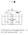
- the reaction mechanism is as follows. On the surface of the zinc present in the aqueous caustic potash solution, there occurs a zinc dissolution reaction represented by the following formula (1). Zn + 4K+ + 4OH ⁇ ⁇ 2K+ + Zn(OH)4 ⁇ + 2K+ + 2e ⁇ (1)
- the hydrous nylon acts as a diaphragm through which K+ migrates, and water present on the iron surface is gradually converted into an aqueous caustic potash solution (K+ + OH ⁇ ), to finally turn the solution highly alkaline.
- K+ + OH ⁇ aqueous caustic potash solution
- the thus formed alkaline solution leaks out through the exhaust port on the bottom plate being the negative electrode terminal, thus causing severe leakage.
- German patent specification DE 2 321 842 shows a cylindrical alkaline battery comprising a positive electrode case of cylindrical form having an opening at one end and accommodating an electricity-generating element comprising a positive electrode, a negative electrode, a separator and an alkaline electrolytic solution, a gasket made of an electric insulating synthetic resin installed within the opening of the positive electrode case, a bottom plate being the negative electrode terminal electrically connected to the negative electrode in the electricity-generating element and installed on the gasket, wherein the opening of the positive electrode case is sealed by bending the open end inwardly and thereby tightening the bottom plate being the negative electrode terminal against the gasket, and a heat-shrinkable resin member covering the outer surface of the positive electrode case.
- This battery does also include a cylindrical paper layer interposed between the positive electrode case and the heat-shrinkable resin member which acts to electrically insulate the positive electrode case should the heat-shrinkable resin member suffer damaged exposing the paper layer.
- the present invention provides an electric insulating film on at least the sealed open end of the positive electrode case on the outer surface of a bent portion of said case adjacent said open end.
- the electric insulating film is constituted by a synthetic resin which differs from a fluid sealing material such as a fat, paraffin or a wax.
- the electric insulating film is an ultra violet curable resin.
- an alkaline battery comprising a positive electrode case of cylindrical form having an opening at one end and accommodating an electricity-generating element comprising a positive electrode, a negative electrode, a separator and an alkaline electrolytic solution, a gasket made of an electric insulating synthetic resin installed within the opening of the positive electrode case, a bottom plate being the negative electrode terminal electrically connected to the negative electrode in the electricity-generating element and installed on the gasket, wherein the opening of the positive electrode case is sealed by bending the opening end inwardly and thereby tightening the bottom plate being the negative electrode terminal against the gasket, and a heat-shrinkable member covering the outer surface of the positive electrode case.
- This battery also includes an insulating washer placed over the open end of the positive electrode case after the case is sealed by bending the open end inwardly.
- a second embodiment of the present invention which provides an insulating ring adjacent a bent opening portion of the positive electrode case on the outside of the heat-shrinkable member.
- Fig. 1 is a view of a cylindrical alkaline battery comprising a first embodiment of the present invention (partial sectional view of the left half);
- Fig. 2 is an enlarged sectional view showing the sealed portion of the battery in Fig. 1;
- Fig. 3 is a partial sectional view of a cylindrical alkaline battery providing a synthetic resin 14;
- Fig. 4 is a partial sectional view of a cylindrical alkaline battery illustrating one way of fixing an insulating ring (16) on bottom plate (6);
- Fig. 5 is a partial sectional view of a cylindrical alkaline battery showing an alternate means for securing an insulating ring;
- Fig. 6 is a drawing showing schematically electrochemical reaction occuring in a battery of the present invention;
- Fig. 7 is an enlarged sectional view showing the sealed portion of a cylindrical alkaline battery;
- Fig. 8 is a drawing showing schematically electrochemical reaction according to another embodiment of the invention.
- Fig. 1 is a metallic battery case functioning as a positive electrode terminal, which contains a positive electrode mix 2 composed mainly of MnO2 and moulded into a cylindrical shape, a bag-shaped separator 4 and a gel-like zinc negative electrode 3.
- Symbol 5 is a negative electrode collector.
- the bottom plate 6 acting as a negative electrode terminal is spot-welded to the end of the negative electrode collector 5 and has an exhaust port 7. This bottom plate 6 is held by caulking the opening 11 of the battery case inwardly and tightening the bottom plate 6 together with a metallic washer 8 provided between the bottom plate 6 and the nylon gasket 10 against a nylon gasket 10.
- a metallic washer 8 provided between the bottom plate 6 and the nylon gasket 10 against a nylon gasket 10.
- the open end 11 and the opening outer surface of the battery case 1 are covered with a ring-shaped electric insulating film 14.
- the electric insulating film 14 may cover the entire outer surface of the battery case 1 from the caulked opening portion to the bottom end of the cylinder.
- a shrink label or shrink tube 15 is applied as a cover.
- the electric insulating film 14 can be formed by, after caulking the opening 11 of the battery case 1 and sealing the opening 11 with the gasket, applying a synthetic resin coating (e.g. phenolic resin coating, epoxy resin coating) to the outer surface of the caulked portion of the battery case 1 and then drying the coating.
- a synthetic resin coating e.g. phenolic resin coating, epoxy resin coating
- the battery of the present invention wherein an electric insulating film 14 is formed on at least the open end and the opening outer surface of the positive electrode case and then a heat-shrinkable member is applied as the cover, not only solves problems of conventional alkaline batteries having only a resin film cover but also can prevent an exterior short circuit and provide the increased reliability. Therefore, the battery has a very high value.
- an electric insulating film by applying and curing, in place of a synthetic resin coating requiring a long drying time, an ultraviolet-curable resin composed mainly of, for example, an epoxy acrylate or an aromatic monoacrylate curable in a short time by ultraviolet irradiation. That is, a synthetic resin coating requires about 30 minutes for drying and formation of film, however, an ultraviolet-curable resin can provide a cured film by ultraviolet irradiation of only about 3 seconds and can give substantially increased work efficiency.
- an insulating ring 16 may be fixed onto the outer surface of the cover film 15 at the caulked portion of the positive electrode case 1 after the cover film 15 consisting of a shrink label or shrink tube has been applied on the entire outer surface of the sealed positive electrode case 1, as shown in Fig. 5.
- the presence of this insulating ring 16 can prevent the peeling or damage of the cover label or cover tube at the battery bottom, can maintain good electric insulation between the positive electrode case 1 and the metallic bottom plate 6 being the negative electrode terminal, and can sufficiently prevent exterior short circuit.
- the insulating ring 16 can be fixed, for example, by ultrasonic-bonding of an insulating ring 16 to the cover film 15 at the caulked portion of the positive electrode case 1 or by adhering an insulating ring 16 to the cover film 15 at the caulked portion of the positive electrode case 1 with an adhesive of solution type, aqueous dispersion type, reactive type or the like.
- the insulating ring 16 can be fixed according to a method as shown in Fig. 4 wherein a lobe 6' is provided at the outer surface of the bottom plate 6 being the negative electrode terminal and an insulating ring 16 is fixed below the lobe 6'.
- the battery of the present invention wherein an insulating ring is fixed onto the outer surface of the cover film at the caulked opening portion of the positive electrode case, solves the problem of conventional alkaline batteries having only a resin film cover, prevents exterior short circuit and provides increased reliability.
- FIG. 2 is an enlarged sectional view of the sealed portion of a cylindrical alkaline battery of the present invention.
- 17 is an insulating film applied onto the upper surface of the metallic washer 8 and characterises the present embodiment.
- the constituting elements of this battery excluding the insulating film 17 are same as those of the battery of Fig. 1.
- This insulating film 17 insulates electrically the metallic washer 8 from the bottom plate 6 being the negative electrode terminal.
- the application of the insulating film 17 onto the upper surface of the metallic washer 8 can prevent leakage even when the battery has been stored under highly humid conditions.
- Fig. 7 is an enlarged sectional view of the sealed opening portion of a cylindrical alkaline battery (drawn in the form of an uncovered battery) as another embodiment (case B) of the present invention.
- 17 is an insulating film applied onto the lower surface and both ends of the metallic washer 8.
- the constituting elements of this battery excluding the insulating film 17 are same as those of the battery of Fig. 1.
- This film 17 cuts off the ionic conduction between the metallic washer 8 and the hydrous nylon gasket 10.
- Fig. 8 which illustrates a schematic case of the electrochemical reaction.
- 17' is an insulating film corresponding to the insulating film 17 of Fig. 7.
- Fig. 8 is an insulating film corresponding to the insulating film 17 of Fig. 7.
- Table 1 shows the results of leakage resistance when alkaline batteries meeting the IEC standard, LR 6 were stored under conditions of 60°C and 90% relative humidity.
- the alkaline batteries of the embodiments (cases A, B) and the above-mentioned other embodiment of the present invention show remarkably improved leakage resistance.
- Table 1 Run No. Storage period, days 7 14 21 28 56 1 (case A) 0 0 0 0 0 2 (case B) 0 0 0 0 3 (other embodiment) 0 0 0 0 0 4 (conventional battery) 0 5 50 90 100
Landscapes
- Chemical & Material Sciences (AREA)
- Chemical Kinetics & Catalysis (AREA)
- Electrochemistry (AREA)
- General Chemical & Material Sciences (AREA)
- Engineering & Computer Science (AREA)
- Manufacturing & Machinery (AREA)
- General Engineering & Computer Science (AREA)
- Mechanical Engineering (AREA)
- Physics & Mathematics (AREA)
- Thermal Sciences (AREA)
- Sealing Battery Cases Or Jackets (AREA)
Claims (10)
- Zylindrische Alkalibatterie, mit
einem positiven Elektrodengehäuse (1) zylindrischer Form, das eine Öffnung (11) an einem Ende hat und ein Elektrizität erzeugendes Element mit einer positiven Elektrode (2), einer negativen Elektrode (3), einer Scheidewand (4) und einer alkalischen Elektrolyt-Lösung beherbergt,
einer aus elektrisch isolierendem synthetischen Harz hergestellten Dichtung (10), die innerhalb der Öffnung (11) des positiven Elektrodengehäuses (1) angebracht ist,
einer den negativen Elektrodenanschluß bildenden Bodenplatte (6), die elektrisch mit der negativen Elektrode in dem Elektrizität erzeugenden Element verbunden ist und die auf der Dichtung angebracht ist,
wobei die Öffnung des positiven Elektrodengehäuses (1) durch Umbiegen des offenen Endes (11) nach Innen und dadurch Befestigen der den negativen Elektrodenanschluß bildenden Bodenplatte (6) gegen die Dichtung (10) abgedichtet ist und
ein wärmeschrumpfbares Harzelement (15) die Mantelfläche des positiven Elektrodengehäuses (1) einfaßt,
wobei die Batterie dadurch gekennzeichnet ist, daß ein von einem synthetischen Harz, das sich von einem Flüssigdichtungsmaterial, wie etwa Fett, Paraffin oder Wachs unterscheidet, gebildeter elektrisch isolierender Film (14) mindestens auf dem offenen Ende des positiven Elektrodengehäuses (1) auf der Außenfläche des umgebogenen Abschnitts des Gehäuses benachbart dem offenen Ende vorgesehen ist. - Zylindrische Alkalibatterie nach Anspruch 1, dadurch gekennzeichnet, daß der elektrisch isolierende Film (14) aus einem ultraviolett-härtbaren Harz hergestellt ist.
- Zylindrische Alkalibatterie nach Anspruch 1, dadurch gekennzeichnet, daß der elektrisch isolierende Film (14) durchgängig auf der Mantelfläche des positiven Elektrodengehäuses (1) von dessen offenem Ende zu dessen anderem Ende ausgebildet ist.
- Zylindrische Alkalibatterie nach Anspruch 1, dadurch gekennzeichnet, daß eine metallische Unterlegscheibe (8) zwischen der synthetischen Harzdichtung (10) und der den negativen Elektrodenanschluß bildenden Bodenplatte (6) vorgesehen ist.
- Zylindrische Alkalibatterie, mit
einem positiven Elektrodengehäuse (1) zylindrischer Form, das eine Öffnung (11) an einem Ende hat und ein Elektrizität erzeugendes Element mit einer positiven Elektrode (2), einer negativen Elektrode (3), einer Scheidewand (4) und einer alkalischen Elektrolyt-Lösung beherbergt,
einer aus elektrisch isolierendem synthetischen Harz hergestellten Dichtung (10), die innerhalb der Öffnung (11) des positiven Elektrodengehäuses (1) angebracht ist,
einer den negativen Elektrodenanschluß bildenden Bodenplatte (6), die elektrisch mit der negativen Elektrode in dem Elektrizität erzeugenden Element verbunden ist und die auf der Dichtung (10) angebracht ist,
wobei die Öffnung des positiven Elektrodengehäuses (1) durch Umbiegen des öffnenden Endes (11) nach Innen und dadurch Befestigen der den negativen Elektrodenanschluß bildenden Bodenplatte (6) gegen die Dichtung (10) abgedichtet ist und
ein wärmeschrumpfbares Element (15) die Mantelfläche des positiven Elektrodengehäuses (1) einfaßt,
wobei die Batterie dadurch gekennzeichnet ist, daß ein Isolierring (16) benachbart einem gebogenen öffnenden Abschnitt des positiven Elektrodengehäuses (1) auf der Mantelfläche des wärmeschrumpfbaren Harzelementes (15) vorgesehen ist. - Zylindrische Alkalibatterie nach Anspruch 5, dadurch gekennzeichnet, daß eine metallische Unterlegscheibe (8) zwischen der synthetischen Harzdichtung (10) und der den negativen Elektrodenanschluß bildenden Bodenplatte (6) vorgesehen ist.
- Zylindrische Alkalibatterie nach Anspruch 5, dadurch gekennzeichnet, daß der Isolierring (16) außen bezüglich dem wärmeschrumpfbaren Harzelement vorgesehen und daran angeheftet ist.
- Zylindrische Alkalibatterie nach Anspruch 5, dadurch gekennzeichnet, daß der Isolierring (16) außen bezüglich des wärmeschrumpfbaren Harzelementes vorgesehen ist und mittels einer Nase (6') auf der Bodenplatte (6) benachbart einem gebogenen öffnenden Abschnitt des positiven Elektrodengehäuses in Position befestigt ist.
- Zylindrische Alkalibatterie nach Anspruch 5, dadurch gekennzeichnet, daß der Isolierring (16) außen bezüglich des wärmeschrumpfbaren Harzelementes (15) vorgesehen und an der Mantelfläche des positiven Elektrodengehäuses (1) in Form einer bodenlosen Manschette befestigt ist.
- Zylindrische Alkalibatterie nach Anspruch 5, dadurch gekennzeichnet, daß der Isolierring (16) außen bezüglich des wärmeschrumpfbaren Harzelementes vorgesehen und daran mittels Ultraschallverbindens angeheftet ist.
Priority Applications (1)
| Application Number | Priority Date | Filing Date | Title |
|---|---|---|---|
| EP91116087A EP0466213B1 (de) | 1987-08-28 | 1988-08-26 | Zylindrische alkalische Batterien |
Applications Claiming Priority (6)
| Application Number | Priority Date | Filing Date | Title |
|---|---|---|---|
| JP62215651A JPS6459756A (en) | 1987-08-28 | 1987-08-28 | Alkaline dry battery |
| JP215651/87 | 1987-08-28 | ||
| JP62331994A JPH01175163A (ja) | 1987-12-28 | 1987-12-28 | アルカリ乾電池 |
| JP331994/87 | 1987-12-28 | ||
| JP63113909A JP2769158B2 (ja) | 1988-05-11 | 1988-05-11 | アルカリ乾電池 |
| JP113909/88 | 1988-05-11 |
Related Child Applications (1)
| Application Number | Title | Priority Date | Filing Date |
|---|---|---|---|
| EP91116087.7 Division-Into | 1988-08-26 |
Publications (3)
| Publication Number | Publication Date |
|---|---|
| EP0309101A2 EP0309101A2 (de) | 1989-03-29 |
| EP0309101A3 EP0309101A3 (en) | 1989-11-15 |
| EP0309101B1 true EP0309101B1 (de) | 1993-02-24 |
Family
ID=27312616
Family Applications (2)
| Application Number | Title | Priority Date | Filing Date |
|---|---|---|---|
| EP88307958A Expired - Lifetime EP0309101B1 (de) | 1987-08-28 | 1988-08-26 | Zylindrische alkalische Batterien |
| EP91116087A Expired - Lifetime EP0466213B1 (de) | 1987-08-28 | 1988-08-26 | Zylindrische alkalische Batterien |
Family Applications After (1)
| Application Number | Title | Priority Date | Filing Date |
|---|---|---|---|
| EP91116087A Expired - Lifetime EP0466213B1 (de) | 1987-08-28 | 1988-08-26 | Zylindrische alkalische Batterien |
Country Status (6)
| Country | Link |
|---|---|
| US (1) | US4869978A (de) |
| EP (2) | EP0309101B1 (de) |
| KR (1) | KR920004316B1 (de) |
| AU (1) | AU594249B2 (de) |
| CA (1) | CA1305753C (de) |
| DE (2) | DE3878617T2 (de) |
Families Citing this family (17)
| Publication number | Priority date | Publication date | Assignee | Title |
|---|---|---|---|---|
| US5051323A (en) * | 1990-04-13 | 1991-09-24 | Eveready Battery Company, Inc. | Rollback inner cover |
| JP2543325Y2 (ja) * | 1991-01-14 | 1997-08-06 | ソニー株式会社 | 電 池 |
| US5173371A (en) * | 1991-03-11 | 1992-12-22 | Eveready Battery Company, Inc. | Battery to prevent cell reversal |
| FR2680132A1 (fr) * | 1991-08-05 | 1993-02-12 | Rotanotice Sa | Procede pour obtenir une etiquette de protection et de decoration autour du corps cylindrique d'une pile electrique. |
| US5324332A (en) * | 1992-10-30 | 1994-06-28 | Rayovac Corporation | Alkaline manganese dioxide cells |
| DE19643011A1 (de) * | 1996-10-18 | 1998-04-23 | Varta Batterie | Direkt berdrucktes galvanisches Element |
| JP3612931B2 (ja) * | 1996-10-31 | 2005-01-26 | 松下電器産業株式会社 | 円筒型アルカリ電池 |
| US5985479A (en) * | 1997-11-14 | 1999-11-16 | Eveready Battery Company, Inc. | Electrochemical cell having current path interrupter |
| TWI275194B (en) * | 2004-10-08 | 2007-03-01 | Lg Chemical Ltd | Secondary battery having an improved safety |
| US8053106B1 (en) * | 2005-12-01 | 2011-11-08 | Quallion Llc | Battery with improved insulator |
| KR100795682B1 (ko) * | 2006-02-27 | 2008-01-21 | 삼성에스디아이 주식회사 | 이차전지 및 그 제조방법 |
| US20090029238A1 (en) * | 2007-07-25 | 2009-01-29 | Schubert Mark A | Electrochemical cell having polymeric moisture barrier |
| JP2010003681A (ja) * | 2008-05-19 | 2010-01-07 | Panasonic Corp | 蓄電装置 |
| AT508742B1 (de) * | 2009-09-10 | 2011-07-15 | Norman Neuhold | Einsatz für ein akkumulatorteil |
| CN103531729B (zh) * | 2013-10-31 | 2015-10-14 | 无锡市金杨新型电源有限公司 | 电池壳生产用切口机构 |
| EP4097786A1 (de) | 2020-05-22 | 2022-12-07 | Duracell U.S. Operations, Inc. | Dichtungsanordnung für eine batteriezelle |
| KR102868036B1 (ko) * | 2020-06-25 | 2025-10-01 | 삼성에스디아이 주식회사 | 이차 전지 |
Family Cites Families (9)
| Publication number | Priority date | Publication date | Assignee | Title |
|---|---|---|---|---|
| US3694267A (en) * | 1970-11-23 | 1972-09-26 | Mallory & Co Inc P R | Leakproof closure seal for battery |
| FR2123618A5 (de) * | 1971-01-25 | 1972-09-15 | Accumulateurs Fixes | |
| FR2148841A5 (de) * | 1971-08-05 | 1973-03-23 | Sev Marchal | |
| US3897270A (en) * | 1973-01-30 | 1975-07-29 | Power Conversion Inc | Battery construction with improved terminal attaching structure |
| DE2321842C3 (de) * | 1973-04-30 | 1980-09-11 | Fuji Electrochemical Co. Ltd., Tokio | Elektrochemische Zelle |
| JPS56138860A (en) * | 1980-04-01 | 1981-10-29 | Hitachi Maxell Ltd | Cylindrical alkaline battery |
| US4567118A (en) * | 1983-07-11 | 1986-01-28 | Duracell Inc. | Cell vent |
| US4537841A (en) * | 1983-11-04 | 1985-08-27 | Duracell Inc. | Metal-supported seals for galvanic cells |
| US4606983A (en) * | 1985-02-25 | 1986-08-19 | Duracell Inc. | Anchored terminal conductor |
-
1988
- 1988-08-12 KR KR1019880010294A patent/KR920004316B1/ko not_active Expired - Lifetime
- 1988-08-22 US US07/234,603 patent/US4869978A/en not_active Expired - Lifetime
- 1988-08-23 AU AU21454/88A patent/AU594249B2/en not_active Expired
- 1988-08-25 CA CA000575720A patent/CA1305753C/en not_active Expired - Lifetime
- 1988-08-26 EP EP88307958A patent/EP0309101B1/de not_active Expired - Lifetime
- 1988-08-26 DE DE8888307958T patent/DE3878617T2/de not_active Expired - Lifetime
- 1988-08-26 EP EP91116087A patent/EP0466213B1/de not_active Expired - Lifetime
- 1988-08-26 DE DE3854899T patent/DE3854899T2/de not_active Expired - Lifetime
Non-Patent Citations (2)
| Title |
|---|
| PATENT ABSTRACT OF JAPAN, vol. 7, no. 4(E-151)(1149), January 8, 1983 & JP-A-57 163 960 (HITACHI MAXELL K.K.) 08-10-1982 * |
| PATENT ABSTRACT OF JAPAN, vol. 9, no. 65 (E304)(1788), March 26, 1985 & JP-A-59 203 363 (FUJI DENKI KAGAKU K.K.) 17-11-1984 * |
Also Published As
| Publication number | Publication date |
|---|---|
| DE3878617T2 (de) | 1993-06-09 |
| KR920004316B1 (ko) | 1992-06-01 |
| DE3878617D1 (de) | 1993-04-01 |
| DE3854899D1 (de) | 1996-02-22 |
| EP0309101A3 (en) | 1989-11-15 |
| EP0466213A3 (en) | 1992-03-04 |
| AU2145488A (en) | 1989-05-25 |
| EP0309101A2 (de) | 1989-03-29 |
| AU594249B2 (en) | 1990-03-01 |
| KR890004460A (ko) | 1989-04-22 |
| DE3854899T2 (de) | 1996-09-12 |
| EP0466213B1 (de) | 1996-01-10 |
| EP0466213A2 (de) | 1992-01-15 |
| US4869978A (en) | 1989-09-26 |
| CA1305753C (en) | 1992-07-28 |
Similar Documents
| Publication | Publication Date | Title |
|---|---|---|
| EP0466213B1 (de) | Zylindrische alkalische Batterien | |
| US4567121A (en) | Insulating seal for electrochemical cells | |
| WO1994010712A1 (en) | Battery packaging and interconnection scheme | |
| US3922178A (en) | Alkaline battery seal and protective coating comprising a fatty acidamide | |
| US3081367A (en) | Electrode assembly for sealed rechargeable alkaline battery cells | |
| KR101006883B1 (ko) | 전해액 흡입성 와셔를 포함하고 있는 전지 | |
| JPS63150854A (ja) | 電池回路電流断続器 | |
| US4258108A (en) | Leak-proofing of button cells | |
| US4087595A (en) | Multi-cell battery and method of making | |
| EP0081339A2 (de) | Abdichten von elektrochemischen Zellen | |
| KR100369070B1 (ko) | 전지의 외장재 | |
| US3694267A (en) | Leakproof closure seal for battery | |
| JP2001332226A (ja) | アルカリ乾電池 | |
| KR100551397B1 (ko) | 파우치형 리튬 이차전지 | |
| KR100551395B1 (ko) | 파우치형 리튬 이차 전지 제조 방법 | |
| GB2261544A (en) | Metal oxide-hydrogen battery having rectangular modules in a cylindrical pressure vessel | |
| JP3218820B2 (ja) | 紙外装体を備えた蓄電池 | |
| US3634142A (en) | Magnesium dry battery with anode contact protection | |
| JPH04248249A (ja) | コイン型有機電解液セルとその製造方法 | |
| JPS63193461A (ja) | アルカリ乾電池 | |
| KR940006078Y1 (ko) | 전기 이중층 콘덴서 | |
| JPS6344947Y2 (de) | ||
| JP2769158B2 (ja) | アルカリ乾電池 | |
| CN121394709A (zh) | 一种圆柱电池及用电装置 | |
| US2038060A (en) | Electric battery |
Legal Events
| Date | Code | Title | Description |
|---|---|---|---|
| PUAI | Public reference made under article 153(3) epc to a published international application that has entered the european phase |
Free format text: ORIGINAL CODE: 0009012 |
|
| AK | Designated contracting states |
Kind code of ref document: A2 Designated state(s): BE CH DE FR GB IT LI NL |
|
| 17P | Request for examination filed |
Effective date: 19890413 |
|
| PUAL | Search report despatched |
Free format text: ORIGINAL CODE: 0009013 |
|
| AK | Designated contracting states |
Kind code of ref document: A3 Designated state(s): BE CH DE FR GB IT LI NL |
|
| 17Q | First examination report despatched |
Effective date: 19910321 |
|
| GRAA | (expected) grant |
Free format text: ORIGINAL CODE: 0009210 |
|
| ITF | It: translation for a ep patent filed | ||
| AK | Designated contracting states |
Kind code of ref document: B1 Designated state(s): BE CH DE FR GB IT LI NL |
|
| XX | Miscellaneous (additional remarks) |
Free format text: TEILANMELDUNG 91116087.7 EINGEREICHT AM 26/08/88. |
|
| REF | Corresponds to: |
Ref document number: 3878617 Country of ref document: DE Date of ref document: 19930401 |
|
| ET | Fr: translation filed | ||
| ITTA | It: last paid annual fee | ||
| PLBE | No opposition filed within time limit |
Free format text: ORIGINAL CODE: 0009261 |
|
| STAA | Information on the status of an ep patent application or granted ep patent |
Free format text: STATUS: NO OPPOSITION FILED WITHIN TIME LIMIT |
|
| 26N | No opposition filed | ||
| REG | Reference to a national code |
Ref country code: GB Ref legal event code: IF02 |
|
| PGFP | Annual fee paid to national office [announced via postgrant information from national office to epo] |
Ref country code: NL Payment date: 20060815 Year of fee payment: 19 |
|
| PGFP | Annual fee paid to national office [announced via postgrant information from national office to epo] |
Ref country code: DE Payment date: 20070823 Year of fee payment: 20 |
|
| PGFP | Annual fee paid to national office [announced via postgrant information from national office to epo] |
Ref country code: CH Payment date: 20070830 Year of fee payment: 20 |
|
| PGFP | Annual fee paid to national office [announced via postgrant information from national office to epo] |
Ref country code: GB Payment date: 20070822 Year of fee payment: 20 |
|
| PGFP | Annual fee paid to national office [announced via postgrant information from national office to epo] |
Ref country code: IT Payment date: 20070828 Year of fee payment: 20 |
|
| PGFP | Annual fee paid to national office [announced via postgrant information from national office to epo] |
Ref country code: BE Payment date: 20071012 Year of fee payment: 20 |
|
| PG25 | Lapsed in a contracting state [announced via postgrant information from national office to epo] |
Ref country code: NL Free format text: LAPSE BECAUSE OF NON-PAYMENT OF DUE FEES Effective date: 20080301 |
|
| PGFP | Annual fee paid to national office [announced via postgrant information from national office to epo] |
Ref country code: FR Payment date: 20070808 Year of fee payment: 20 |
|
| NLV4 | Nl: lapsed or anulled due to non-payment of the annual fee |
Effective date: 20080301 |
|
| REG | Reference to a national code |
Ref country code: CH Ref legal event code: PFA Owner name: MATSUSHITA ELECTRIC INDUSTRIAL CO., LTD Free format text: MATSUSHITA ELECTRIC INDUSTRIAL CO., LTD#1006, OAZA KADOMA#KADOMA-SHI/OSAKA-FU (JP) -TRANSFER TO- MATSUSHITA ELECTRIC INDUSTRIAL CO., LTD#1006, OAZA KADOMA#KADOMA-SHI/OSAKA-FU (JP) |
|
| BE20 | Be: patent expired |
Owner name: *MATSUSHITA ELECTRIC INDUSTRIAL CO. LTD Effective date: 20080826 |
|
| REG | Reference to a national code |
Ref country code: CH Ref legal event code: PL |
|
| REG | Reference to a national code |
Ref country code: GB Ref legal event code: PE20 Expiry date: 20080825 |
|
| PG25 | Lapsed in a contracting state [announced via postgrant information from national office to epo] |
Ref country code: GB Free format text: LAPSE BECAUSE OF EXPIRATION OF PROTECTION Effective date: 20080825 |