EP0308686B1 - Abtastprisma - Google Patents
Abtastprisma Download PDFInfo
- Publication number
- EP0308686B1 EP0308686B1 EP88114027A EP88114027A EP0308686B1 EP 0308686 B1 EP0308686 B1 EP 0308686B1 EP 88114027 A EP88114027 A EP 88114027A EP 88114027 A EP88114027 A EP 88114027A EP 0308686 B1 EP0308686 B1 EP 0308686B1
- Authority
- EP
- European Patent Office
- Prior art keywords
- prism
- scanning
- axis
- reflection
- top surface
- Prior art date
- Legal status (The legal status is an assumption and is not a legal conclusion. Google has not performed a legal analysis and makes no representation as to the accuracy of the status listed.)
- Expired - Lifetime
Links
- 238000000034 method Methods 0.000 description 2
- 238000003384 imaging method Methods 0.000 description 1
- 238000011835 investigation Methods 0.000 description 1
- 238000005259 measurement Methods 0.000 description 1
- 238000012821 model calculation Methods 0.000 description 1
- 230000003287 optical effect Effects 0.000 description 1
- 239000004065 semiconductor Substances 0.000 description 1
Images


Classifications
-
- G—PHYSICS
- G02—OPTICS
- G02B—OPTICAL ELEMENTS, SYSTEMS OR APPARATUS
- G02B26/00—Optical devices or arrangements for the control of light using movable or deformable optical elements
- G02B26/08—Optical devices or arrangements for the control of light using movable or deformable optical elements for controlling the direction of light
- G02B26/10—Scanning systems
-
- G—PHYSICS
- G02—OPTICS
- G02B—OPTICAL ELEMENTS, SYSTEMS OR APPARATUS
- G02B5/00—Optical elements other than lenses
- G02B5/04—Prisms
Definitions
- German patent application P 35 17 671.7 this method is extended and applied to optical-mechanical scanners.
- the reflective surfaces (5) and (6) are changed.
- these reflection surfaces (5) and (6) are perpendicular to one another and their intersection lies in the axis of rotation (7) of the scanning prism.
- these reflection surfaces are inclined at a certain angle ⁇ not equal to zero and 90 ° against the axis of rotation (7) of the scanning prism.
- a two-part prism With a two-part prism, the arrangement shown in Fig. 3 is created.
- the inclination ⁇ of the reflection surface (10) produces two intersecting, slightly curved, hyperbola-like scanning tracks (A1), (A2) when the prism is rotated fully on the object plane.
- the offset ⁇ s arises between the two scan tracks.
- the narrow triangular surfaces (hatched) between the intersection lines of the reflection surfaces with the prism surfaces and the roof edges of the scanning prism must be covered, since they would otherwise direct unwanted secondary light into the beam path.
Landscapes
- Physics & Mathematics (AREA)
- General Physics & Mathematics (AREA)
- Optics & Photonics (AREA)
- Navigation (AREA)
- Measurement Of Optical Distance (AREA)
- Mechanical Optical Scanning Systems (AREA)
- Optical Elements Other Than Lenses (AREA)
- Facsimile Scanning Arrangements (AREA)
Description
- Für die Bestimmung der Orientierungsparameter eines von einem Flugkörper oder einem anderen bewegten Objekt getragenen Dreizeilen-Abtaster besteht der Bedarf nach Erzeugung von Abtastspuren, die einen gewissen Winkel zum Flugweg bilden. In den deutschen Patentschriften DE 29 40 871 C 2, DE 30 43 577 C 2 und DE 32 19 032 C 2 werden Vorrichtungen und Verfahren beschrieben, die es ermöglichen, mit optisch-elektronischen Abtastern unter Benützung von drei Halbleitersensorzeilen die Orientierungsparameter der Kamera und das Geländemodell des abgetasteten Geländes zu bestimmen.
- In der deutschen Patentanmeldung P 35 17 671.7 wird dieses Verfahren auf optisch-mechanische Abtaster ausgedehnt und angewendet.
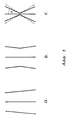
- In der o.g. Patentschrift 30 43 577 und darauf aufbauenden Untersuchungen und Veröffentlichungen (z.B. Hofmann, O.: Dynamische Photogrammetrie, Heft 3, Bildmessung und Luftbildwesen, 1986) wird gezeigt, daß die winklige Anordnung der beiden äußeren, in der Bildebene eines Objektivs angeordneten Sensorzeilen und die von ihnen erzeugten winkligen Abtastspuren eine größere Stabilität und Genauigkeit der Modellberechnung (Orientierungsparameter und Geländepunkte) erreichen als parallele Anordnungen (Abb. 1). In Abb. 1a verlaufen die äußeren Sensorzeilen bzw. ihre Spuren im Gelände trapezförmig, in der Abb. 1b schwach pfeilförmig. Im extremen Fall des Tieffluges hat es sich aus Genauigkeits- und Stabilitätsgründen als günstig erwiesen, diese pfeilförmigen Abtastspuren der äußeren Sensoren so weit zu verändern, daß die Pfeilspitzen etwa auf die Mitte der mittleren Sensorzeile bzw. Abtastspuren weisen und die Pfielwinkel auf etwa 30° vergrößert werden (Abb. 1c). Es ist nicht erforderlich, daß die durch die Sensoren erzeugten Abtastspuren exakt gerade verlaufen, sie können z.B. schwach hyperbel-ähnlich gekrümmt sein, wie das die punktierten Linien in Abb. 1c andeuten. In der o.g. Patentanmeldung P 35 17 671.7 werden diese äußeren Abtastspuren durch Drehspiegel mit zur Drehachse geneigten Spiegelnormalen erzeugt. Dabei entstehen zwangsläufig hyperbel-ähnliche Abtastspuren.
- Die Abtastung mit Drehspiegeln führt aber vor allem bei großen Bildwinkeln bis 180° zu unhandlich großen Spiegelflächen, Gerätedimensionen und hohen Rotationsmomenten. Nachfolgend wird beschrieben, wie mit einem Drehprisma besonderer Ausbildung diese Nachteile umgangen werden können.
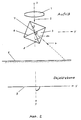
- Es ist bekannt, daß mit einem zwei- oder vierteiligen Abtastprisma (siehe deutsche Patentanmeldung P 21 21 918.1, Abtastprisma), das vor einem Objektiv (1) angeordnet ist, bei einer Umdrehung des Prismas (3) um die Achse (7) zwei bzw. vier Abtastungen erzeugt werden, je nachdem ob das Prisma zwei- oder vierteilig ausgebildet ist (Abb. 2). Dabei wird das unter dem Winkel α auf das Prisma treffende Strahlenbündel (2) jeweils um den doppelten Betrag 2α in Strahlrichtung (4) abgelenkt. Die auf der Objektebene (8) erzeugten Abtastspuren (9) des Strahlenbündels (4) verlaufen rechtwinklig zur Rotationsachse (7) des Abtastprismas (x-Richtung des Abtasters), wobei die Objektebene (8) parallel zur Rotationsachse (7) des Abtastprismas und normal zur optischen Achse (2) des Objektivs (1) liegt. Um Abtastspuren zu erzeugen, die unter einem bestimmten Winkel γ zur X-Achse des Abtasters bzw. zur Flugrichtung verlaufen (siehe Abb. 1c, 3, 4), werden die Reflexionsflächen (5) und (6) verändert. Bei der bisher bekannten Ausführungsform stehen diese Reflexionsflächen (5) und (6) rechtwinklig aufeinander und ihre Schnittlinie liegt in der Rotationsachse (7) des Abtastprismas.
- Erfindungsgemäß werden diese Reflexionsflächen unter einem bestimmten Winkel β ungleich Null und 90° gegen die Drehachse (7) des Abtastprismas geneigt.
- Bei einem zweiteiligen Prisma entsteht damit die in Abb. 3 dargestellte Anordnung. Die Neigung β der Reflexionsfläche (10) erzeugt bei einer vollen Umdrehung des Prismas auf der Objektebene zwei sich kreuzende, schwach gekrümmte, hyperbelähnliche Abtastspuren (A1), (A2). Bei einer gleichzeitigen Vorwärtsbewegung des Abtasters in X-Richtung entsteht zwischen beiden Abtastspuren der Versatz Δs.
- Die beiden Reflexionsflächen schneiden sich rechtwinklig, aber ihre Schnittlinie (12) fällt nicht mehr mit der Prismendrehachse (7) zusammen. Eine volle Rotation dieses vierteiligen Abtastprismas erzeugt vier sich kreuzende Abtastspuren (A1), (A2), (A3), (A4).
- Die schmalen dreieckförmigen Flächen (schraffiert) zwischen den Schnittlinien der Reflexionsflächen mit den Prismenflächen und den Dachkanten des Abtastprismas müssen abgedeckt sein, da sie sonst unerwünschtes Nebenlicht in den Strahlengang lenken.
Claims (3)
- Gerades Abtastprisma mit quadratischer Grund- und Deckfläche, und einer im Inneren des Prismas befindlichen ebenen Reflexionsfläche (10), die die Grundfläche und die Deckfläche schneidet, und die durch das Zentrum des Prismas verläuft, dadurch gekennzeichnet, daß die Reflexionsfläche gegenüber der durch die Grundfläche und Deckfläche laufenden Symmetrieachse (7) um einen vorgegebenen Winkel (β) ungleich Null und 90° geneigt ist und daß sie zwei gegenüberliegende, zur Symmetrieachse parallele Dachkanten des Prismas in der Mitte schneidet.
- Abtastprisma nach Anspruch 1, dadurch gekennzeichnet, daß eine zweite Reflexionsfläche (11) vorhanden ist, die durch das Zentrum des Prismas verläuft und deren Schnittlinien mit der Grundfläche und der Deckfläche rechtwinklig zu den Schnittlinien der ersten Reflexionsfläche (10) mit der Grundfläche und der Deckfläche verlaufen, und daß diese zweite Reflexionsfläche ebenfalls um den Winkel (β) gegenüber der Symmetrieachse (7) geneigt ist.
- Abtastprisma nach Anspruch 1 und 2, dadurch gekennzeichnet, daß die Dreiecksflächen zwischen den Dachkanten des Prismas und den Schnittlinien der Reflexionsflächen mit den Prismenflächen zur Unterdrückung von Nebenlicht abgedeckt werden.
Applications Claiming Priority (2)
| Application Number | Priority Date | Filing Date | Title |
|---|---|---|---|
| DE19873732068 DE3732068A1 (de) | 1987-09-23 | 1987-09-23 | Abtastprisma |
| DE3732068 | 1987-09-23 |
Publications (2)
| Publication Number | Publication Date |
|---|---|
| EP0308686A1 EP0308686A1 (de) | 1989-03-29 |
| EP0308686B1 true EP0308686B1 (de) | 1993-03-10 |
Family
ID=6336698
Family Applications (1)
| Application Number | Title | Priority Date | Filing Date |
|---|---|---|---|
| EP88114027A Expired - Lifetime EP0308686B1 (de) | 1987-09-23 | 1988-08-27 | Abtastprisma |
Country Status (3)
| Country | Link |
|---|---|
| US (1) | US4940312A (de) |
| EP (1) | EP0308686B1 (de) |
| DE (2) | DE3732068A1 (de) |
Families Citing this family (4)
| Publication number | Priority date | Publication date | Assignee | Title |
|---|---|---|---|---|
| DE69125125T2 (de) * | 1990-12-27 | 1997-08-21 | Philips Electronics Nv | Farbbildanzeigevorrichtung und Schaltung zur Ansteuerung vom Lichtventil einer solcher Vorrichtung |
| US5410370A (en) * | 1990-12-27 | 1995-04-25 | North American Philips Corporation | Single panel color projection video display improved scanning |
| JP2585885B2 (ja) * | 1991-05-08 | 1997-02-26 | ローム株式会社 | 画像認識装置 |
| CN105955281B (zh) * | 2016-04-27 | 2018-08-28 | 西安应用光学研究所 | 一种应用于机载红外辅助导航的Risley棱镜系统控制方法 |
Family Cites Families (9)
| Publication number | Priority date | Publication date | Assignee | Title |
|---|---|---|---|---|
| US3320019A (en) * | 1963-12-30 | 1967-05-16 | Gen Electric | Scanning prism utilizing four roof prism components |
| DE2105079A1 (de) * | 1970-02-05 | 1972-08-31 | Emi Ltd | Optische Abtastanordnung |
| DE2121918A1 (de) * | 1971-05-04 | 1972-11-16 | Messerschmitt-Bölkow-Blohm GmbH, 8000 München | Abtastprisma |
| DE2833808C3 (de) * | 1978-08-02 | 1982-04-01 | Deutsche Forschungs- und Versuchsanstalt für Luft- und Raumfahrt e.V., 5000 Köln | Stereo-Zeilenabtaster |
| US4204122A (en) * | 1978-08-14 | 1980-05-20 | Electro Optik GmbH & Co. KG | Method of and device for scanning pictures |
| DE2940871C2 (de) * | 1979-10-09 | 1983-11-10 | Messerschmitt-Bölkow-Blohm GmbH, 8012 Ottobrunn | Photogrammetrisches Verfahren für Fluggeräte und Raumflugkörper zur digitalen Geländedarstellung |
| DE3043577C2 (de) * | 1980-11-19 | 1983-11-17 | Messerschmitt-Bölkow-Blohm GmbH, 8000 München | Photogrammetrische Vorrichtung für Fluggeräte und Raumflugkörper zur digitalen Geländedarstellung |
| DE3219032C3 (de) * | 1982-05-19 | 1988-07-07 | Messerschmitt-Bölkow-Blohm GmbH, 8000 München | Stereophotogrammetrisches aufnahme- und auswerteverfahren |
| DE3517671A1 (de) * | 1985-05-15 | 1986-11-20 | Messerschmitt-Bölkow-Blohm GmbH, 8012 Ottobrunn | Vorrichtung zum bildpunktweisen erfassen der oberflaechengestalt eines entfernten objektes |
-
1987
- 1987-09-23 DE DE19873732068 patent/DE3732068A1/de not_active Withdrawn
-
1988
- 1988-08-27 DE DE8888114027T patent/DE3879060D1/de not_active Expired - Fee Related
- 1988-08-27 EP EP88114027A patent/EP0308686B1/de not_active Expired - Lifetime
- 1988-09-23 US US07/249,355 patent/US4940312A/en not_active Expired - Lifetime
Also Published As
| Publication number | Publication date |
|---|---|
| EP0308686A1 (de) | 1989-03-29 |
| US4940312A (en) | 1990-07-10 |
| DE3732068A1 (de) | 1989-04-06 |
| DE3879060D1 (de) | 1993-04-15 |
Similar Documents
| Publication | Publication Date | Title |
|---|---|---|
| DE102004050682B4 (de) | Einrichtung zur Aufnahme eines Objektraumes | |
| DE2501015C2 (de) | Beruehrungsfreies Dickenmessverfahren | |
| DE2833808C3 (de) | Stereo-Zeilenabtaster | |
| DE1548707B2 (de) | Fotoelektrischer schrittgeber | |
| EP2619526B1 (de) | Autokollimationsfernrohr mit kamera | |
| KR900015396A (ko) | 레이저 빔 편향 장치 | |
| DE3878021T2 (de) | Synchrone optische abtastvorrichtung. | |
| DE102004033928B4 (de) | Abtastvorrichtung zum Vermessen der Konturen eines Objektes | |
| DE69932668T2 (de) | Lasersystem | |
| DE2251913A1 (de) | Mehrzeilen-abtastvorrichtung mit einem polygonalen drehkoerper | |
| DE2800473C2 (de) | Optische Abtasteinrichtung | |
| DE3939905A1 (de) | Winkelgeber | |
| DE19737170C2 (de) | Optisches Kaskade-Abtastsystem | |
| DE3307484C2 (de) | Optisch-mechanischer Abtaster | |
| EP0308686A1 (de) | Abtastprisma | |
| DE10216405A1 (de) | Vorrichtung zum Erzeugen eines dreidimensionalen Umgebungsbildes | |
| DE69501072T2 (de) | Tragbares Gerät zum Messen der Rückstreuung von Licht | |
| DE3707023A1 (de) | Vorrichtung zum ablenken eines strahlenbuendels | |
| DE69512487T2 (de) | Sensoreinrichtung zur Erderfassung für einen Satelliten oder Ähnliches mit einer pyroelektrischen Detektormatrix | |
| DE3517671A1 (de) | Vorrichtung zum bildpunktweisen erfassen der oberflaechengestalt eines entfernten objektes | |
| DE10259667B4 (de) | Verfahren zur Vergrößerung des Bildfeldes einer Focal-Plane-Array-Kamera | |
| DE3702691A1 (de) | Beruehrungsloser abstandssensor | |
| DE1812224A1 (de) | Vorrichtung zur Verbesserung der Zielgenauigkeit eines optischen Ziel- und Ortungsgeraets | |
| DE2226371A1 (de) | Passives ueberwachungsverfahren und anordnung zu dessen realisierung | |
| DE3543648A1 (de) | Verfahren und einrichtung zur systematischen ablenkung von licht |
Legal Events
| Date | Code | Title | Description |
|---|---|---|---|
| PUAI | Public reference made under article 153(3) epc to a published international application that has entered the european phase |
Free format text: ORIGINAL CODE: 0009012 |
|
| AK | Designated contracting states |
Kind code of ref document: A1 Designated state(s): CH DE FR GB IT LI |
|
| 17P | Request for examination filed |
Effective date: 19890817 |
|
| 17Q | First examination report despatched |
Effective date: 19910809 |
|
| RAP1 | Party data changed (applicant data changed or rights of an application transferred) |
Owner name: DEUTSCHE AEROSPACE AKTIENGESELLSCHAFT |
|
| GRAA | (expected) grant |
Free format text: ORIGINAL CODE: 0009210 |
|
| AK | Designated contracting states |
Kind code of ref document: B1 Designated state(s): CH DE FR GB IT LI |
|
| REF | Corresponds to: |
Ref document number: 3879060 Country of ref document: DE Date of ref document: 19930415 |
|
| GBT | Gb: translation of ep patent filed (gb section 77(6)(a)/1977) |
Effective date: 19930427 |
|
| ITF | It: translation for a ep patent filed | ||
| ET | Fr: translation filed | ||
| PLBE | No opposition filed within time limit |
Free format text: ORIGINAL CODE: 0009261 |
|
| STAA | Information on the status of an ep patent application or granted ep patent |
Free format text: STATUS: NO OPPOSITION FILED WITHIN TIME LIMIT |
|
| 26N | No opposition filed | ||
| REG | Reference to a national code |
Ref country code: GB Ref legal event code: 732E |
|
| REG | Reference to a national code |
Ref country code: CH Ref legal event code: PUE Owner name: DAIMLER-BENZ AEROSPACE AKTIENGESELLSCHAFT -DANN AN Ref country code: CH Ref legal event code: PFA Free format text: DEUTSCHE AEROSPACE AKTIENGESELLSCHAFT TRANSFER- DAIMLER-BENZ AEROSPACE AKTIENGESELLSCHAFT |
|
| REG | Reference to a national code |
Ref country code: FR Ref legal event code: CD |
|
| REG | Reference to a national code |
Ref country code: FR Ref legal event code: TP |
|
| PGFP | Annual fee paid to national office [announced via postgrant information from national office to epo] |
Ref country code: GB Payment date: 20010713 Year of fee payment: 14 |
|
| PGFP | Annual fee paid to national office [announced via postgrant information from national office to epo] |
Ref country code: CH Payment date: 20010716 Year of fee payment: 14 |
|
| PGFP | Annual fee paid to national office [announced via postgrant information from national office to epo] |
Ref country code: FR Payment date: 20010801 Year of fee payment: 14 Ref country code: DE Payment date: 20010801 Year of fee payment: 14 |
|
| REG | Reference to a national code |
Ref country code: GB Ref legal event code: IF02 |
|
| PG25 | Lapsed in a contracting state [announced via postgrant information from national office to epo] |
Ref country code: GB Free format text: LAPSE BECAUSE OF NON-PAYMENT OF DUE FEES Effective date: 20020827 |
|
| PG25 | Lapsed in a contracting state [announced via postgrant information from national office to epo] |
Ref country code: LI Free format text: LAPSE BECAUSE OF NON-PAYMENT OF DUE FEES Effective date: 20020831 Ref country code: CH Free format text: LAPSE BECAUSE OF NON-PAYMENT OF DUE FEES Effective date: 20020831 |
|
| PG25 | Lapsed in a contracting state [announced via postgrant information from national office to epo] |
Ref country code: DE Free format text: LAPSE BECAUSE OF NON-PAYMENT OF DUE FEES Effective date: 20030301 |
|
| REG | Reference to a national code |
Ref country code: CH Ref legal event code: PL |
|
| GBPC | Gb: european patent ceased through non-payment of renewal fee |
Effective date: 20020827 |
|
| PG25 | Lapsed in a contracting state [announced via postgrant information from national office to epo] |
Ref country code: FR Free format text: LAPSE BECAUSE OF NON-PAYMENT OF DUE FEES Effective date: 20030430 |
|
| REG | Reference to a national code |
Ref country code: FR Ref legal event code: ST |
|
| PG25 | Lapsed in a contracting state [announced via postgrant information from national office to epo] |
Ref country code: IT Free format text: LAPSE BECAUSE OF NON-PAYMENT OF DUE FEES;WARNING: LAPSES OF ITALIAN PATENTS WITH EFFECTIVE DATE BEFORE 2007 MAY HAVE OCCURRED AT ANY TIME BEFORE 2007. THE CORRECT EFFECTIVE DATE MAY BE DIFFERENT FROM THE ONE RECORDED. Effective date: 20050827 |