EP0308609A2 - Thread-feeding device for textile machines with temporarily varied thread consumption, in particular for knitting machines - Google Patents
Thread-feeding device for textile machines with temporarily varied thread consumption, in particular for knitting machines Download PDFInfo
- Publication number
- EP0308609A2 EP0308609A2 EP19880111566 EP88111566A EP0308609A2 EP 0308609 A2 EP0308609 A2 EP 0308609A2 EP 19880111566 EP19880111566 EP 19880111566 EP 88111566 A EP88111566 A EP 88111566A EP 0308609 A2 EP0308609 A2 EP 0308609A2
- Authority
- EP
- European Patent Office
- Prior art keywords
- thread
- tensioning element
- delivery device
- movement
- guide arm
- Prior art date
- Legal status (The legal status is an assumption and is not a legal conclusion. Google has not performed a legal analysis and makes no representation as to the accuracy of the status listed.)
- Withdrawn
Links
Images


Classifications
-
- D—TEXTILES; PAPER
- D04—BRAIDING; LACE-MAKING; KNITTING; TRIMMINGS; NON-WOVEN FABRICS
- D04B—KNITTING
- D04B15/00—Details of, or auxiliary devices incorporated in, weft knitting machines, restricted to machines of this kind
- D04B15/38—Devices for supplying, feeding, or guiding threads to needles
- D04B15/48—Thread-feeding devices
Definitions
- the invention relates to a thread delivery device for textile machines with different times of thread usage, in particular knitting and warp knitting machines, with a rotatably mounted thread delivery element which promotes the thread without slippage, to which thread guide elements are assigned and which is coupled to a speed-adjustable electric drive motor, with a thread path behind the thread supply element arranged, acting on the thread coming from the thread supplying thread tensioning element, which is movably mounted and is subjected to a prestressing force determining the thread tension, a thread reserve being formed between the thread tensioning element and at least one thread guide element, the size of which is determined by the respective position of the thread tensioning element, and with the speed of the drive motor depending on the thread consumption of the thread consumer regulating electrical control means.
- the carriage carrying the needle lock parts and using them to control the needle movement executes a reciprocating movement over the effective width of the needle bed.
- the Thread guides are moved back and forth accordingly.
- the carriage makes an overstroke with respect to the last knitting needles, during which no thread is processed and is therefore removed from the thread source.
- the length of the thread travel path between the stationary thread source and the thread guide carrying out a linear, reciprocating movement undergoes a permanent change.
- a so-called thread tensioner is used in practice, which holds the thread material that is not required in a thread reserve and keeps it under tension until after the reversing movement of the The first needle is knitted again on the carriage and the thread guide, or the thread reserve formed is released due to the length of the thread path to the thread guide, which length increases as the movement continues.
- similar conditions occur in the manufacture of socks and stockings with heels and toes on small circular knitting machines if the needle cylinder for knitting the heel or toe is moved back and forth in the so-called pendulum movement in the circumferential direction.
- a thread brake also works a thread retrieval device known from FR-OS 2538 419 for flat knitting machines or hosiery or sock knitting machines operating in the pendulum, in which the thread tension is sensed on the thread path between a fixed thread guide element and the thread guide and one in the thread path in front of the fixed thread guide element arranged thread braking and return device is adjusted such that the thread tension on the thread guide remains approximately within a predetermined fluctuation range.
- this device which operates with limit switches controlled by the thread sensing element, permits only a very imperfect and rough influence on the thread tension, the thread must be drawn from the needles themselves via the thread brake from the bobbin, so that the thread only with a relatively large thread tension can be processed.
- disturbances in the thread run-off conditions from the bobbin can impair the uniformity of the knitted goods.
- the arrangement is such that travel sensors are connected to the drive elements of the carriage and the thread guide of the flat knitting machine, which emit characteristic electrical signals for the respective position and speed of the carriage and the thread guide, with the help of which the drive motor of the thread delivery element, taking into account the changes occurring during the back and forth movement of the thread guide changes in the thread path to the thread guide, is controlled in accordance with the temporal course of the thread consumption.
- the drive motor is an actuator in an electrical control loop, the reference variable of which is formed by the signals mentioned.
- a thread tensioning element is arranged after the thread delivery element in the thread travel path If the thread tension decreases, a thread reserve temporarily builds up, which is reduced again in the further course of operation.
- This thread tensioning element is designed in the form of a thread guide arm which is rotatably or pivotably mounted about a fixed axis of rotation and which carries a thread eyelet at the end which, in cooperation with fixed thread guide elements, generates an approximately V-shaped thread path.
- the thread guide arm is coupled in the area of its bearing point to a spiral spring which is fixed at one end and which is an adjustable predetermined one on the thread guide arm Exerts pre-tension, which determines the size of the thread tension.
- the installation of the various displacement sensors on the flat knitting machine requires intervention in the machine.
- these displacement sensors are necessarily expensive because they capture the entire lifting movement of the carriage and the thread guide over the often relatively long needle bed and, moreover, must be at least partially adjustable according to the width of the work piece being processed. Since the drive motor of the thread delivery element is controlled only in a rigid, predetermined dependency on the reciprocating movement of the carriage and the thread guide, the coordination and the adjustment of the individual links of the control chain are critical.
- the object of the invention is to create a thread delivery device for textile machines with different times of thread consumption, for example flat knitting machines or circular knitting machines etc. which temporarily work in a pendulum motion, which allows a thread delivery with constant, Allow thread tension that can be set as desired, even under operating conditions, which, for example in connection with the reversal of movement of the thread guide of a flat knitting machine or the needle cylinder of a circular knitting machine, reliably prevent a temporary formation of loops in the thread or the occurrence of excessive thread tension peaks.
- the thread delivery device mentioned at the outset is characterized according to the invention in that the thread tensioning element is equipped with a sensor is coupled, which, depending on the adjustment movement of the thread tensioning element taking place within a working area, emits a signal characterizing its respective position and / or movement to an electrical circuit containing the drive motor, by means of which the drive motor can be stopped if the thread tensioning element during a movement in the sense an increasing thread reserve reaches a limit position of its working area, that after this limit position of the working area a further movement range of the thread tensioning element is provided, into which the thread tensioning element can be moved with decreasing thread tension due to the pre-tensioning force acting on it with the drive motor at a standstill and that thread rest means are assigned to the further movement range are on which the thread returned from the thread tensioning element and kept under tension can be temporarily deposited with the formation of an additional thread reserve.
- the thread tensioning element stores thread material occurring outside its normal working range when the thread delivery element is at a standstill, so that the occurrence of thread loops, for example when the movement of a needle cylinder working in the pendulum motion is avoided, without additional measures being necessary.
- the thread is kept under tension so that perfect thread delivery conditions are always guaranteed.
- the thread tensioning element is part of the thread tension on the Thread travel behind the thread delivery element constantly on a controller holding by the pretensioning force, the transducer emitting a signal characteristic of the manipulated variable of the control loop to the electronic circuit working as part of the controlled system when the thread tensioning element moves within the working range.
- the thread tensioning element and the controller which only move within its working area, continuously regulate the drive motor of the thread delivery element in such a way that the thread tension is constantly adjusted to that caused by the Thread tensioning element acting prestressing certain setpoint size remains regulated.
- the thread tensioning element moves under the effect of the pretensioning force into the additional movement range while the drive motor of the thread delivery element is stopped. It retrieves the thread that is no longer removed and places it on the thread support until the thread is removed again after the carriage has moved back and the additional thread reserve is thus first released and the thread tensioning element is moved back into its working area. As soon as it enters this, the drive motor of the thread delivery element is started again and its speed is regulated in accordance with the thread consumption in such a way that the thread tension is always kept constant.
- the thread tensioning element is assigned position-dependent means, by means of which the biasing force acting on the thread tensioning element can be increased by an optionally adjustable predetermined value when the thread tensioning element reaches a predetermined position in its movement.
- This position is expediently the aforementioned limit position of the further range of movement of the thread tensioning element or a position lying within this further range of movement.
- This position of the thread tensioning element can be controlled in a structurally simple manner in such a way that a position transmitter is coupled to the thread tensioning element which emits an electrical signal when the predetermined position is reached.
- the position transmitter can also be combined with or formed by the sensor, which is coupled to the thread tensioning arm anyway, in order to emit a position-dependent control signal for the control circuit or at least a stop signal for the drive motor of the thread delivery element when the thread tensioning element is at decreasing thread tension reaches its limit position towards the further range of motion.
- the thread tensioning element has a rotatably mounted thread guide arm which is coupled to the thread and with which a measuring sensor which couples the angular position of the thread guide arm is coupled.
- This transducer can be of any type, preferably non-contact, but it has proven to be advantageous if the transducer has an angular encoder element coupled to the thread guide arm which can be scanned by photo-optical signaling means.
- Any appropriate transfer function of the transmitter which is also suitable for the static and dynamic control behavior of the controller, can be achieved with simple means if the angle transmitter element has an optically scannable disk or edge-bearing disk, of which at least one track or edge is attached to the transmitter and at least one is attached to it Position transmitter is assigned.
- the means for increasing the pretensioning force acting on the thread tensioning element have a device for determining the state of movement and, if appropriate, the direction of movement of the thread tensioning element, and this device enables or increases the pretensioning force only when the thread tensioning element is in motion.
- the pretensioning force itself can be generated in different ways. It only has to be adjustable and, if possible, should be constant regardless of the angle, at least in the working area of the thread tensioning element. These conditions can be met in a very simple manner if the thread tensioning element is coupled to an electromagnetic torque transmitter generating the biasing force, the torque which it emits - and thus the biasing force - in a very simple manner by corresponding Influencing the electrical input variables can be adjusted.
- the means for increasing the pretensioning force then have a circuit stage which influences the input voltage or the input current of the torque transmitter.
- a device for determining the state of motion of the thread tension element can also be provided, which has a differentiating element that processes an output signal or a signal derived therefrom from the measured value or position transmitter.
- the thread support means which receive the thread material withdrawn from the thread tensioning element into the additional thread reserve are to be designed according to the geometric conditions of the path of movement of the thread tensioning element (linear or circular) and the amount of the thread material to be picked up. You must ensure that the thread material is held securely and, at the same time, allow the thread to be removed properly if the additional thread reserve is released.
- the thread support means have thread support elements arranged distributed in the movement area of the thread guide arm carrying the thread guide means.
- These thread support elements are expediently arranged on at least one concentric circle around the axis of rotation of the thread guide arm. They can have bolts or rollers provided with thread take-up means, for example grooves or grooves at least the rollers are rotatably mounted and are at least associated with the piece of thread running from the thread guide means to the thread consumer.
- the thread delivery element is stationary, so that no thread is pulled from the thread delivery element.
- the piece of thread that runs from the thread consumer for example the last knitting needle, to the thread guide arm must be withdrawn. In order to avoid the occurrence of excessive friction, it is advisable to pull at least this piece of thread over rotatably mounted rollers.
- the thread support elements can advantageously be arranged projecting on one side on a flat carrier arranged on a housing carrying the thread supply element, so that the thread support can easily be visually checked and corrected by hand if errors occur. Since the thread in the area of the thread guide arm lies on a substantially V-shaped thread path, at the apex of which the thread eyelet of the thread guide arm is seated, the thread support elements are arranged at least in groups to different extents from the carrier, so that the two rest perfectly against the eyelet running thread pieces is guaranteed.
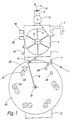
- the thread delivery device shown in FIGS. 1 to 3 has a housing 1, which carries a holder 2, which is set up for attachment to the frame ring of a circular knitting machine, not further shown, and in the area of which electrical connection devices for the inside of the Housing 1 housed electrical and electronic components are arranged.
- an electric stepping motor 3 is arranged in the manner shown in FIG. 3, which projects with its shaft through a corresponding opening in the front wall of the housing and drives a thread wheel 5 which is non-rotatably mounted on the shaft.
- the thread wheel 4 consists of a hub 5 placed on the shaft and a number of essentially U-shaped wire brackets 6 connected to the end of the hub 4, each of which has an essentially axially parallel thread support part 7 and an adjoining run-in slope 8.
- the thread wheel 4 can also be designed in the form of a thread drum or a rod cage and carry an end disk indicated in Fig. 3 at 7a, in which the rods bent at one end in accordance with the chamfer 8 are anchored with their straight thread support part 7, as shown in Fig 3 is illustrated.
- the thread wheel 4 forming the thread delivery element is assigned fixed thread guide elements which are arranged on the housing 1 and consist of an inlet eyelet 10 provided on a housing-fixed holder 9 and a thread eyelet 11 arranged on the housing 1 on the thread outlet side of the thread wheel.
- the thread 12 coming from a thread source (not shown further), for example a spool, runs through the inlet eyelet 10 via an adjustable thread-disk brake 13 arranged on the holder 9 onto the thread wheel 4 in the region of the run-up bevels 8, which open up the thread windings that form push the thread support parts 7 of the stirrups or rods 6, on which a storage roll consisting of a number of thread turns is thus formed, which together with the narrow support areas 7 ensures an essentially slip-free entrainment of the thread 12 on the circumference of the thread wheel 4.
- a thread source for example a spool
- the thread 12 runs tangentially from the thread wheel 4, namely at the same speed at which the thread also tangentially runs onto the thread wheel 4 through the inlet eyelet 10.
- the thread 12 coming from the storage reel on the thread wheel 4 runs through a thread eyelet 14 at the end of a thread guiding arm forming a movable thread tensioning element, at the other at 15 pivotably mounted on the housing 1, and from there back to the second stationary thread eyelet 11, which is at a distance below and is arranged next to the thread wheel 4.
- the thread goes from the second thread eyelet 11 to a thread consumer, not shown, in a knitting machine via the thread guide to the needles of a knitting point.
- the pivotably mounted thread guide arm 16 with its thread eyelet 14 between the circumference of the thread wheel 4 and the fixed second thread eyelet 11 normally forms the substantially V-shaped one shown in FIG. 1 extended thread path, which represents a thread reserve, the size of which depends on the angular position of the thread guide arm 16.
- the axis of rotation 15 of the thread guide arm 16 lies with the axis of the hub 5 of the thread wheel 4 in a common plane of symmetry, the arrangement being such that the thread guide arm 16 lying in this plane of symmetry in FIG. 1 has its eyelet 14 at a distance from the circumference of the thread wheel 4 is approximately at the level of the second fixed thread eyelet 11.
- the axis of the eyelet 14 extends in this position of the thread guide arm 16 in the vertical direction.
- a small DC motor 18 (FIG. 3) is fastened to the front wall of the housing, which projects with its shaft 190 through a corresponding opening in the front wall of the housing and is rotatably coupled to the thread guide arm 16 which is bent inwards at its open end.
- the permanently excited DC motor 18, which is preferably designed as a so-called bell-rotor motor, acts as an electrical torque transmitter and can also be replaced by a torque transmitter constructed similarly to the measured value of a moving-coil measuring instrument etc. It exerts on the thread guide arm 16 a precisely predetermined, adjustable pretensioning torque, which corresponds to a corresponding pretensioning force acting on the eyelet 14, with which the thread guide arm 16 is acted upon.
- This pretensioning force is opposite to the tensile force exerted by the thread 12 guided through the eyelet 14 and dependent on the thread tension, ie with reference to FIG. 1 this pretensioning force points to the left or the pretensioning torque is directed counterclockwise.
- a transducer in the form of a first electro-optical signal transmitter 19 is coupled, which thus senses the angular position of the thread guide arm 16 and emits an electrical signal which characterizes this and thus also the size of the thread reserve mentioned above.
- a second electro-optical signal transmitter 20 of the same design referred to as a position transmitter, on the shaft 190, which likewise generates a signal which characterizes the angular positions of the thread guide arm 16 and the meaning of which will be explained in more detail below.
- Each of the two signal transmitters 19, 20 consists in each case of a light-emitting diode 21 or 22 and a phototransistor 23 or 24 located in the beam path of the light-emitting diode, the light-emitting diodes 21, 22 and the phototransistors 23, 24 being seated on a holder 25 fixed to the housing.
- the pivoting movement of the thread guide arm 16 is limited in both directions of rotation by two stop pins 28, 29, which can be seen in the example from FIG. 1, both close to each other at a distance to the right of the axis of symmetry containing the axis of the hub 5 and the axis 15 of the thread guide arm 16 are arranged such that when the thread guide arm 16 abuts the stop pin 28 or 29, the eyelet 14 is at a certain lateral distance from the second fixed thread eyelet 11.
- the thread guide arm 16 can thus execute a pivoting movement limited to approximately 60 ° in a clockwise direction, while its counterclockwise mobility encompasses an angular range of approximately 280 °.
- a support plate 30 coaxial to the axis 15 is fastened, which has a central opening 31 allowing the passage of the shaft 190 and the radius of which is somewhat larger than the length of the thread guide arm 16 two mentioned stop pins 28, 29 are arranged, on which the thread guide arm 16 only comes into contact in the event of a malfunction and to which switching means (not shown further) are assigned, by means of which a shutdown or warning signal is emitted, and the thread guide arm 16 on one of the stop pins 28, 29 Facility is coming.
- the carrier disk 30 carries on its front side protruding and in pairs adjacent thread support elements 32, 33, of which the first thread support elements 32 and the second thread support elements 33 each lie on a common circle 34 and 35, which is coaxial with the axis 15 and in are an angular distance of about 60 ° apart.
- the diameter of the circle 34 is larger than that of the circle 35; the diameter of both circles 34, 35 is smaller than the radius of the circle described by the eyelet 14 when the thread guide arm 16 rotates about the axis 15.
- the thread support elements 32, 33 together form a thread support for an additional thread reserve. They are each designed in the form of cylindrical rollers which carry a thread receiving or guiding groove 350 which is V-shaped in cross section on the circumference.
- the outer thread support elements 32 are arranged in a rotationally fixed manner on the carrier disk 30, while the radially inner thread support elements 33 are rotatably mounted on bearing bolts 36 arranged on the carrier disk 30 above.
- all the thread support elements 32, 33 could either be held in a rotationally fixed manner or rotatably mounted.
- the length of the bearing bolts 36 is chosen such that with two thread support elements 32, 33 assigned to each other in pairs, the radially inner thread support element 33 stands axially next to the thread support element 32, as can be seen from FIG. 3.
- the thread guide arm 16 is angled such that it can freely overlap the protruding thread support elements 32, 33; his eyelet 14 lies with their inner edge within the axial extent, ie within the V-shaped groove 350 of the radially outer thread support elements 32, the eyelet 14 being movable even at a small radial distance from these thread support elements 32.
- the thread support elements 33 which are located radially on the inside with respect to the axis 15, lie with the apex of their V-shaped groove 350 in a common vertical plane which runs either through the axis of the fixed eyelet 11 or at a small lateral distance from it.
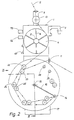
- This configuration of the arrangement of the thread support elements 32, 33 ensures that when the thread guide arm 16 swivels counterclockwise from the operating position shown in FIG. 1 into the return position of the thread 12 shown in FIG. 2 on the thread path between the thread wheel that is then stationary 4 and the fixed second thread eyelet 11 is placed on the thread support elements 32, 33 arranged at equal angular intervals, forming an additional thread reserve.
- the additional thread reserve thus formed is simply released by pulling thread through the thread eyelet 11, with the result that, starting from the position shown in FIG. 2, the thread guide arm 16 rotates clockwise and the thread continuously from the thread support elements 32 , 33 is lifted until the operating position according to FIG. 1 is reached, in which the thread wheel 4 delivers thread again.
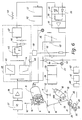
- the thread guide arm 16 with the coupled DC motor 18 and the first signal transmitter 19 serving as a measuring transducer are part of a regulator which regulates the thread tension on the outlet side of the thread wheel 4 to a constant value predetermined by the torque of the DC motor 18.
- Control circuit 39 fed in which processes the signal and on the output side generates a frequency signal of a specific pulse repetition frequency, which is indicated at 40 and is fed to control electronics 41, which feeds a control signal in the form of a corresponding step pulse sequence to the stepping motor 3 via a downstream power output stage 42.
- the low-pass filter 37 filters out higher-frequency interference signals from the analog signal coming from the signal transmitter 19; on the output side, the voltage follower 38 supplies a signal voltage potential which has a relatively low output impedance and which is dependent on the respective angular position of the thread guide arm 16.
- This voltage potential is applied to a circuit arrangement of the circuit part 39 which essentially consists of two integrators 43, 44 and which has a time constant which is matched to the respective starting or stopping characteristics of the stepping motor and thus the temporal change in the frequency of the frequency signal 40 during startup or of the outlet of the stepping motor 3 is limited in such a way that the stepping motor 3 loaded by the thread 12 and the thread wheel 4 etc. can follow the frequency change.
- the thread consumer can cover his thread requirement from the thread reserve, the thread tension and the torque of the direct current motor 18 which is independent of the setting angle and which specifies the target value always being kept at its target value.
- the stepping motor 3 can adjust the thread wheel to the thread speed required during this time Accelerate speed within a time, the length of which is determined by the start-up characteristic and which ensures that the stepper motor remains in step with the frequency signal 40.
- the integrator 43 limits the speed of the frequency change when the stepping motor 3 starts up, while the integrator 44 limits the speed of the frequency change to a value which is below the stopping characteristic of the stepping motor 3, so that it stops exactly the frequency change of the frequency signal 40 until it stops follows.
- the circuit arrangement formed by the integrators 36, 37 is followed by a diode path 45, the output of which is connected via a low-pass filter 46 to a voltage / frequency converter 47 which supplies the frequency signal 40.
- the diode path 45 forms a threshold circuit which prevents the voltage / frequency converter 47 from being supplied with signal voltages below a lower threshold value, which would result in a frequency signal with an impermissibly low frequency being output for the stepping motor 3.
- the low-pass filter 46 prevents malfunctions of the voltage / frequency converter 47, which is designed on the output side with a zero point suppression and which has a characteristic curve that can be changed in order to adjust the angular position of the thread guide arm 16 and thus the size of the thread reserve for a specific stationary thread running speed accordingly can.
- the analog output from the voltage follower 38 The voltage signal is also fed via a potentiometer 48 to a differentiator 49, where it is differentiated.
- the output of the differentiating element 49 is connected via an adder 50 and a voltage follower 51 to a second potentiometer 52, which makes it possible to set the magnitude of the torque exerted by the direct current motor 18 and thus the nominal value of the thread tension.
- the control input of a constant current source 53 is connected to the potentiometer 45 and excites the direct current motor 18 with constant current via a power output stage 54.
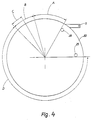
- the thread guide arm 16 moves in the work area designated by A in FIG. 4, which in the selected embodiment extends over an angular range of approximately 45 ° and clockwise through the stop pin 28 and counterclockwise through a so-called
- the storage area B is limited by approximately 30 ° here, which is characterized in that when the thread guide arm 16 assumes a position ("limit position") lying within the storage area B, ie immersed in the storage area B, the stepper motor 3 is stopped.
- the thread guide arm 16 begins to migrate from its desired angular position corresponding to the respective thread speed, so that the analog voltage signal fed to the switching part 39 undergoes a corresponding change.
- the corresponding pulse control signal 40 for the stepper motor 3 generated in the circuit part 39 is accordingly changed in the sense that the stepper motor 3 changes its speed and thus also the thread delivery speed until a steady state is reached again, in which the thread guide arm 16 assumes a fixed angular position in which the thread pulling force exerted by the thread via the eyelet 14 on the thread guide arm 15 keeps the torque exerted by the direct current motor 18 in equilibrium.
- the controller has an integrating effect.
- the damping acting on the thread guide arm 16, which is essentially proportional to its angular velocity during a pivoting movement, is generated either by the DC motor 18, which has a correspondingly low internal resistance, or by its own damping device of a known type, not shown.
- an external signal source for example one Central control device for all or for a certain number of thread delivery devices of a circular knitting machine
- the control input of the constant current source 53 is fed via the potentiometer 52, an external control signal which allows remote adjustment of the torque of the DC motor 18 and thus the thread tension.
- Measuring sockets 56, 57 allow a speed signal which is proportional to the step frequency of the step motor 3 and which characterizes the speed of the step motor and a signal which indicates the input voltage of the constant current source 53 and thus the constant current feeding the direct current motor 18 and thus the torque emitted by the direct current motor to be removed and fed to an external display source, which allows an immediate reading and control of the thread running speed (thread quantity per unit time) and the thread tension.
- the differentiator 49 supplies a compensation signal, the size of which is set via the potentiometer 48 and which is added to the actuating signal of the DC motor 18 via the adder 50. It has the effect that, in particular in the case of small thread tension settings, the excitation of the direct current motor 18 is additionally increased or decreased temporarily in the sense of reducing this control deviation when a control deviation occurs.
- the electronics 58 act in such a way that the potential at the control input of the constant current source 53 is lowered by a predetermined, possibly adjustable value, and the thread guide arm 16 enters a partial area C of reduced thread tension within the storage area B.
- the purpose of this measure is as follows:
- the thread guide arm 16 penetrates into the storage area B with its inherent inertia until the stepping motor 3 has come to a standstill and the thread is tensioned again and thus preventing the further movement of the thread guide arm 16.
- the exact position or depth of penetration that the thread guide arm reaches in the storage area B depends, among other things, on the thread speed and thread tension and how quickly the thread take-up was interrupted. If the thread guide arm 16 remains in the part B -C of the storage area B adjoining the work area A, the thread tension remains at the setpoint set by the potentiometer 52, which also applies to the knitting operation, when the stepping motor 3 is stopped.
- the knitting machine is now unable to hold the thread under this thread tension because, for example, the thread clamp of the striping apparatus gives way slightly, the will move Thread guide lever 16 under the effect of the setpoint biasing force exerted by the DC motor 18 slowly, with reference to FIG. 1.4, to the left.
- the electronics 58 automatically reduces the thread tension by a corresponding reduction in the excitation of the DC motor 18 to a much smaller value, which is so small that the tensile force exerted by the thread is harmless .
- the thread tension is not zero, because otherwise the thread breaker would respond.
- the thread tension in the area of the movement of the thread guide arm 16 comprising the working area A and part of the storage area B is constant and equal to the desired value; it is lowered only in the sub-area C of the storage area B.
- the thread delivery device described so far supplies the thread with constant thread tension to the thread consumer with continuous thread consumption even at different thread speeds, the thread guide arm 16 moving in the working area A (FIG. 4). If the thread consumption is interrupted, for example when the machine is at a standstill or when the thread is laid out in a knitting machine working with a striping apparatus, the thread guide arm 16, as already explained, enters the storage area B, in which the stepping motor is stopped and the thread going to the thread consumer first below the normal setpoint thread tension is held. If, under the effect of this thread tension, the thread is withdrawn somewhat and the thread guide arm thus enters area C of reduced thread tension, the thread tension is reduced to a small value, as has also already been explained.
- the thread delivery device is used for a flat knitting machine or a circular knitting machine (sock or hosiery machine) working in a pendulum way
- the slide or the needle cylinder begins its return movement after reaching the reversal point of movement, because of the shortening of the thread travel path from the fixed outlet thread eyelet 11 to the thread guide practically first returned thread.
- the thread return decreases, so that the thread guide arm 16 is moved counterclockwise under the effect of the torque exerted by the direct current motor 18, in relation to FIG. 4, and thereby in FIG. 4 marked with D occurs further movement range, which can also be referred to as "thread return range".
- Electronics 58 were previously switched off by a manually operated switch 60 (Fig. 1, 6).
- the dimming disk 26 assigned to the first signal transmitter 19 can also be designed such that when the thread guide arm 16 reaches a certain position within the storage area B, it controls the phototransistor 23 in such a way that it no longer delivers an analog signal causing the electronics 58 to respond.
- the second signal transmitter 20 acting as a position transmitter becomes effective, the photo transistor 24 of which emits a signal which characterizes the angular position of the thread guide arm 16.
- This signal is fed to a voltage follower 61 via a low-pass filter 60 which filters out disturbances, which is followed by an electronic thread tension increasing circuit 62 which, via a diode 63 and an adding circuit indicated by a resistor 64, applies an increased potential to the control input of the constant current source 53.
- the torque exerted by the direct current motor 18 is increased, with the result that the thread guide arm 16 pulls back the thread coming back from the thread consumer through the thread eyelet 11 with increased tensile force and in the course of its counter-clockwise rotational movement in relation to FIG. 1 described way on the thread support elements 32, 33.
- the movement of the thread guide arm 16 comes to a standstill as soon as the entire thread which has been retrieved is introduced into the additional thread reserve. Should the additional thread reserve to accommodate the Returned thread is not sufficient or if there is a thread break, the thread guide arm 16 finally comes to rest on the stop pin 29, the associated switching means of which are actuated, thus emitting the shutdown signal.
- the electronic circuit parts 60, 61, 62 are illustrated in detail in FIG. 7:
- a voltage follower 61 designed in the form of an IC (LM 324), the output of which is connected via a resistor and a capacitor 67 with a differentiating element 68, to the emitter of the phototransistor 24 via a low-pass filter 60 formed by a capacitor 64 and a resistor 65 is connected, which has a capacitor 69 and a resistor 70 and a diode 71 which is connected to a voltage divider formed by two resistors 72, 73.
- a comparator 74 formed by an IC (LM 324), which is connected via a diode 75 and a monoflop 76 (IC LM 324) to the input of an amplifier 77 (IC LM 324).
- the output of the amplifier 27 is connected via a potentiometer 78 and the diode 63 and the adder 64 to the control input 79 of the constant current source 53.
- the second signal generator 20 indicates by the analog signal emitted by the phototransistor 24 that the thread guide arm 16 has entered the return area D, this analog signal is amplified in the voltage follower 61 and then differentiated in the differentiator 68.
- the differentiator 68 in turn emits a signal only as long as the thread guide lever 16 is in motion, specifically counterclockwise with respect to FIG. 1.
- the change in time of the analog signal required for this is achieved by the special shape of the track or edge of the anti-glare plate 27 scanned by the light barrier 22, 24.
- the downstream comparator 74 integrates the signal emitted by the differentiator 68 and passes this information on to the monoflop 76 in the form of a constant positive voltage level.
- a positive potential appears which is amplified by the amplifier 77 and applied to the control input 79 of the constant current source 53 via the setting potentiometer 78 and the adder 64.
- the potentiometer 78 makes it possible to set the thread tension increase required in each case for the return of the thread.
- the arrangement can be simplified to simplify the construction also be such that only a single cover plate 80 (FIG. 5) is provided, which carries the traces scanned by the two light barriers 21, 23 and 22, 24 on different radii, as illustrated in FIG. 5.
- the essentially eccentric track 26a formed by the outer peripheral edge corresponds to that of the cover disk 26 of the first signal transmitter 19, while the inner track 27a is designed according to that of the anti-mask disk 27 of the second signal transmitter 20.
- the radially inner track 27a Since it would be difficult for constructional reasons to produce the radially inner track 27a continuously over its entire circumferential area without connection to the radially outer disk areas, it is composed of individual eccentric sections 27b, which at 81 each with the radially outer surrounding disk material via a radial shoulder or an acute-angled transition are connected.
- the monoflop 76 for example set to 10 ms, now prevents a brief interruption of the signal flow due to the small anti-glare areas at 81 when the anti-glare disk 80 transitions from one eccentric track 27b to the next following one when the thread guide arm 16 moves.
- This division of the track 27a into successive eccentric functions also enables a relatively large voltage increase per unit time of the analog signal to be achieved when the shield 80 rotates, so that the differential quotient (dU / dt) generated by the differentiator 68 also has a size which is sufficient for the functional reliability.
Abstract
Eine Fadenliefervorrichtung für Textilmaschinen, insbesondere Strick- und Wirkmaschinen, weist ein den Faden (12) schlupflos förderndes, drehbar gelagertes Fadenlieferelement (4) auf, das mit einem drehzahlregelbaren elektrischen Antriebsmotor (3) gekuppelt ist. Im Fadenlaufweg hinter dem Fadenlieferelement ist ein auf den von dem Fadenlieferelement kommenden Faden einwirkendes Fadenspannelement (16) angeordnet, das beweglich gelagert und mit einer die Fadenspannung bestimmenden Vorspannkraft beaufschlagt ist, wobei zwischen dem Fadenspannelement und wenigstens einem Fadenleitelement (11) eine Fadenreserve ausgebildet ist, deren Größe durch die jeweilige Stellung des Fadenspannelementes bestimmt ist. Das Fadenspannelement ist mit einem Meßwertgeber (19) gekuppelt, der in Abhängigkeit von der innerhalb eines Arbeitsbereiches (A) erfolgenden Verstellbewegung des Fadenspannelements ein für dessen jeweilige Stellung und/oder Bewegung kennzeichnendes Signal an eine den Antriebsmotor enthaltende elektrische Schaltung abgibt, durch die der Antriebsmotor stillsetzbar ist, wenn das Fadenspannelement bei einer Bewegung im Sinne einer größer werdenden Fadenreserve eine Grenzstellung (A/B) seines Arbeitsbereiches erreicht. Anschließend an diese Grenzstellung ist ein weiterer Bewegungsbereich (D) des Fadenspannelementes vorgesehen, in dem Fadenauflagemittel (32,33) angeordnet sind,auf denen der von dem Fadenspannelement zurückgeführte und unter Spannung gehaltene Faden unter Ausbildung einer zusätzlichen Fadenreserve vorübergehend ablegbar ist.A thread delivery device for textile machines, in particular knitting and warp knitting machines, has a thread delivery element (4), which supports the thread (12) without slippage, and which is coupled to a speed-adjustable electric drive motor (3). A thread tensioning element (16) acting on the thread coming from the thread delivery element is arranged in the thread path behind the thread delivery element, said thread tensioning element being movably mounted and subjected to a prestressing force determining the thread tension, a thread reserve being formed between the thread tensioning element and at least one thread guide element (11). whose size is determined by the respective position of the thread tensioning element. The thread tensioning element is coupled to a transducer (19) which, depending on the adjustment movement of the thread tensioning element taking place within a working area (A), emits a signal characterizing its respective position and / or movement to an electrical circuit containing the drive motor, through which the drive motor It can be stopped when the thread tensioning element reaches a limit position (A / B) of its working area during a movement in the sense of an increasing thread reserve. Subsequent to this limit position, a further movement range (D) of the thread tensioning element is provided, in which thread support means (32, 33) are arranged, on which the thread returned and held under tension by the thread tensioning element can be temporarily deposited while forming an additional thread reserve.
Description
Die Erfindung betrifft eine Fadenliefervorrichtung für Textilmaschinen mit zeitlich unterschiedlichem Fadenbrauch, insbesondere Strick- und Wirkmaschinen, mit einem den Faden schlupflos fördernden, drehbar gelagerten Fadenlieferelement, dem Fadenleitelemente zugeordnet sind und das mit einem drehzahlregelbaren elektrischen Antriebsmotor gekuppelt ist, mit einem im Fadenlaufweg hinter dem Fadenlieferelement angeordneten, auf den von dem Fadenlieferelement kommenden Faden einwirkenden Fadenspannelement, das beweglich gelagert und mit einer die Fadenspannung bestimmenden Vorspannungskraft beaufschlagt ist, wobei zwischen dem Fadenspannelement und wenigstens einem Fadenleitelement eine Fadenreserve ausgebildet ist, deren Größe durch die jeweilige Stellung des Fadenspannelementes bestimmt ist, sowie mit die Drehzahl des Antriebsmotors abhängig von dem Fadenverbrauch des Fadenverbrauchers regelnden elektrischen Regelmitteln.The invention relates to a thread delivery device for textile machines with different times of thread usage, in particular knitting and warp knitting machines, with a rotatably mounted thread delivery element which promotes the thread without slippage, to which thread guide elements are assigned and which is coupled to a speed-adjustable electric drive motor, with a thread path behind the thread supply element arranged, acting on the thread coming from the thread supplying thread tensioning element, which is movably mounted and is subjected to a prestressing force determining the thread tension, a thread reserve being formed between the thread tensioning element and at least one thread guide element, the size of which is determined by the respective position of the thread tensioning element, and with the speed of the drive motor depending on the thread consumption of the thread consumer regulating electrical control means.
Beispielsweise bei Flachstrickmaschinen führt der die Nadelschloßteile tragende und mit diesen die Nadelbewegung steuernde Schlitten eine hin- und hergehende Bewegung über die wirksame Breite des Nadelbettes aus. Um den Faden ordnungsgemäß in die Haken der ausgetriebenen Nadeln einzulegen, muß auch der Fadenführer entsprechend hin- und herbewegt werden. Im Bereiche seiner Bewegungsumkehrstellen macht der Schlitten bezüglich der jeweils zuletzt strickenden Nadeln einen Überhub, während dessen Dauer kein Faden verarbeitet und damit von der Fadenquelle abgenommen wird. Außerdem erfährt die Länge des Fadenlaufweges zwischen der ortsfesten Fadenquelle und dem eine lineare, hin- und hergehende Bewegung ausführenden Fadenführer eine dauernde Veränderung. Um zu vermeiden, daß sich hierbei aus dem jeweils zeitweilig überschüssigen Fadenmaterial eine Schlaufe bildet, wird in der Praxis ein sogenannter Fadenspanner verwendet, der das nicht benötigte Fadenmaterial solange in eine Fadenreserve aufnimmt und es in dieser unter Spannung hält, bis nach Abschluß der Umkehrbewegung des Schlittens und des Fadenführers die erste Nadel wieder strickt bzw. die gebildete Fadenreserve zufolge der im weiteren Bewegungsverlauf wieder größer werdenden Länge des Fadenlaufwegs zu dem Fadenführer aufgelöst wird. Grundsätzlich ähnliche Verhältnisse treten bei der Herstellung von Socken und Strümpfen mit Ferse und Spitze auf Kleinrundstrickmaschinen auf, wenn der Nadelzylinder zum Stricken der Ferse oder der Spitze im sogenannten Pendelgang in Umfangsrichtung hin- und herbewegt wird.For example, in flat knitting machines, the carriage carrying the needle lock parts and using them to control the needle movement executes a reciprocating movement over the effective width of the needle bed. To properly insert the thread into the hooks of the expelled needles, the Thread guides are moved back and forth accordingly. In the area of its reversal of movement, the carriage makes an overstroke with respect to the last knitting needles, during which no thread is processed and is therefore removed from the thread source. In addition, the length of the thread travel path between the stationary thread source and the thread guide carrying out a linear, reciprocating movement undergoes a permanent change. In order to avoid that a loop is formed from the temporarily excess thread material, a so-called thread tensioner is used in practice, which holds the thread material that is not required in a thread reserve and keeps it under tension until after the reversing movement of the The first needle is knitted again on the carriage and the thread guide, or the thread reserve formed is released due to the length of the thread path to the thread guide, which length increases as the movement continues. Basically similar conditions occur in the manufacture of socks and stockings with heels and toes on small circular knitting machines if the needle cylinder for knitting the heel or toe is moved back and forth in the so-called pendulum movement in the circumferential direction.
Diese Fadenspanner arbeiten mit Fadenbremsen und haben den grundsätzlichen Nachteil, daß sie keine gleichbleibende Fadenspannung gewährleisten können. Dies hat zur Folge, daß die Maschengröße unterschiedlich wird, mit dem Ergebnis, daß bspw. so hergestellte Socken und Strümpfe unterschiedlich lang werden und deshalb nach der Fertigstellung paarweise auf gleiche Länge sortiert werden müssen.These thread tensioners work with thread brakes and have the fundamental disadvantage that they cannot guarantee a constant thread tension. As a result, the mesh size becomes different, with the result that, for example, socks produced in this way and stockings are of different lengths and must therefore be sorted in pairs to the same length after completion.
Mit einer Fadenbremse arbeitet auch eine aus der FR-OS 2538 419 bekannte Fadenrückholvorrichtung für Flachstrickmaschinen oder im Pendelgang arbeitende Strumpf- oder Sockenstrickmaschinen, bei der die Fadenspannung auf dem Fadenlaufweg zwischen einem feststehenden Fadenleitelement und dem Fadenführer abgetastet und eine in dem Fadenlaufweg vor dem feststehenden Fadenleitelement angeordnete Fadenbrems- und -rückholeinrichtung derart verstellt wird, daß die Fadenspannung an dem Fadenführer näherungsweise innerhalb eines vorbestimmten Schwankungsbereiches bleibt. Abgesehen davon, daß diese mit von dem Fadenabtastelement gesteuerten Grenzwertschaltern arbeitende Einrichtung nur eine sehr unvollkommene und grobe Beeinflussung der Fadenspannung gestattet, muß der Faden von den Nadeln selbst über die Fadenbremse von der Spule abgezogen werden, so daß der Faden nur mit einer verhältnismäßig großen Fadenspannung verarbeitet werden kann. Außerdem können Störungen der Fadenablaufverhältnisse von der Spule die Gleichmäßigkeit der gestrickten Ware beeinträchtigen.With a thread brake also works a thread retrieval device known from FR-OS 2538 419 for flat knitting machines or hosiery or sock knitting machines operating in the pendulum, in which the thread tension is sensed on the thread path between a fixed thread guide element and the thread guide and one in the thread path in front of the fixed thread guide element arranged thread braking and return device is adjusted such that the thread tension on the thread guide remains approximately within a predetermined fluctuation range. Apart from the fact that this device, which operates with limit switches controlled by the thread sensing element, permits only a very imperfect and rough influence on the thread tension, the thread must be drawn from the needles themselves via the thread brake from the bobbin, so that the thread only with a relatively large thread tension can be processed. In addition, disturbances in the thread run-off conditions from the bobbin can impair the uniformity of the knitted goods.
Diesem Nachteil ist bei einer aus der US-PS 3962 891 bekannten Fadenliefervorrichtung für eine Flachstrickmaschine,von der die Erfindung ausgeht, dadurch abgeholfen, daß sie ein im Fadenlaufweg der Fadenspule nachgeordnetes, den Faden schlupflos förderndes, drehbar gelagertes Fadenlieferelement aufweist, das von einem elektrischen Antriebsmotor angetrieben ist und den Faden dem Fadenführer und damit den Nadeln zuliefert. Die Anordnung ist dabei derart getroffen, daß mit den Antriebselementen des Schlittens und des Fadenführers der Flachstrickmaschine Weggeber verbunden sind, die für die jeweilige Stellung und Geschwindigkeit des Schlittens und des Fadenführers kennzeichnende elektrische Signale abgeben, mit deren Hilfe der Antriebsmotor des Fadenlieferelementes, unter Berücksichtigung der sich bei der Hin- und Herbewegung des Fadenführers ergebenden Veränderungen des Fadenlaufwegs zu dem Fadenführer, entsprechend dem zeitlichen Verlauf des Fadenverbrauches gesteuert wird. Dazu liegt der Antriebsmotor als Stellglied in einer elektrischen Regelschleife, deren Führungsgröße durch die erwähnten Signale gebildet ist. Um zu vermeiden, daß während der bei der Bewegungsumkehr Fadenführers auftretenden Beschleunigungs- und Verzögerungsphasen des Antriebsmotors Fadenspannungsschwankungen auftreten, die wegen der trägen Masse des Antriebsmotors durch Änderungen der Drehzahl des Fadenlieferelementes nicht ausgeglichen werden können, ist dem Fadenlieferelement im Fadenlaufweg ein Fadenspannelement nachgeordnet, das beim Nachlassen der Fadenspannung vorübergehend eine Fadenreserve aufbaut, die im weiteren Betriebsablauf jeweils wieder abgebaut wird. Dieses Fadenspannelement ist in Gestalt eines um eine ortsfeste Drehachse dreh- oder schwenkbar gelagerten Fadenführarms ausgebildet, der endseitig eine Fadenöse trägt, die im Zusammenwirken mit feststehenden Fadenleitelementen einen etwa V-förmigen Fadenlaufweg erzeugt. Der Fadenführarm ist im Bereiche seiner Lagerstelle mit einer einenends ortsfest verankerten Spiralfeder gekuppelt, die auf den Fadenführarm eine einstellbare vorbestimmte Vorspannkraft ausübt, welche die Größe der Fadenspannung bestimmt. Der Anbau der verschiedenen Weggeber an der Flachstrickmaschine erfordert Eingriffe in die Maschine. Darüber hinaus sind diese Weggeber notwendigerweise deshalb aufwendig, weil sie die gesamte Hubbewegung des Schlittens und des Fadenführers über das häufig verhältnismäßig lange Nadelbett erfassen und obendrein zumindest teilweise entsprechend der Breite des jeweils gearbeiteten Warenstückes einstellbar sein müssen. Da der Antriebsmotor des Fadenlieferelementes lediglich in starrer vorgegebener Abhängigkeit von der Hin- und Herbewegung des Schlittens und des Fadenführers gesteuert ist, sind die Abstimmung und die Einjustierung der einzelnen Glieder der Steuerkette kritisch.This disadvantage is remedied in a yarn delivery device for a flat knitting machine known from US Pat. No. 3,962,891, from which the invention is based, in that it has a rotatably mounted, rotatably mounted yarn delivery element in the yarn path of the yarn bobbin that supports the yarn without slippage is driven by an electric drive motor and delivers the thread to the thread guide and thus to the needles. The arrangement is such that travel sensors are connected to the drive elements of the carriage and the thread guide of the flat knitting machine, which emit characteristic electrical signals for the respective position and speed of the carriage and the thread guide, with the help of which the drive motor of the thread delivery element, taking into account the changes occurring during the back and forth movement of the thread guide changes in the thread path to the thread guide, is controlled in accordance with the temporal course of the thread consumption. For this purpose, the drive motor is an actuator in an electrical control loop, the reference variable of which is formed by the signals mentioned. In order to avoid that during the acceleration and deceleration phases of the drive motor occurring during the movement reversal of the drive motor, thread tension fluctuations occur which cannot be compensated for by changes in the speed of the thread delivery element due to the inertial mass of the drive motor, a thread tensioning element is arranged after the thread delivery element in the thread travel path If the thread tension decreases, a thread reserve temporarily builds up, which is reduced again in the further course of operation. This thread tensioning element is designed in the form of a thread guide arm which is rotatably or pivotably mounted about a fixed axis of rotation and which carries a thread eyelet at the end which, in cooperation with fixed thread guide elements, generates an approximately V-shaped thread path. The thread guide arm is coupled in the area of its bearing point to a spiral spring which is fixed at one end and which is an adjustable predetermined one on the thread guide arm Exerts pre-tension, which determines the size of the thread tension. The installation of the various displacement sensors on the flat knitting machine requires intervention in the machine. In addition, these displacement sensors are necessarily expensive because they capture the entire lifting movement of the carriage and the thread guide over the often relatively long needle bed and, moreover, must be at least partially adjustable according to the width of the work piece being processed. Since the drive motor of the thread delivery element is controlled only in a rigid, predetermined dependency on the reciprocating movement of the carriage and the thread guide, the coordination and the adjustment of the individual links of the control chain are critical.
Ausgehend von diesem Stand der Technik liegt der Erfindung die Aufgabe zugrunde, eine Fadenliefervorrichtung für Textilmaschinen mit zeitlich unterschiedlichem Fadenverbrauch, bspw. Flachstrickmaschinen oder zeitweilig im Pendelgang arbeitende Rundstrickmaschinen etc. zu schaffen, die es gestattet, ohne Eingriffe in die Maschine eine Fadenlieferung mit konstanter, beliebig einstellbarer Fadenspannung auch unter Betriebsbedingungen zu gestatten, under denen etwa im Zusammenhang mit der Bewegungsumkehr des Fadenführers einer Flachstrickmaschine oder des Nadelzylinders einer Rundstrickmaschine eine vorübergehende Schlaufenbildung des Fadens oder das Auftreten übermäßiger Fadenspannungsspitzen sicher verhindert sind.On the basis of this prior art, the object of the invention is to create a thread delivery device for textile machines with different times of thread consumption, for example flat knitting machines or circular knitting machines etc. which temporarily work in a pendulum motion, which allows a thread delivery with constant, Allow thread tension that can be set as desired, even under operating conditions, which, for example in connection with the reversal of movement of the thread guide of a flat knitting machine or the needle cylinder of a circular knitting machine, reliably prevent a temporary formation of loops in the thread or the occurrence of excessive thread tension peaks.
Zur Lösung dieser Aufgabe ist die eingangs genannte Fadenliefervorrichtung erfindungsgemäß dadurch gekennzeichnet, daß das Fadenspannelement mit einem Meßwertgeber gekuppelt ist, der in Abhängigkeit von der innerhalb eines Arbeitsbereiches erfolgenden Verstellbewegung des Fadenspannelements ein für dessen jeweilige Stellung und/oder Bewegung kennzeichnendes Signal an eine den Antriebsmotor enthaltende elektrische Schaltung abgibt, durch die der Antriebsmotor stillsetzbar ist, wenn das Fadenspannungselement bei einer Bewegung im Sinne einer größer werdenden Fadenreserve eine Grenzsstellung seines Arbeitsbereiches erreicht, daß anschließend an diese Grenzstellung des Arbeitsbereiches ein weiterer Bewegungsbereich des Fadenspannelementes vorgesehen ist, in den das Fadenspannelement bei nachlassender Fadenspannung durch die an ihm angreifende Vorspannkraft bei stillstehendem Antriebsmotor bewegbar ist und daß dem weiteren Bewegungsbereich Fadenauflagemittel zugeordnet sind, auf denen der von dem Fadenspannelement rückgeführte und unter Spannung gehaltene Faden unter Ausbildung einer zusätzlichen Fadenreserve vorübergehend ablegbar ist.To achieve this object, the thread delivery device mentioned at the outset is characterized according to the invention in that the thread tensioning element is equipped with a sensor is coupled, which, depending on the adjustment movement of the thread tensioning element taking place within a working area, emits a signal characterizing its respective position and / or movement to an electrical circuit containing the drive motor, by means of which the drive motor can be stopped if the thread tensioning element during a movement in the sense an increasing thread reserve reaches a limit position of its working area, that after this limit position of the working area a further movement range of the thread tensioning element is provided, into which the thread tensioning element can be moved with decreasing thread tension due to the pre-tensioning force acting on it with the drive motor at a standstill and that thread rest means are assigned to the further movement range are on which the thread returned from the thread tensioning element and kept under tension can be temporarily deposited with the formation of an additional thread reserve.
In der zusätzlichen Fadenreserve speichert das Fadenspannelement außerhalb seines normalen Arbeitsbereiches anfallendes Fadenmaterial bei stillstehendem Fadenlieferelement, so daß das Auftreten von Fadenschlaufen, bspw. bei der Bewegungsumkehr eines im Pendelgang arbeitenden Nadelzylinders, selbsttätig vermieden wird, ohne daß dazu zusätzliche Maßnahmen erforderlich wären. Dabei ist der Faden dauernd unter Spannung gehalten, so daß immer einwandfreie Fadenlieferverhältnisse gewährleistet bleiben.In the additional thread reserve, the thread tensioning element stores thread material occurring outside its normal working range when the thread delivery element is at a standstill, so that the occurrence of thread loops, for example when the movement of a needle cylinder working in the pendulum motion is avoided, without additional measures being necessary. The thread is kept under tension so that perfect thread delivery conditions are always guaranteed.
In einer bevorzugten Ausführungsform ist das Fadenspannelement Teil eines die Fadenspannung auf dem Fadenlaufweg hinter dem Fadenlieferelement konstant auf einem durch die Vorspannkraft gegebenen Sollwert haltenden Regler, wobei der Meßwertgeber bei einer Bewegung des Fadenspannelementes innerhalb des Arbeitsbereiches ein für die Stellgröße der Regelschleife kennzeichnendes Signal an die als Teil der Regelstrecke arbeitende elektronische Schaltung abgibt. Unter normalen Betriebsverhältnissen, bspw. beim Rundstricken oder während der Schlitten der Flachstrickmaschine über das Nadelbett fährt, wird über das sich lediglich innerhalb seines Arbeitsbereiches bewegende Fadenspannelement und den Regler der Antriebsmotor des Fadenlieferelementes dauernd derart geregelt, daß die Fadenspannung konstant auf die durch die auf das Fadenspannelement wirkende Vorspannkraft bestimmte Sollwertgröße eingeregelt bleibt. Sowie der Schlitten aber seinen Überhub hinter der letzten strickenden Nadel und seine anschließende Bewegungsumkehr ausführt, wandert das Fadenspannelement unter der Wirkung der Vorspannkraft in den zusätzlichen Bewegungsbereich, während der Antriebsmotor des Fadenlieferelementes stillgesetzt ist. Es holt den nicht mehr abgenommenen Faden zurück und legt ihn auf die Fadenauflage auf, bis zufolge der Rückbewegung des Schlittens der Faden wieder abgenommen und damit zunächst die zusätzliche Fadenreserve aufgelöst und das Fadenspannelement wieder in seinen Arbeitsbereich zurückbewegt wird. Sowie es in diesen eintritt, wird der Antriebsmotor des Fadenlieferelementes wieder in Gang gesetzt und entsprechend dem Fadenverbrauch in seiner Drehzahl derart geregelt, daß die Fadenspannung stets konstant gehalten ist.In a preferred embodiment, the thread tensioning element is part of the thread tension on the Thread travel behind the thread delivery element constantly on a controller holding by the pretensioning force, the transducer emitting a signal characteristic of the manipulated variable of the control loop to the electronic circuit working as part of the controlled system when the thread tensioning element moves within the working range. Under normal operating conditions, for example when circular knitting or while the carriage of the flat knitting machine travels over the needle bed, the thread tensioning element and the controller, which only move within its working area, continuously regulate the drive motor of the thread delivery element in such a way that the thread tension is constantly adjusted to that caused by the Thread tensioning element acting prestressing certain setpoint size remains regulated. As soon as the slide carries out its overstroke behind the last knitting needle and its subsequent reversal of movement, the thread tensioning element moves under the effect of the pretensioning force into the additional movement range while the drive motor of the thread delivery element is stopped. It retrieves the thread that is no longer removed and places it on the thread support until the thread is removed again after the carriage has moved back and the additional thread reserve is thus first released and the thread tensioning element is moved back into its working area. As soon as it enters this, the drive motor of the thread delivery element is started again and its speed is regulated in accordance with the thread consumption in such a way that the thread tension is always kept constant.
Um bspw. eine Entscheidung darüber treffen zu können, ob der Fadenverbrauch lediglich vorübergehend vermindert oder eingestellt ist, oder ob ein Fadenbruch vorliegt, ist es zweckmäßig, wenn der weitere Bewegungsbereich des Fadenspannelementes durch einen Grenzwertsignalgeber begrenzt ist, der bei eine Maximalstellung erreichendem Fadenspannelement anspricht.In order to be able to make a decision, for example, whether the thread consumption is only temporarily reduced or set, or whether there is a thread break, it is expedient if the further range of movement of the thread tensioning element is limited by a limit signal transmitter which responds when the thread tensioning element reaches a maximum position.
Abhängig von den jeweiligen Gegebenheiten des Fadenlaufweges zwischen dem Fadenlieferelement und dem Fadenverbraucher, bspw. den Nadeln, greifen an dem Faden größere oder kleinere Reibungskräfte an, die von Umleitungen durch Fadenleitelemente etc. herrühren. Wenn deshalb der Faden von dem Fadenspannelement in die zusätzliche Fadenreserve zurückgezogen wird, müssen diese Reibungskräfte überwunden werden. Es ist deshalb häufig von Vorteil, wenn dem Fadenspannelement stellungsabhängig angesteuerte Mittel zugeordnet sind, durch die die auf das Fadenspannelement wirkende Vorspannkraft um einen gegebenenfalls einstellbaren vorbestimmten Wert erhöhbar ist, wenn das Fadenspannelement in seiner Bewegung eine vorbestimmte Stellung erreicht. Diese Stellung ist zweckmäßigerweise die vorerwähnte Grenzstellung des weiteren Bewegungsbereiches des Fadenspannelementes oder eine innerhalb dieses weiteren Bewegungsbereiches liegende Stellung. In bestimmten Fällen kann es auch zweckmäßig sein, diese Stellung noch innerhalb des Arbeitsbereiches des Fadenspannelementes vorzusehen. Diese Stellung des Fadenspannelementes läßt sich im übrigen konstruktiv einfach in der Weise ansteuern, daß mit dem Fadenspannelement ein Stellungsgeber gekuppelt ist, der bei Erreichen der vorbestimmten Stellung ein elektrisches Signal abgibt. Der Stellungsgeber kann zur weiteren Vereinfachung des Aufbaus auch mit dem Meßwertgeber vereinigt oder durch diesen gebildet sein, welcher ohnehin mit dem Fadenspannarm gekuppelt ist, um ein stellungsabhängiges Stellsignal für die Regelschaltung oder zumindest dann ein Stillsetzsignal für den Antriebsmotor des Fadenlieferelementes abzugeben, wenn das Fadenspannelement bei nachlassender Fadenspannung seine Grenzstellung zu dem weiteren Bewegungsbereich hin erreicht.Depending on the particular circumstances of the thread travel path between the thread delivery element and the thread consumer, for example the needles, larger or smaller frictional forces, which result from diversions through thread guide elements etc., act on the thread. Therefore, if the thread is withdrawn from the thread tensioning element into the additional thread reserve, these frictional forces have to be overcome. It is therefore often advantageous if the thread tensioning element is assigned position-dependent means, by means of which the biasing force acting on the thread tensioning element can be increased by an optionally adjustable predetermined value when the thread tensioning element reaches a predetermined position in its movement. This position is expediently the aforementioned limit position of the further range of movement of the thread tensioning element or a position lying within this further range of movement. In certain cases it may also be appropriate to provide this position within the working area of the thread tensioning element. This position of the thread tensioning element can be controlled in a structurally simple manner in such a way that a position transmitter is coupled to the thread tensioning element which emits an electrical signal when the predetermined position is reached. To further simplify the construction, the position transmitter can also be combined with or formed by the sensor, which is coupled to the thread tensioning arm anyway, in order to emit a position-dependent control signal for the control circuit or at least a stop signal for the drive motor of the thread delivery element when the thread tensioning element is at decreasing thread tension reaches its limit position towards the further range of motion.
Als konstruktiv zweckmäßig hat es sich erwiesen, wenn das Fadenspannelement einen drehbar gelagerten Fadenführarm aufweist, der mit dem Faden gekoppelt ist und mit dem ein die Winkelstellung des Fadenführarmes abtastender Meßwertgeber gekuppelt ist. Dieser meßwertgeber kann an sich beliebiger, vorzugsweise berührungslos arbeitender Bauart sein, doch hat es sich als vorteilhaft erwiesen, wenn der Meßwertgeber ein mit dem Fadenführarm gekuppeltes Winkelgeberelement aufweist, das durch fotooptische Signalgebermittel abtastbar ist. Dabei kann jede zweckentsprechende, auch für das statische und dynamische Regelverhalten des Reglers geeignete Übertragungsfunktion des Meßwertgebers mit einfachen Mitteln erzielt werden, wenn das Winkelgeberelement eine optisch abtastbare Spuren oder Kanten tragende Scheibe aufweist, von deren Spuren oder Kanten wenigstens eine dem Meßwertgeber und zumindest eine dem Stellungsgeber zugeordnet ist.It has proven to be structurally expedient if the thread tensioning element has a rotatably mounted thread guide arm which is coupled to the thread and with which a measuring sensor which couples the angular position of the thread guide arm is coupled. This transducer can be of any type, preferably non-contact, but it has proven to be advantageous if the transducer has an angular encoder element coupled to the thread guide arm which can be scanned by photo-optical signaling means. Any appropriate transfer function of the transmitter, which is also suitable for the static and dynamic control behavior of the controller, can be achieved with simple means if the angle transmitter element has an optically scannable disk or edge-bearing disk, of which at least one track or edge is attached to the transmitter and at least one is attached to it Position transmitter is assigned.
Wie bereits erläutert, ist es häufig zweckmäßig, beim Rückziehen des Fadens während des Aufbaus der zusätzlichen Fadenreserve die auf das Fadenspannelement wirkende Vorspannkraft zu erhöhen, um die auf dem Fadenlaufweg auf den Faden ausgeübte Bremskraft zu überwinden. Sowie jedoch der überschüssige Faden aufgenommen und auf den Fadenauflagemitteln abgelegt ist, entfällt die Notwendigkeit zur Beaufschlagung des Fadenspannelementes mit dieser erhöhten Vorspannkraft. Auch ist es in der Regel nicht erwünscht, bei der anschließenden Auflösung der zusätzlichen Fadenreserve wegen dieser erhöhten Vorspannkraft eine entsprechend erhöhte Fadenspannung in Kauf nehmen zu müssen. Um dies zu vermeiden, ist es vorteilhaft, wenn die Mittel zur Erhöhung der auf das Fadenspannelement wirkenden Vorspannkraft eine Einrichtung zur Feststellung des Bewegungszustandes und gegebenenfalls der Bewegungsrichtung des Fadenspannelementes aufweisen und durch diese Einrichtung die Erhöhung der Vorspannkraft lediglich bei bewegtem Fadenspannelement ermöglicht oder bewirkt ist.As already explained, it is often expedient to increase the pretensioning force acting on the thread tensioning element when pulling back the thread while the additional thread reserve is being built up, in order to overcome the braking force exerted on the thread on the thread travel path. However, as soon as the excess thread is picked up and deposited on the thread support means, there is no need to apply this increased pretensioning force to the thread tensioning element. It is also generally not desirable to have to accept a correspondingly increased thread tension when the additional thread reserve is subsequently released due to this increased pretensioning force. In order to avoid this, it is advantageous if the means for increasing the pretensioning force acting on the thread tensioning element have a device for determining the state of movement and, if appropriate, the direction of movement of the thread tensioning element, and this device enables or increases the pretensioning force only when the thread tensioning element is in motion.
Abhängig von der konstruktiven Gestaltung des Fadenspannelementes und dessen Lagerung kann die Vorspannkraft an sich auf verschiedenem Wege erzeugt werden. Sie muß lediglich einstellbar sein und sollte tunlichst wenigstens in dem Arbeitsbereich des Fadenspannelementes winkelunabhängig konstant sein. Diese Bedingungen lassen sich in sehr einfacher Weise erfüllen, wenn das Fadenspannelement mit einem die Vorspannkraft erzeugenden elektromagnetischen Drehmomentgeber gekuppelt ist, dessen abgegebenes Drehmoment - und damit die Vorspannkraft - in sehr einfacher Weise durch entsprechende Beeinflussung der elektrischen Eingangsgrößen verstellt werden kann. Dazu weisen die Mittel zur Erhöhung der Vorspannkraft dann eine die Eingangsspannung oder den Eingangsstrom des Drehmomentgebers beeinflussende Schaltungsstufe auf. Außerdem kann bei der Verwendung eines solchen elektromagnetischen Drehmomentgebers auch gleich eine Einrichtung zur Feststellung des Bewegungszustandes des Fadenspannungselementes vorgesehen sein, die eine ein Ausgangssignal oder ein davon abgeleitetes Signal des Meßwert- oder des Stellungsgebers verarbeitendes Differenzierglied aufweist.Depending on the structural design of the thread tensioning element and its storage, the pretensioning force itself can be generated in different ways. It only has to be adjustable and, if possible, should be constant regardless of the angle, at least in the working area of the thread tensioning element. These conditions can be met in a very simple manner if the thread tensioning element is coupled to an electromagnetic torque transmitter generating the biasing force, the torque which it emits - and thus the biasing force - in a very simple manner by corresponding Influencing the electrical input variables can be adjusted. For this purpose, the means for increasing the pretensioning force then have a circuit stage which influences the input voltage or the input current of the torque transmitter. In addition, when using such an electromagnetic torque transmitter, a device for determining the state of motion of the thread tension element can also be provided, which has a differentiating element that processes an output signal or a signal derived therefrom from the measured value or position transmitter.
Die Fadenauflagemittel, die das von dem Fadenspannelement in die zusätzliche Fadenreserve zurückgezogene Fadenmaterial aufnehmen, sind entsprechend den geometrischen Gegebenheiten des Bewegungsweges des Fadenspannelementes (linear oder kreisförmig) und der Menge des aufzunehmenden Fadenmaterials zu gestalten. Sie müssen eine sichere Aufnahme des Fadenmaterials gewährleisten und gleichzeitig eine einwandfreie Abnahme des Fadens erlauben, wenn die zusätzliche Fadenreserve aufgelöst wird.The thread support means which receive the thread material withdrawn from the thread tensioning element into the additional thread reserve are to be designed according to the geometric conditions of the path of movement of the thread tensioning element (linear or circular) and the amount of the thread material to be picked up. You must ensure that the thread material is held securely and, at the same time, allow the thread to be removed properly if the additional thread reserve is released.
Bei der erwähnten Ausbildung des Fadenspannelementes in Gestalt eines schwenkbar gelagerten Fadenführarmes ist es vorteilhaft, wenn die Fadenauflagemittel im Bewegungsbereich des Fadenführmittel tragenden Fadenführarmes verteilt angeordnete Fadenauflageelemente aufweisen. Diese Fadenauflageelemente sind zweckmäßigerweise auf wenigstens einem konzentrischen Kreis um die Drehachse des Fadenführarmes angeordnet. Sie können mit Fadenaufnahmemitteln, bspw. Nuten oder Rillen versehene Bolzen oder Rollen aufweisen, wobei zumindest die Rollen drehbar gelagert und wenigstens dem zu dem von den Fadenführmitteln zu dem Fadenverbraucher verlaufenden Fadenstück zugeordnet sind. Beim Rückholen des Fadens in die zusätzliche Fadenreserve steht nämlich das Fadenlieferelement still, so daß von dem Fadenlieferelement her kein Faden nachgezogen wird. Zurückgezogen muß aber das Fadenstück werden, das von dem Fadenverbraucher, bspw. der zuletzt strickenden Nadel, zu dem Fadenführarm verläuft. Um das Auftreten übermäßiger Reibung zu vermeiden, ist es zweckmäßig, zumindest dieses Fadenstück über drehbar gelagerte Rollen zu ziehen.In the aforementioned embodiment of the thread tensioning element in the form of a pivotably mounted thread guide arm, it is advantageous if the thread support means have thread support elements arranged distributed in the movement area of the thread guide arm carrying the thread guide means. These thread support elements are expediently arranged on at least one concentric circle around the axis of rotation of the thread guide arm. They can have bolts or rollers provided with thread take-up means, for example grooves or grooves at least the rollers are rotatably mounted and are at least associated with the piece of thread running from the thread guide means to the thread consumer. When the thread is returned to the additional thread reserve, the thread delivery element is stationary, so that no thread is pulled from the thread delivery element. However, the piece of thread that runs from the thread consumer, for example the last knitting needle, to the thread guide arm must be withdrawn. In order to avoid the occurrence of excessive friction, it is advisable to pull at least this piece of thread over rotatably mounted rollers.
Die Fadenauflageelemente können mit Vorteil auf einem an einem das Fadenlieferelement tragenden Gehäuse angeordneten ebenen Träger einseitig vorragend angeordnet sein, so daß die Fadenauflage leicht visuell kontrolliert und beim Auftreten von Fehlern von Hand korrigiert werden kann. Da der Faden im Bereiche des Fadenführarmes auf einem im wesentlichen V-förmigen Fadenlaufweg liegt, an dessen Scheitel die Fadenöse des Fadenführarmes sitzt, sind die Fadenauflageelemente zumindest gruppenweise in unterschiedlichem Maße von dem Träger vorragend angeordnet, so daß eine einwandfreie Auflage der beiden zu der Öse verlaufenden Fadenstücke gewährleistet ist.The thread support elements can advantageously be arranged projecting on one side on a flat carrier arranged on a housing carrying the thread supply element, so that the thread support can easily be visually checked and corrected by hand if errors occur. Since the thread in the area of the thread guide arm lies on a substantially V-shaped thread path, at the apex of which the thread eyelet of the thread guide arm is seated, the thread support elements are arranged at least in groups to different extents from the carrier, so that the two rest perfectly against the eyelet running thread pieces is guaranteed.
In der Zeichnung ist ein Ausführungsbeispiel des Gegenstandes der Erfindung dargestellt. Es zeigen:
- Fig. 1 eine Fadenliefervorrichtung gemäß der Erfindung, in einer Seitenansicht, unter Veranschaulichung des in seinem normalen Arbeitsbereich stehenden Fadenführarms,
- Fig. 2 die Fadenliefervorrichtung nach Fig. 1, in einer entsprechenden Seitenansicht, unter Veranschaulichung des unter Aufbau einer zusätzlichen Fadenreserve in dem weiteren Bewegungsbereich stehenden Fadenführarms,
- Fig. 3 die Fadenliefervorrichtung nach Fig. 1, in einer anderen Seitenansicht, teilweise aufgeschnitten sowie unter Veranschaulichung der längs der Linie III-III der Fig. 2 geschnittenen Trägerscheibe der Fadenauflageelemente,
- Fig. 4 die Trägerscheibe für die Fadenauflageelemente der Fadenliefervorrichtung nach Fig. 1, mit weggelassenen Fadenauflageelementen, unter Veranschaulichung der verschiedenen Schwenkbereiche des Fadenführarms, in einer Draufsicht,
- Fig. 5 die Winkelgeberscheibe des mit dem Fadenführarm der Fadenliefervorrichtung nach Fig. 1 gekoppelten Meßwert- und Stellungsgebers, in einer Draufsicht und in einem anderen Maßstab,
- Fig. 6 ein Blockschaltbild der elektronischen Regelschaltung der Fadenliefervorrichtung nach Fig. 1, und
- Fig. 7 ein teilweise schematisches Schaltbild einer zusätzlichen Schaltungsanordnung zu der Regelschaltung nach Fig. 6.
- 1 is a thread delivery device according to the invention, in a side view, illustrating the thread guide arm standing in its normal working area,
- 2, the thread delivery device according to FIG. 1, in a corresponding side view, illustrating the thread guide arm standing in the further movement range while building up an additional thread reserve,
- 3, the thread delivery device according to FIG. 1, in a different side view, partially cut away and illustrating the carrier disk of the thread support elements cut along the line III-III of FIG. 2,
- 4 shows the carrier disk for the thread support elements of the thread delivery device according to FIG. 1, with the thread support elements omitted, illustrating the different pivoting ranges of the thread guide arm, in a top view,
- 5 shows the angle encoder disk of the measuring value and position transmitter coupled to the yarn guide arm of the yarn delivery device according to FIG. 1, in a top view and on a different scale,
- Fig. 6 is a block diagram of the electronic control circuit of the thread delivery device according to Fig. 1, and
- FIG. 7 shows a partially schematic circuit diagram of an additional circuit arrangement for the control circuit according to FIG. 6.
Die in den Fig. 1 bis 3 dargestellte Fadenliefervorrichtung weist ein Gehäuse 1 auf, das einen Halter 2 trägt, der zur Befestigung an dem Gestellring einer nicht weiter dargestellten Rundstrickmaschine eingerichtet ist und in dessen Bereich ebenfalls nicht weiter veranschaulichte elektrische Anschlußeinrichtungen für die im Inneren des Gehäuses 1 untergebrachten elektrischen und elektronischen Bauelemente angeordnet sind. In dem oberen Teil des Gehäuses 1 ist in der aus Fig. 3 ersichtlichen Weise ein elektrischer Schrittmotor 3 angeordnet, der mit seiner Welle durch eine entsprechende Öffnung in der Gehäusevorderwand ragt und ein auf die Welle drehfest aufgesetztes Fadenrad 5 antreibt. Das Fadenrad 4 besteht aus einer auf die Welle aufgesetzten Nabe 5 und einer Anzahl mit der Nabe 4 endseitig verbundener, im wesentlichen U-förmiger Drahtbügel 6, von denen jeder ein im wesentlichen achsparalleles Fadenauflageteil 7 und eine daran anschließende Einlaufschräge 8 aufweist. Alternativ kann das Fadenrad 4 auch in Gestalt einer Fadentrommel oder eines Stabkäfigs ausgebildet sein und eine in Fig. 3 bei 7a angedeutete Endscheibe tragen, in der die die einenends entsprechend der Anlaufschräge 8 abgebogenen Stäbe mit ihrem geraden Fadenauflageteil 7 verankert sind, wie dies in Fig. 3 veranschaulicht ist.The thread delivery device shown in FIGS. 1 to 3 has a
Dem das Fadenlieferelement bildenden Fadenrad 4 sind an dem Gehäuse 1 angeordnete ortsfeste Fadenleitelemente zugeordnet, die aus einer an einem gehäusefesten Halter 9 vorgesehenen Einlauföse 10 und einer auf der Fadenauslaufseite des Fadenrades an dem Gehäuse 1 angeordneten Fadenöse 11 bestehen.The
Der von einer nicht weiter dargestellten Fadenquelle, bspw. einer Spule, kommende Faden 12 läuft durch die Einlauföse 10 über eine an dem Halter 9 angeordnete einstellbare Faden-Tellerbremse 13 auf das Fadenrad 4 im Bereiche der Anlaufschrägen 8 auf, die die sich bildenden Fadenwindungen auf die Fadenauflageteile 7 der Bügel oder Stäbe 6 schieben, auf welchen sich somit ein aus einer Anzahl Fadenwindungen bestehender Speicherwickel bildet, der zusammen mit den schmalen Auflagebereichen 7 eine im wesentlichen schlupflose Mitnahme des Fadens 12 am Umfang des Fadenrades 4 gewährleistet.The
Von dem Fadenrad 4 läuft der Faden 12 tangential ab, und zwar mit der gleichen Geschwindigkeit, mit der der Faden durch dei Einlauföse 10 auf das Fadenrad 4 ebenfalls tangential aufläuft. Der von dem Speicherwickel auf dem Fadenrad 4 kommende Faden 12 läuft durch eine Fadenöse 14 am Ende eines ein bewegliches Fadenspannelement bildenden, andernends bei 15 an dem Gehäuse 1 schwenkbar gelagerten Fadenführarms 16 und von da zurück zu der zweiten ortsfesten Fadenöse 11, die im Abstand unterhalb und neben dem Fadenrad 4 angeordnet ist. Von der zweiten Fadenöse 11 aus geht der Faden zu einem nicht weiter dargestellten Fadenverbraucher, bei einer Strickmaschine über den Fadenführer zu den Nadeln einer Strickstelle.The
Auf der Ausgangsseite des Fadenrades 4 bildet der schwenkbar gelagerte Fadenführarm 16 mit seiner Fadenöse 14 zwischen dem Umfang des Fadenrades 4 und der feststehenden zweiten Fadenöse 11 normalerweise den in Fig. 1 dargestellten, im wesentlichen V-förmigen verlängerten Fadenlaufweg aus, der eine Fadenreserve darstellt, deren Größe von der Winkelstellung des Fadenführarms 16 abhängt. Wie aus Fig. 1 zu entnehmen, liegt die Drehachse 15 des Fadenführarms 16 mit der Achse der Nabe 5 des Fadenrades 4 in einer gemeinsamen Symmetrieebene, wobei die Anordnung derart getroffen ist, daß bei in Fig. 1 in dieser Symmetrieebene liegendem Fadenführarm 16 dessen Öse 14 im Abstand von dem Umfang des Fadenrades 4 etwa auf der Höhe der zweiten feststehenden Fadenöse 11 steht. Die Achse der Öse 14 erstreckt sich bei dieser Stellung des Fadenführarms 16 in der Vertikalrichtung.On the output side of the
In einem unteren Gehäuseteil 17 ist an der Gehäusevorderwand ein kleiner Gleichstrommotor 18 (Fig.3) befestigt, der mit seiner Welle 190 durch eine entsprechende Öffnung der Gehäusevorderwand ragt und mit dem an seinem ösenseitigen Ende nach innen zu abgekröpften Fadenführarm 16 drehfest gekuppelt ist. Der vorzugsweise als sogenannter Glockenläufer-Motor ausgebildete, permanent erregte Gleichstrommotor 18 wirkt als elektrischer Drehmoment-Geber und kann auch durch einen ähnlich dem Meßwert eines Drehspulmeßinstrumentes etc. aufgebauten Drehmoment-Geber ersetzt sein. Er übt auf den Fadenführarm 16 ein genau vorgegebenes einstellbares Vorspann-Drehmoment aus, das einer entsprechenden, an der Öse 14 angreifenden Vorspannungskraft entspricht, mit der der Fadenführarm 16 beaufschlagt ist. Diese Vorspannkraft ist der von dem durch die Öse 14 geführten Faden 12 ausgeübten, von der Fadenspannung abhängigen Zugkraft entgegengerichtet, d.h. bezogen auf Fig. 1 weist diese Vorspannkraft nach links bzw. das Vorspanndrehmoment ist im Gegenuhrzeigersinn gerichtet.In a
Mit der Welle 190 des Elektromotors 18 ist ein Meßwertgeber in Gestalt eines ersten elektrooptischen Signalgebers 19 gekuppelt, der damit die Winkelstellung des Fadenführarms 16 abtastet und eine für diese und damit auch für die Größe der obenerwähnten Fadenreserve kennzeichnendes elektrisches Signal abgibt.With the
Seitlich neben dem ersten Signalgeber 19 ist ein als Stellungsgeber bezeichneter gleichgestalteter zweiter elektrooptischer Signalgeber 20 auf der Welle 190 angeordnet, der ebenfalls ein für Winkelstellungen des Fadenführarmes 16 kennzeichnendes Signal erzeugt und dessen Bedeutung im einzelnen noch erläutert werden wird.To the side of the
Jeder der beiden Signalgeber 19, 20 besteht jeweils aus einer Leuchtdiode 21 bzw. 22 und einem im Strahlenweg der Leuchtdiode liegenden Fototransistor 23 bzw. 24, wobei die Leuchtdioden 21, 22 und die Fototransistoren 23, 24 an einem gehäusefesten Halter 25 sitzen. In den Strahlengang jeder der so gebildeten Lichtschranken ragt mehr oder minder mit ihrer Berandung oder mit einer auf ihr angeordneten Spur eine auf die Welle 190 drehfest aufgesetzte Abblendscheibe 26 bzw. 27, deren Berandung oder Spur einer zweckentsprechenden Funktion, für den ersten Signalgeber 19 vorzugsweise einer e-Funktion, folgt.Each of the two
Abhängig von der Verschwenkung des Fadenführarmes 16 erscheinen am Ausgang der Fototransistoren 23, 24 analoge elektrische Signale, die in einer durch die Berandung oder Spur der Abblendscheiben 26, 27 gegebenen festen funktionellen Abhängigkeit von der Winkelstellung des Fadenführarms 16 stehen.Depending on the pivoting of the
Die Schwenkbewegung des Fadenführarmes 16 ist in beiden Drehrichtungen durch zwei Anschlagstifte 28, 29 begrenzt, die in der bspw. aus Fig. 1 ersichtlichen Weise beide nahe beieinander im Abstand rechts neben der die Achse der Nabe 5 und die Achse 15 des Fadenführarmes 16 enthaltenden Symmetrieachse derart angeordnet sind, daß bei an dem Anschlagstift 28 bzw. 29 anliegendem Fadenführarm 16 die Öse 14 in einem bestimmten seitlichen Abstand von der zweiten feststehenden Fadenöse 11 steht. Ausgehend von der in Fig. 1 dargestellten normalen Betriebsstellung kann der Fadenführarm 16 somit eine auf ca. 60° beschränkte Schwenkbewegung im Uhrzeigersinn ausführen, während seine Beweglichkeit entgegen dem Uhrzeigersinn einen Winkelbereich von ca. 280° umfaßt.The pivoting movement of the
An dem unteren Gehäuseteil 17 ist auf der Gehäusevorderseite eine zu der Achse 15 koaxiale Trägerscheibe 30 befestigt, die eine den Durchgang der Welle 190 gestattende mittige Öffnung 31 aufweist und deren Radius etwas größer ist als die Länge des Fadenführarms 16. Auf der Trägerscheibe 30 sind die beiden erwähnten Anschlagstifte 28, 29 angeordnet, an denen der Fadenführarm 16 lediglich im Störfalle zur Anlage kommt und denen nicht weiter dargestellte Schaltmittel zugeordnet sind, durch die ein Abstell- oder Warnsignal abgegeben wird, sowie der Fadenführarm 16 an einem der Anschlagstifte 28, 29 zur Anlage kommt.On the
Außerdem trägt die Trägerscheibe 30 auf ihrer Vorderseite vorragend angeordnete und jeweils paarweise einander benachbarte Fadenauflageelemente 32, 33, von denen die ersten Fadenauflageelemente 32 und die zweiten Fadenauflageelemente 33 jeweils auf einem gemeinsamen, zu der Achse 15 koaxialen gedachten Kreis 34 bzw. 35 liegen und in einem Winkelabstand von etwa 60° voneinander entfernt sind. Der Durchmesser des Kreises 34 ist größer als jener des Kreises 35; der Durchmesser beider Kreise 34, 35 ist aber kleiner als der Radius des von der Öse 14 bei einer Drehbewegung des Fadenführarmes 16 um die Achse 15 beschriebenen Kreises.In addition, the
Die Fadenauflageelemente 32, 33 bilden zusammen eine Fadenauflage für eine zusätzliche Fadenreserve. Sie sind jeweils in Gestalt zylindrischer Rollen ausgebildet, die am Umfang eine im Querschnitt V-förmige Fadenaufnahme- oder -führungsrille 350 tragen. Im vorliegenden Falle sind die außenliegenden Fadenauflageelemente 32 drehfest an der Trägerscheibe 30 angeordnet, während die radial innenliegenden Fadenauflageelemente 33 auf an der Trägerscheibe 30 vorstehend angeordneten Lagerbolzen 36 drehbar gelagert sind. Alternativ könnten auch alle Fadenauflagelemente 32, 33 entweder drehfest gehalten oder drehbar gelagert sein. Die Länge der Lagerbolzen 36 ist derart gewählt, daß bei jeweils zwei paarweise einander zugeordneten Fadenauflageelementen 32, 33 das radial innenliegende Fadenauflageelement 33 axial neben dem Fadenauflageelement 32 steht, wie dies aus Fig. 3 zu ersehen ist. Der Fadenführarm 16 ist derart abgewinkelt, daß er die vorragend angeordneten Fadenauflageelemente 32, 33 unbehindert übergreifen kann; seine Öse 14 liegt mit ihrer Innenkante innerhalb der axialen Erstreckung, d.h. innerhalb der V-förmigen Rille 350 der radial außenliegenden Fadenauflageelemente 32, wobei die Öse 14 selbst in geringem radialen Abstand zu diesen Fadenauflageelementen 32 beweglich ist.The
Die bezüglich der Achse 15 radial innenliegenden Fadenauflageelemente 33 liegen mit dem Scheitel ihrer V-förmigen Rille 350 in einer gemeinsamen Vertikalebene, die entweder durch die Achse der feststehenden Öse 11 oder in geringem seitlichem Abstand zu dieser verläuft.The
Durch diese Ausbildung der Anordnung der Fadenauflageelemente 32, 33 wird erreicht, daß bei einer von der in Fig. 1 dargestellten Betriebsstellung ausgehenden Verschwenkung des Fadenführarmes 16 im Gegenuhrzeigersinn in die in Fig. 2 dargestellte Rückholstellung der Faden 12 auf dem Fadenlaufweg zwischen dem dann stillstehenden Fadenrad 4 und der feststehenden zweiten Fadenöse 11 unter Ausbildung einer zusätzlichen Fadenreserve auf die in gleichen Winkelabständen angeordneten Fadenauflageelemente 32, 33 aufgelegt wird. Der von dem in der Stellung nach Fig. 2 mit der Vorspannkraft beaufschlagten Fadenführarm 16 unter Spannung gehaltene Faden liegt mit seinem von dem Fadenrad 4 zu der Öse 14 gehenden Fadenstück auf den unmittelbar auf die Trägerscheibe 30 aufgesetzten, bezüglich der Achse 15 radial außenliegenden Fadenauflageelementen 32 auf, während das von der Öse 14 zu der zweiten feststehenden Fadenöse 11 verlaufende und von dem Fadenverbraucher bei der Schwenkbewegung des Fadenführarmes 16 zurückgeholte Fadenstück auf die anderen Fadenauflageelemente 33 aufgelegt ist, wie dies aus Fig. 1 zu entnehmen ist.This configuration of the arrangement of the
Die so gebildete zusätzliche Fadenreserve wird einfach dadurch aufgelöst, daß durch die Fadenöse 11 entsprechend Faden abgezogen wird, mit dem Ergebnis, daß, ausgehend von der Stellung nach Fig. 2, der Fadenführarm 16 im Uhrzeigersinn verdreht und dabei der Faden fortlaufend von den Fadenauflageelementen 32, 33 abgehoben wird, bis die Betriebsstellung nach Fig. 1 erreicht ist, in der das Fadenrad 4 wieder Faden liefert.The additional thread reserve thus formed is simply released by pulling thread through the
Um eine geregelte Fadenlieferung mit konstanter Fadenspannung zu gewährleisten und die erläuterte Fadenrückholfunktion durch den Fadenführarm 16 zu ermöglichen, ist eine den Schrittmotor 3 und den Gleichstrommotor 18 sowie die beiden Meßwertgeber 19, 20 enthaltende elektronische Schaltung vorgesehen, deren Aufbau sich im einzelnen aus den Fig. 6, 7 ergibt:In order to ensure a regulated thread delivery with constant thread tension and to enable the thread return function explained by the
Der Fadenführarm 16 mit dem angekoppelten Gleichstrommotor 18 und dem als Meßwertgeber dienenden ersten Signalgeber 19 sind Teil eines Reglers, der die Fadenspannung auf der Ablaufseite des Fadenrades 4 auf einen konstanten, durch das Drehmoment des Gleichstrommotors 18 vorgegebenen Wert einregelt.The
Das von dem Fototransistor 23 des ersten Signalgebers 19 abgegebene Analogsignal, das für die Winkelstellung des Fadenführarms kennzeichnend ist, wird über ein Tiefpaßfilter 37 und einen Spannungsfolger 38 in eine Regelschaltung 39 eingespeist, die das Signal verarbeitet und ausgangsseitig ein Frequenzsignal einer bestimmten Impulsfolgefrequenz erzeugt, das bei 40 angedeutet ist und einer Steuerelektronik 41 zugeleitet wird, die über eine nachgeschaltete Leistungsendstufe 42 dem Schrittmotor 3 ein Stellsignal in Gestalt einer entsprechenden Schrittimpulsfolge zuleitet. Das Tiefpaßfilter 37 filtert aus dem von dem Signalgeber 19 kommenden Analogsignal höherfrequente Störsignale aus; der Spannungsfolger 38 liefert ausgangsseitig mit verhältnismäßig niedriger Ausgangsimpedanz ein Signal-Spannungspotential, das von der jeweiligen Winkelstellung des Fadenführarms 16 abhängig ist. Dieses Spannungspotential liegt an einer im wesentlichen aus zwei Integratoren 43, 44 bestehenden Schaltungsanordnung des Schaltungsteiles 39 an, die eine auf die jeweilige Anlauf- bzw. Auslaufcharakteristik des Schrittmotors abgestimmte Zeitkonstante aufweist und damit die zeitliche Änderung der Frequenz des Frequenzsignales 40 während des Anlaufes bzw. des Auslaufes des Schrittmotors 3 derart begrenzt, daß der von dem Faden 12 und dem Fadenrad 4 etc. belastete Schrittmotor 3 der Frequenzänderung zu folgen vermag.The analog signal emitted by the
Während der Anlaufzeit des Schrittmotors 3 kann der Fadenverbraucher seinen Fadenbedarf aus der Fadenreserve decken, wobei die Fadenspannung und das stellwinkelunabhängige, den Sollwert vorgebende Drehmoment des Gleichstrommotors 18 immer auf ihrem Sollwert gehalten bleibt. Gleichzeitig kann während dieser Zeit der Schrittmotor 3 das Fadenrad auf die der erforderlichen Fadenlaufgeschwindigkeit entsprechende Drehzahl innerhalb einer Zeit beschleunigen, deren Länge durch die Anlaufcharakteristik bestimmt ist und die gewährleistet, daß der Schrittmotor mit dem Frequenzsignal 40 in Tritt bleibt.During the start-up time of the stepping
Der Integrator 43 begrenzt die Geschwindigkeit der Frequenzänderung beim Anlaufen des Schrittmotors 3, während durch den Integrator 44 die Geschwindigkeit der Frequenzänderung auf einen Wert begrenzt ist, der unterhalb der Auslaufcharakteristik des Schrittmotors 3 liegt, so daß dieser bis zum Stillstand exakt der Frequenzänderung des Frequenzsignales 40 folgt.The
Der aus den Integratoren 36, 37 gebildeten Schaltungsanordnung ist eine Diodenstrecke 45 nachgeschaltet, deren Ausgang über einen Tiefpaßfilter 46 mit einem Spannungs- /Frequenzwandler 47 verbunden ist, der das Frequenzsignal 40 liefert. Die Diodenstrecke 45 bildet eine Schwellwertschaltung, die verhindert, daß dem Spannungs-/Frequenzwandler 47 unterhalb eines unteren Schwellwertes liegende Signalspannungen zugeleitet werden, die zur Folge hätten, daß vorübergehend ein Frequenzsignal mit für den Schrittmotor 3 unzulässig niedriger Frequenz abgegeben wird. Das Tiefpaßfilter 46 verhindert Störungen des Spannungs-/Frequenzwandlers 47, der ausgangsseitig mit einer Nullpunktunterdrückung ausgebildet ist und der eine in ihrer Steilheit veränderbare Kennlinie aufweist, um damit die Winkelstellung des Fadenführarms 16 und somit die Größe der Fadenreserve für eine bestimmte stationäre Fadenlaufgeschwindigkeit entsprechend einstellen zu können.The circuit arrangement formed by the
Das von dem Spannungsfolger 38 abgegebene analoge Spannungssignal wird außerdem über ein Potentiometer 48 einem Differenzierglied 49 zugeleitet, wo es differenziert wird. Der Ausgang des Differenziergliedes 49 ist über ein Addierglied 50 und einen Spannungsfolger 51 mit einem zweiten Potentiometer 52 verbunden, das es gestattet, die Größe des von dem Gleichstrommotor 18 ausgeübten Drehmoments und damit den Sollwert der Fadenspannung einzustellen.The analog output from the
An das Potentiometer 45 ist der Stelleingang einer Konstantstromquelle 53 angeschlossen, die über eine Leistungsendstufe 54 den Gleichstrommotor 18 mit Konstantstrom erregt.The control input of a constant
Die Wirkungsweise dieser Fadenspannungsregelung ist wie folgt:The principle of this thread tension control is as follows:
Im normalen Betrieb der Fadenliefervorrichtung, d.h. wenn der Fadenverbraucher Faden abnimmt, bewegt sich der Fadenführarm 16 in dem in Fig. 4 mit A bezeichneten Arbeitsbereich, der sich bei dem gewählten Ausführungsbeispiel über einen Winkelbereich von ca. 45° erstreckt und im Uhrzeigersinn durch den Anschlagstift 28 sowie im Gegenuhrzeigersinn durch einen sogenannten Abstellbereich B von hier ca. 30° begrenzt ist, der sich dadurch auszeichnet, daß wenn der Fadenführarm 16 eine innerhalb des Abstellbereiches B liegende Stellung ("Grenzstellung") einnimmt, d.h. in den Abstellbereich B eintaucht, der Schrittmotor 3 stillgesetzt wird.In normal operation of the thread delivery device, i.e. when the thread consumer takes the thread, the
Wenn bei innerhalb des Arbeitsbereiches A stehendem Fadenführarm 16 eine Regelabweichung, bspw. hervorgerufen durch nachlassenden Fadenverbrauch, auftritt, beginnt der Fadenführarm 16 aus seiner der jeweiligen Fadengeschwindigkeit entsprechenden Soll-Winkelstellung auszuwandern, so daß das dem Schaltungsteil 39 zugeführte analoge Spannungssignal eine entsprechende Änderung erfährt. Damit wird auch das in dem Schaltungsteil 39 erzeugte entsprechende Impuls-Stellsignal 40 für den Schrittmotor 3 entsprechend in dem Sinne verändert, daß der Schrittmotor 3 seine Drehzahl und damit auch die Fadenliefergeschwindigkeit ändert, bis wieder ein stationärer Zustand erreicht ist, bei dem der Fadenführarm 16 eine feste Winkelstellung einnimmt, in der die von dem Faden über die Öse 14 auf den Fadenführarm 15 ausgeübte Fadenzugkraft dem von dem Gleichstrommotor 18 ausgeübten Drehmoment das Gleichgewicht hält. Da die dem Drehmoment des Gleichstrommotors 18 entsprechende, an dem Fadenführarm 18 angreifende Sollwert-Vorspannungskraft unabhängig von der Winkellage des Fadenführarms 16 innerhalb des Arbeitsbereiches A konstant ist, ist im stationären Zustand bei jeder Fadenliefergeschwindigkeit und damit jedem Fadenverbrauch pro Zeiteinheit die Fadenspannung konstant. Der Regler wirkt integrierend. Die auf den Fadenführarm 16 wirkende, seiner Winkelgeschwindigkeit bei einer Verschwenkbewegung im wesentlichen proportionale Dämpfung wird entweder durch den einen entsprechend kleinen Innenwiderstand aufweisenden Gleichstrommotor 18 oder eine eigene, nicht weiter dargestellte Dämpfungseinrichtung bekannter Art erzeugt.If, with the
Über ein Trennglied 55 und das Addierglied 50 kann noch von einer äußeren Signalquelle, bspw. einer zentralen Steuereinrichtung für alle oder für eine bestimmte Anzahl von Fadenliefervorrichtungen einer Rundstrickmaschine dem Stelleingang der Konstantstromquelle 53 über das Potentiometer 52 ein äußeres Stellsignal zugeleitet werden, das eine Ferneinstellung des Drehmomentes des Gleichstrommotors 18 und damit der Fadenspannung gestattet. Meßbuchsen 56, 57 gestatten es, ein der Schrittfrequenz des Schrittmotors 3 proportionales, für die Drehzahl des Schrittmotors kennzeichnendes Drehzahlsignal und ein für die Eingangsspannung der Konstantstromquelle 53 und damit für den den Gleichstrommotor 18 speisenden Konstantstrom und somit für das von dem Gleichstrommotor abgegebene Drehmoment kennzeichnendes Signal abzunehmen und einer äußeren Anzeigequelle zuzuführen, die eine unmittelbare Ablesung und Kontrolle der Fadenlaufgeschwindigkeit (Fadenmenge pro Zeiteinheit) und der Fadenspannung erlaubt.Via an isolating
Das Differenzierglied 49 liefert ein Kompensationssignal, dessen Größe über das Potentiometer 48 eingestellt und das über das Addierglied 50 dem Stellsignal des Gleichstrommotors 18 hinzuaddiert wird. Es bewirkt, daß insbesondere bei kleinen Fadenspannungseinstellungen die Erregung des Gleichstrommotors 18 bei Auftreten einer Regelabweichung zusätzlich vorübergehend in dem Sinne der Verringerung dieser Regelabweichung vergrößert bzw. verkleinert wird.The
Das am Ausgang des Spannungsfolgers 38 auftretende, für die jeweilige Winkelstellung des Fadenführarmes 16 kennzeichnende Analogsignal wird schließlich noch einer im wesentlichen als Schwellwertschalter wirkenden Elektronik 58 zugeführt, die ausgangsseitig mit dem Potentiometer 52 und damit dem Stelleingang der Konstantstromquelle 53 verbunden ist. Die Elektronik 58 wirkt in der Weise, daß das an dem Stelleingang der Konstantstromquelle 53 liegende Potential um einen vorbestimmten, gegebenenfalls einstellbaren Wert erniedrigt wird sowie der Fadenführarm 16 innerhalb des Abstellbereiches B in einen Teilbereich C erniedrigter Fadenspannung eintritt. Der Sinn dieser Maßnahme liegt in folgendem:The analog signal occurring at the output of the
Wenn bspw. bei einer mit einem Ringelapparat ausgestatteten Rundstrickmaschine der Faden ausgelegt und damit der Fadenverbrauch unterbrochen wird, dringt der Fadenführarm 16 mit seiner systemeigenen Trägheit soweit in den Abstellbereich B ein, bis der Schrittmotor 3 zum Stillstand gekommen ist und der Faden wieder gespannt ist und damit die Weiterbewegung des Fadenführarms 16 verhindert. Die genaue Stellung oder Eindringtiefe, die der Fadenführarm in dem Abstellbereich B erreicht, hängt u.a. davon ab, bei welcher Fadengeschwindigkeit und Fadenspannung und wie schnell die Fadenabnahme unterbrochen wurde. Verbleibt der Fadenführarm 16 dabei in dem an den Arbeitsbereich A anschließenden Teil B -C des Abstellbereiches B, so bleibt bei stillgesetztem Schrittmotor 3 die Fadenspannung auf dem durch das Potentiometer 52 eingestellten Sollwert, der auch für den Strickbetrieb gilt. Sollte nun die Strickmaschine den unter dieser Fadenzugspannung stehenden Faden nicht halten können, weil bspw. die Fadenklemme des Ringelapparates leicht nachgibt, so wandert der Fadenführhebel 16 unter der Wirkung der von dem Gleichstrommotor 18 ausgeübten Sollwert-Vorspannungskraft langsam, bezogen auf Fig. 1,4, nach links. Sowie er dabei aber in den Bereich C des Abstellbereiches B eintritt, wird durch die Elektronik 58 automatisch durch entsprechende Verringerung der Erregung des Gleichstrommotors 18 die Fadenspannung auf einen wesentlich kleineren Wert herabgesetzt, der so klein ist, daß die von dem Faden ausgeübte Zugkraft unschädlich ist. Die Fadenspannung ist dabei aber nicht Null, weil sonst die Fadenbruchabsteller ansprechen würden.If, for example, in a circular knitting machine equipped with a striping machine, the thread is laid and thus the thread consumption is interrupted, the
Insgesamt gesehen ist somit die Fadenspannung in dem den Arbeitsbereich A und einen Teil des Abstellbereiches B umfassenden Bereich der Bewegung des Fadenführarmes 16 konstant und gleich dem Sollwert; lediglich in dem Teilbereich C des Abstellbereiches B ist sie erniedrigt.Seen overall, the thread tension in the area of the movement of the
Die insoweit beschriebene Fadenliefervorrichtung liefert bei kontinuierlichem Fadenverbrauch auch mit unterschiedlichen Fadenlaufgeschwindigkeiten dem Fadenverbraucher den Faden mit konstanter Fadenspannung, wobei sich der Fadenführarm 16 in dem Arbeitsbereich A (Fig. 4) bewegt. Bei Unterbrechung des Fadenverbrauches, bspw. bei einem Maschinenstillstand oder beim Auslegen des Fadens bei einer mit einem Ringelapparat arbeitenden Strickmaschine tritt der Fadenführarm 16, wie bereits erläutert, in den Abstellbereich B ein, in dem der Schrittmotor stillgesetzt und der zu dem Fadenverbraucher gehende Faden zunächst unter der normalen Sollwert-Fadenspannung gehalten ist. Sollte unter der Wirkung dieser Fadenspannung der Faden etwas zurückgezogen werden und damit der Fadenführarm in den Bereich C verminderter Fadenspannung eintreten, wird die Fadenspannung, wie ebenfalls bereits erklärt, auf einen kleinen Wert herabgesetzt.The thread delivery device described so far supplies the thread with constant thread tension to the thread consumer with continuous thread consumption even at different thread speeds, the
Wird aber die Fadenliefervorrichtung für eine Flachstrickmaschine oder eine im Pendelgang arbeitende Rundstrickmaschine (Socken- oder Strumpfmaschine) eingesetzt, so wird, wenn der Schlitten oder der Nadelzylinder nach Erreichen des Bewegungsumkehrpunktes seine Rückbewegung beginnt, wegen der Verkürzung des Fadenlaufweges von der feststehenden Auslauf-Fadenöse 11 zu dem Fadenführer praktisch zunächst Faden zurückgeliefert. Für den zeitlichen Verlauf des Fadenverbrauches heißt das, daß, ausgehend von dem normalen Fadenverbrauch und der Stellung des Fadenführarms nach Fig. 1 in dem Arbeitsbereich A, mit Beginn des Überhubes des Schlittens bzw. des Nadelzylinders zunächst einmal der Fadenverbrauch zu Null wird und der Fadenführarm 16 von dem Gleichstrommotor 18 in den Abstellbereich B bewegt wird, womit der Schrittmotor 3 und das Fadenrad 4 stillgesetzt werden. Mit der von der anschließenden Rückbewegung des Schlittens bzw. Nadelzylinders ausgelösten Fadenrücklieferung sinkt die Fadenspannung, so daß der Fadenführarm 16 unter Wirkung des von dem Gleichstrommotor 18 ausgeübten Drehmoments, bezogen auf Fig. 4, im Gegenuhrzeigersinn weiterbewegt wird und dabei in den in Fig. 4 mit D bezeichneten weiteren Bewegungsbereich eintritt, der auch als "Fadenrückholbereich" bezeichnet werden kann. Die in dem Bereich C die erläuterte Fadenspannungserniedrigung bewirkende Elektronik 58 wurde vorher durch einen handbetätigten Schalter 60 (Fig. 1, 6) ausgeschaltet. Alternativ kann die dem ersten Signalgeber 19 zugeordnete Abblendscheibe 26 auch derart gestaltet sein, daß sie, wenn der Fadenführarm 16 eine bestimmte Stellung innerhalb des Abstellbereiches B erreicht, den Fototransistor 23 derart steuert, daß dieser kein ein Ansprechen der Elektronik 58 bewirkendes Analogsignal mehr liefert.However, if the thread delivery device is used for a flat knitting machine or a circular knitting machine (sock or hosiery machine) working in a pendulum way, when the slide or the needle cylinder begins its return movement after reaching the reversal point of movement, because of the shortening of the thread travel path from the fixed
Sowie der Fadenführarm 16 in den Rückholbereich D eintritt, wird der als Stellungsgeber wirkende zweite Signalgeber 20 wirksam, dessen Fototransistor 24 ein für die Winkelstellung des Fadenführarmes 16 kennzeichnendes Signal abgibt. Dieses Signal wird über ein Störungen aussiebendes Tiefpaßfilter 60 einem Spannungsfolger 61 zugeführt, welchem eine elektronische Fadenspannungs-Erhöhungsschaltung 62 nachgeschaltet ist, die über eine Diode 63 und eine durch einen Widerstand 64 angedeutete Addierschaltung ein erhöhtes Potential auf den Stelleingang der Konstantstromquelle 53 aufschaltet. Damit wird das von dem Gleichstrommotor 18 ausgeübte Drehmoment erhöht, mit der Folge, daß der Fadenführarm 16 mit verstärkter Zugkraft den von dem Fadenverbraucher zurückkommenden Faden durch die Fadenöse 11 zurückzieht und im Verlaufe seiner, bezogen auf Fig. 1, im Gegenuhrzeigersinn erfolgenden Drehbewegung in bereits beschriebener Weise auf den Fadenauflageelementen 32, 33 ablegt. Die Bewegung des Fadenführarmes 16 kommt dabei zum stillstand, sowie der ganze zurückgeholte Faden in die zusätzliche Fadenreserve eingebracht ist. Sollte infolge einer Betriebsstörung die zusätzliche Fadenreserve zur Aufnahme des rückgelieferten Fadens nicht ausreichen oder sollte ein Fadenbruch vorliegen, so kommt der Fadenführarm 16 schließlich an dem Anschlagstift 29 zur Anlage, dessen zugeordnete Schaltmittel betätigt werden, womit das Abstellsignal abgegeben wird.As soon as the
Im Normalbetrieb wird dagegen, wenn der Schlitten oder der Nadelzylinder im Verlaufe der Rückbewegung eine Stellung erreicht haben, bei der wieder Faden durch die Fadenöse 11 abgezogen zu werden beginnt, zunächst die zusätzliche Fadenreserve dadurch aufgelöst, daß der Fadenführarm 16, bezogen auf Fig. 2, im Uhrzeigersinn verschwenkt wird. Sowie der Fadenführarm aus dem Rückführbereich D ausgetreten ist, wird zufolge der besonderen Gestaltung der Abblendscheibe 27 der zweite Signalgeber 20 unwirksam.In normal operation, on the other hand, when the carriage or the needle cylinder has reached a position in the course of the return movement, at which the thread begins to be withdrawn again through the
Wenn der Fadenführarm 16 anschließend den Abstellbereich B durchquert hat und in den Arbeitsbereich A zurückgeschwenkt wird, setzt unter der Wirkung des von dem ersten Signalgeber 19 abgegebenen Analogsignals die Drehzahlregelung des Schrittmotors 3 wieder ein, bis der Fadenführarm 16 in dem Arbeitsbereich A seine jeweilige Arbeitsstellung erreicht hat, die der jeweiligen Fadenlaufgeschwindigkeit entspricht. Bei einer Flachstrickmaschine ändert sich diese Fadenlaufgeschwindigkeit bei der Bewegung des Schlittens über das Nadelbett entsprechend der durch die geometrischen Verhältnisse bedingten Änderung des Fadenlaufwegs stetig, wobei der Schrittmotor 3 unter Konstanthaltung der Fadenspannung entsprechend automatisch stetig nachgeregelt wird.When the
Die elektronischen Schaltungsteile 60, 61, 62 sind in ihren Einzelheiten in Fig. 7 veranschaulicht:The
An den Emitter des Fototransistors 24 ist über ein durch einen Kondensator 64 und einen Widerstand 65 gebildetes Tiefpaßfilter 60 der nichtinvertierende Eingang eines in Gestalt eines IC (LM 324) ausgebildeten Spannungsfolgers 61 angeschlossen, dessen Ausgang über einen Widerstand und einen Kondensator 67 mit einem Differenzierglied 68 verbunden ist, das einen Kondensator 69 und einen Widerstand 70 sowie eine Diode 71 aufweist, welche an einem von zwei Widerständen 72, 73 gebildeten Spannungsteiler liegt. Mit dem Differenzierglied 68 ist ausgangsseitig ein durch ein IC (LM 324) gebildeter Komparator 74 verbunden, der über eine Diode 75 und ein Monoflop 76 (IC LM 324) an den Eingang eines Verstärkers 77 (IC LM 324) angeschlossen ist. Der Ausgang des Verstärkers 27 ist über ein Potentiometer 78 und die Diode 63 sowie das Addierglied 64 mit dem Stelleingang 79 der Konstantstromquelle 53 verbunden.The non-inverting input of a
An dem Stelleingang 79 der Konstantstromquelle 53 liegt, zunächst ausgehend von dem Potentiometer 52, das der normalen Fadenspannung bei in dem Arbeitsbereich A stehendem Fadenführarm 16 entsprechende Potential.At the
Wenn der zweite Signalgeber 20 durch das von dem Fototransistor 24 abgegebene Analogsignal anzeigt, daß der Fadenführarm 16 in den Rückholbereich D eingetreten ist, wird dieses Analogsignal in dem Spannungsfolger 61 verstärkt und sodann in dem Differenzierglied 68 differenziert. Das Differenzierglied 68 gibt seinerseits nur solange ein Signal ab, als der Fadenführhebel 16 in Bewegung ist, und zwar, bezogen auf Fig. 1, im Gegenuhrzeigersinn.If the
Die dazu erforderliche zeitliche Änderung des Analogsignals wird durch die besondere Form der von der Lichtschranke 22, 24 abgetasteten Spur oder Berandung der Abblendscheibe 27 erzielt.The change in time of the analog signal required for this is achieved by the special shape of the track or edge of the
Der nachgeschaltete Komparator 74 integriert das von dem Differenzierglied 68 abgegebene Signal und gibt diese Information in Form eines stetigen positiven Spannungspegels an das Monoflop 76 weiter. Am Ausgang des Monoflop 76,dessen Bedeutung noch erläutert werden wird, erscheint ein positives Potential, das von dem Verstärker 77 verstärkt und über das Einstellpotentiometer 78 und das Addierglied 64 auf den Stelleingang 79 der Konstantstromquelle 53 aufgeschaltet wird. Das Potentiometer 78 erlaubt es, die für das Rückholen des Fadens jeweils erforderliche Fadenzugerhöhung einzustellen.The
Bei Stillstand des Fadenführhebels 16 oder bei dessen gegenläufiger Bewegung (im Uhrzeigersinn, bezogen auf Fig. 2), wie sie bei Wiederaufnahme der normalen Fadenabnahme und damit der Auflösung der zusätzlichen Fadenreserve auftritt, weist das von dem Fototransistor 24 abgegebene Analogsignal keinen zeitlichen Anstieg mehr auf, so daß auch das Differenzierglied 68 kein Signal mehr abgibt und das am Ausgang des Verstärkers 77 bisher vorhandene zusätzliche Spannungspotential augenblicklich entfällt.When the
Während bei der beschriebenen Ausführungsform auf die Welle 190 des Gleichstrommotors 18 zwei getrennte Abblendscheiben 26, 27 nebeneinanderliegend aufgesetzt sind, kann zur Vereinfachung des Aufbaus die Anordnung auch derart getroffen sein, daß lediglich eine einzige Abdeckscheibe 80 (Fig. 5) vorgesehen ist, die auf verschiedenen Radien die von den beiden Lichtschranken 21, 23 und 22, 24 abgetasteten Spuren trägt, wie dies in Fig. 5 veranschaulicht ist. Die durch die äußere Umfangsberandung gebildete, im wesentlichen exzenterförmig ausgebildete Spur 26a entspricht jener der Abdeckscheibe 26 des ersten Signalgebers 19, während die innenliegende Spur 27a entsprechend jener der Abblendscheibe 27 des zweiten Signalgebers 20 gestaltet ist. Da es aus konstruktiven Gründen schwierig wäre, die radial innenliegende Spur 27a über ihren ganzen Umfangsbereich ohne Verbindung mit den radial weiter außenliegenden Scheibenbereichen durchgehend herzustellen, ist sie aus einzelnen Exzenterabschnitten 27b zusammengesetzt, die bei 81 jeweils mit dem radial außenliegenden umgebenden Scheibenmaterial über eine radiale Schulter bzw. einen spitzwinkligen Übergang verbunden sind. Das bspw. auf 10 ms eingestellte Monoflop 76 verhindert nun eine durch die kleinen Abblendbereiche bei 81 bedingte kurzzeitige Unterbrechung des Signalflusses, wenn die Abblendscheibe 80 bei der Bewegung des Fadenführarms 16 von einer Exzenterspur 27b in die nächstfolgende übergeht. Durch diese Aufteilung der Spur 27a in aufeinanderfolgende Exzenterfunktionen läßt sich außerdem ein verhältnismäßig großer Spannungszuwachs pro Zeiteinheit des Analogsignals bei Drehung der Abblendscheibe 80 erzielen, so daß auch der von dem Differenzierglied 68 erzeugte Differentialquotient (dU/dt) eine für die Funktionssicherzeit ausreichende Größe erhält.While in the described embodiment two
Claims (20)
Applications Claiming Priority (2)
| Application Number | Priority Date | Filing Date | Title |
|---|---|---|---|
| DE3732102A DE3732102C1 (en) | 1987-09-24 | 1987-09-24 | Thread delivery device for textile machines with different times of thread consumption, in particular knitting and knitting machines |
| DE3732102 | 1987-09-24 |
Publications (2)
| Publication Number | Publication Date |
|---|---|
| EP0308609A2 true EP0308609A2 (en) | 1989-03-29 |
| EP0308609A3 EP0308609A3 (en) | 1991-07-03 |
Family
ID=6336726
Family Applications (1)
| Application Number | Title | Priority Date | Filing Date |
|---|---|---|---|
| EP19880111566 Withdrawn EP0308609A3 (en) | 1987-09-24 | 1988-07-19 | Thread-feeding device for textile machines with temporarily varied thread consumption, in particular for knitting machines |
Country Status (9)
| Country | Link |
|---|---|
| US (1) | US4829790A (en) |
| EP (1) | EP0308609A3 (en) |
| JP (1) | JPH07109047B2 (en) |
| KR (1) | KR910005011B1 (en) |
| CN (1) | CN1008751B (en) |
| CS (1) | CS271348B2 (en) |
| DD (1) | DD282482A5 (en) |
| DE (1) | DE3732102C1 (en) |
| PT (1) | PT88583A (en) |
Cited By (4)
| Publication number | Priority date | Publication date | Assignee | Title |
|---|---|---|---|---|
| DE102006038339A1 (en) * | 2006-08-15 | 2008-02-21 | Andritz Küsters GmbH & Co. KG | Method and device for equipping a material web |
| EP2441868A1 (en) * | 2009-06-09 | 2012-04-18 | Shima Seiki Mfg. Ltd. | Yarn feeding device and yarn feeding method for knitting machine |
| CN109183264A (en) * | 2018-11-14 | 2019-01-11 | 慈溪市赛美格针织器材有限公司 | A kind of structure-improved Thread-feeding device |
| US11399885B2 (en) | 2014-10-31 | 2022-08-02 | Medtronic Advanced Energy Llc | Power monitoring circuitry and method for reducing leakage current in RF generators |
Families Citing this family (19)
| Publication number | Priority date | Publication date | Assignee | Title |
|---|---|---|---|---|
| DE3824034C1 (en) * | 1988-07-15 | 1989-09-14 | Gustav 7290 Freudenstadt De Memminger | |
| JPH0735227B2 (en) * | 1988-11-25 | 1995-04-19 | 三田工業株式会社 | Refeed device |
| JP2892392B2 (en) * | 1989-08-31 | 1999-05-17 | 株式会社福原精機製作所 | Automatic stitch adjustment apparatus and method for knitting machine |
| DE4131322A1 (en) * | 1991-09-20 | 1993-03-25 | Stoll & Co H | THREAD DELIVERY DEVICE |
| IT1254721B (en) * | 1992-03-17 | 1995-10-09 | Angelo Paggiaro | AUTOMATIC EQUIPMENT FOR THE CENTRALIZED DISPLAY AND CONTROL OF A MULTIPLICITY OF ANOMALIES ESPECIALLY IN FEEDERS FOR KNITTING MACHINES AND TEXTILE MACHINES IN GENERAL |
| GB9306009D0 (en) * | 1993-03-23 | 1993-05-12 | Ncr Int Inc | Sheet handing apparatus |
| US5505067A (en) * | 1994-07-06 | 1996-04-09 | Waddington Electronics, Inc. | Non-contact double-block speed controller |
| GB2297331A (en) * | 1995-01-24 | 1996-07-31 | Cobble Blackburn Ltd | Yarn feed arrangement for tufting machine |
| DE19537325C1 (en) * | 1995-10-06 | 1996-11-28 | Memminger Iro Gmbh | Yarn feed tension control on flat bed knitting machine |
| GB0318271D0 (en) * | 2003-08-05 | 2003-09-10 | Univ Manchester | Improved knitting machines and methods of knitting |
| JP4015984B2 (en) * | 2003-10-17 | 2007-11-28 | 株式会社島精機製作所 | Yarn supply device for flat knitting machine |
| DE102004017045B3 (en) * | 2004-04-02 | 2005-12-08 | Memminger-Iro Gmbh | Device and method for thread positive delivery |
| DE102004051520B4 (en) * | 2004-10-21 | 2014-12-31 | Memminger-Iro Gmbh | Yarn feeding device with return operation and method for operating a yarn feeding device |
| ITFI20060335A1 (en) * | 2006-12-22 | 2008-06-23 | Giovanni Corsani | A FEEDER AND WIRE RETRACTOR DEVICE FOR TEXTILE MACHINES |
| CN105714468B (en) * | 2016-04-22 | 2019-04-16 | 浙江鹏飞针织有限公司 | A kind of high reliability hosiery machine |
| US11346024B2 (en) * | 2018-01-26 | 2022-05-31 | Toray Industries, Inc. | Base fabric, jet loom, and method of manufacturing base fabric |
| JP7048407B2 (en) * | 2018-05-11 | 2022-04-05 | 株式会社島精機製作所 | Knitting machine tension measuring device and its tension measuring method |
| CN110541236B (en) * | 2019-08-31 | 2020-12-29 | 嘉兴科禾能源科技有限公司 | Canvas production is with equipment of synchronous inlet wire and reminding |
| CN114277499A (en) * | 2021-12-27 | 2022-04-05 | 青岛即发集团股份有限公司 | Active yarn feeder with adjustable rotating speed |
Citations (6)
| Publication number | Priority date | Publication date | Assignee | Title |
|---|---|---|---|---|
| US3962891A (en) * | 1974-03-21 | 1976-06-15 | Centre Technique Industriel Dit: Institut Textile De France | Knitting machine |
| GB2125072A (en) * | 1982-08-07 | 1984-02-29 | Geoffrey Edmund Whellams | Self-adjusting filament tensioner |
| FR2538419A1 (en) * | 1982-12-28 | 1984-06-29 | Inst Textile De France | Device for adjusting the length of yarn absorbed by a knitting machine. |
| GB2158107A (en) * | 1984-05-02 | 1985-11-06 | Gustav Memminger | Yarn feeding apparatus for yarn-processing textile machines such as circular knitting machines |
| DE3702702A1 (en) * | 1986-02-27 | 1987-09-03 | Baer Maschf Josef | Control device for the thread tension in winding machines, in particular in fibre lap technology |
| EP0256519A1 (en) * | 1986-08-16 | 1988-02-24 | Memminger-Iro Gmbh | Yarn feeding device provided with electronic yarn tensioning means |
Family Cites Families (5)
| Publication number | Priority date | Publication date | Assignee | Title |
|---|---|---|---|---|
| US3858416A (en) * | 1973-07-23 | 1975-01-07 | Eugene F White | Knitting machine yarn feeding apparatus |
| US4632324A (en) * | 1982-11-12 | 1986-12-30 | Mayer & Cie. Gmbh & Co. | Strand storing and delivering device |
| DE3429207C2 (en) * | 1984-08-08 | 1986-06-19 | Gustav 7290 Freudenstadt Memminger | Yarn feeding device for yarn consuming textile machines |
| DE3431743C2 (en) * | 1984-08-29 | 1986-11-27 | Christian Montopoli Val d'Arno Bretscher | Device for thread feeding for a knitting machine |
| SE8502436D0 (en) * | 1985-05-17 | 1985-05-17 | Iro Ab | DEVICE FOR POSITIVE FEEDING OF A PREFERRED ELASTIC YARN AT A KNITTING MACHINE, PREFERRED A SHIRT KNITTING MACHINE |
-
1987
- 1987-09-24 DE DE3732102A patent/DE3732102C1/en not_active Expired
-
1988
- 1988-07-19 EP EP19880111566 patent/EP0308609A3/en not_active Withdrawn
- 1988-09-07 US US07/241,303 patent/US4829790A/en not_active Expired - Fee Related
- 1988-09-10 CN CN88106634A patent/CN1008751B/en not_active Expired
- 1988-09-20 DD DD88319968A patent/DD282482A5/en not_active IP Right Cessation
- 1988-09-23 PT PT88583A patent/PT88583A/en not_active Application Discontinuation
- 1988-09-23 CS CS886316A patent/CS271348B2/en unknown
- 1988-09-24 JP JP63237551A patent/JPH07109047B2/en not_active Expired - Lifetime
- 1988-09-24 KR KR1019880012402A patent/KR910005011B1/en active IP Right Grant
Patent Citations (6)
| Publication number | Priority date | Publication date | Assignee | Title |
|---|---|---|---|---|
| US3962891A (en) * | 1974-03-21 | 1976-06-15 | Centre Technique Industriel Dit: Institut Textile De France | Knitting machine |
| GB2125072A (en) * | 1982-08-07 | 1984-02-29 | Geoffrey Edmund Whellams | Self-adjusting filament tensioner |
| FR2538419A1 (en) * | 1982-12-28 | 1984-06-29 | Inst Textile De France | Device for adjusting the length of yarn absorbed by a knitting machine. |
| GB2158107A (en) * | 1984-05-02 | 1985-11-06 | Gustav Memminger | Yarn feeding apparatus for yarn-processing textile machines such as circular knitting machines |
| DE3702702A1 (en) * | 1986-02-27 | 1987-09-03 | Baer Maschf Josef | Control device for the thread tension in winding machines, in particular in fibre lap technology |
| EP0256519A1 (en) * | 1986-08-16 | 1988-02-24 | Memminger-Iro Gmbh | Yarn feeding device provided with electronic yarn tensioning means |
Cited By (7)
| Publication number | Priority date | Publication date | Assignee | Title |
|---|---|---|---|---|
| DE102006038339A1 (en) * | 2006-08-15 | 2008-02-21 | Andritz Küsters GmbH & Co. KG | Method and device for equipping a material web |
| DE102006038339B4 (en) * | 2006-08-15 | 2008-08-21 | Andritz Küsters GmbH & Co. KG | Method and device for equipping a material web |
| EP2441868A1 (en) * | 2009-06-09 | 2012-04-18 | Shima Seiki Mfg. Ltd. | Yarn feeding device and yarn feeding method for knitting machine |
| EP2441868A4 (en) * | 2009-06-09 | 2014-06-04 | Shima Seiki Mfg | Yarn feeding device and yarn feeding method for knitting machine |
| US11399885B2 (en) | 2014-10-31 | 2022-08-02 | Medtronic Advanced Energy Llc | Power monitoring circuitry and method for reducing leakage current in RF generators |
| CN109183264A (en) * | 2018-11-14 | 2019-01-11 | 慈溪市赛美格针织器材有限公司 | A kind of structure-improved Thread-feeding device |
| CN109183264B (en) * | 2018-11-14 | 2023-08-25 | 慈溪市赛美格自动化科技有限公司 | Yarn ware is failed to institutional advancement type |
Also Published As
| Publication number | Publication date |
|---|---|
| JPH07109047B2 (en) | 1995-11-22 |
| CS271348B2 (en) | 1990-09-12 |
| CS631688A2 (en) | 1989-11-14 |
| CN1032202A (en) | 1989-04-05 |
| KR890005324A (en) | 1989-05-13 |
| JPH0197246A (en) | 1989-04-14 |
| KR910005011B1 (en) | 1991-07-20 |
| DE3732102C1 (en) | 1989-05-03 |
| DD282482A5 (en) | 1990-09-12 |
| EP0308609A3 (en) | 1991-07-03 |
| PT88583A (en) | 1989-07-31 |
| US4829790A (en) | 1989-05-16 |
| CN1008751B (en) | 1990-07-11 |
Similar Documents
| Publication | Publication Date | Title |
|---|---|---|
| EP0308609A2 (en) | Thread-feeding device for textile machines with temporarily varied thread consumption, in particular for knitting machines | |
| EP0256519B1 (en) | Yarn feeding device provided with electronic yarn tensioning means | |
| DE19537325C1 (en) | Yarn feed tension control on flat bed knitting machine | |
| DE2715988C2 (en) | Device for controlling the tape application in a warping machine | |
| EP0240799B1 (en) | Method and device for influencing the length and the mesh structure of knitwear | |
| DE3416195A1 (en) | THREAD DELIVERY DEVICE FOR THREAD PROCESSING TEXTILE MACHINES, BSPW. CIRCULAR KNITTING OR KNITTING MACHINES | |
| DE3024095A1 (en) | WRAPPING MACHINE FOR WINDING STRAND-SHAPED GOODS ON A REEL | |
| DE2736416A1 (en) | METHOD AND DEVICE FOR CONTROLLING KNITTING MACHINES | |
| DE2642183C2 (en) | Thread delivery device, in particular for knitting machines | |
| DE4032402C2 (en) | ||
| DE3712002C2 (en) | Arrangement for regulating the movement of a belt guide element of a belt transport machine on a predetermined path | |
| EP0658507B1 (en) | Method for detecting a yarn store in a yarn storage and feed device, and yarn storage and feed device | |
| EP0943571B1 (en) | Yarn feeder with improved yarn path | |
| DE4116497B4 (en) | Yarn feeding device | |
| DE3731379C2 (en) | ||
| EP3585929B1 (en) | Braiding machine | |
| DE2635200C2 (en) | Thread feeder | |
| EP0217373B1 (en) | Thread delivery device for textile machines | |
| DE19637556C1 (en) | Circular loom and knitter yarn feed | |
| DE2550612B2 (en) | Winding machine | |
| DE3147163C2 (en) | Device for thread feeding to the loop formation system of a knitting machine | |
| DE3116683A1 (en) | Method and apparatus for measuring the length of textile threads | |
| DE2639207A1 (en) | THREAD DELIVERY DEVICE | |
| DE19635373C2 (en) | Device for compensating for thread consumption and thread tension fluctuations when feeding thread-like material | |
| DE4108836C2 (en) |
Legal Events
| Date | Code | Title | Description |
|---|---|---|---|
| PUAI | Public reference made under article 153(3) epc to a published international application that has entered the european phase |
Free format text: ORIGINAL CODE: 0009012 |
|
| AK | Designated contracting states |
Kind code of ref document: A2 Designated state(s): DE ES FR GB IT |
|
| RAP1 | Party data changed (applicant data changed or rights of an application transferred) |
Owner name: MEMMINGER-IRO GMBH |
|
| PUAL | Search report despatched |
Free format text: ORIGINAL CODE: 0009013 |
|
| AK | Designated contracting states |
Kind code of ref document: A3 Designated state(s): DE ES FR GB IT |
|
| RHK1 | Main classification (correction) |
Ipc: D04B 15/48 |
|
| RAP1 | Party data changed (applicant data changed or rights of an application transferred) |
Owner name: MEMMINGER-IRO GMBH |
|
| RAP3 | Party data changed (applicant data changed or rights of an application transferred) |
Owner name: MEMMINGER-IRO GMBH |
|
| STAA | Information on the status of an ep patent application or granted ep patent |
Free format text: STATUS: THE APPLICATION IS DEEMED TO BE WITHDRAWN |
|
| 18D | Application deemed to be withdrawn |
Effective date: 19920704 |