EP0308595B1 - Plate-forme pour travail en hauteur sur véhicule automoteur, à profil bas - Google Patents
Plate-forme pour travail en hauteur sur véhicule automoteur, à profil bas Download PDFInfo
- Publication number
- EP0308595B1 EP0308595B1 EP88111045A EP88111045A EP0308595B1 EP 0308595 B1 EP0308595 B1 EP 0308595B1 EP 88111045 A EP88111045 A EP 88111045A EP 88111045 A EP88111045 A EP 88111045A EP 0308595 B1 EP0308595 B1 EP 0308595B1
- Authority
- EP
- European Patent Office
- Prior art keywords
- assembly
- work platform
- low profile
- arms
- aerial work
- Prior art date
- Legal status (The legal status is an assumption and is not a legal conclusion. Google has not performed a legal analysis and makes no representation as to the accuracy of the status listed.)
- Expired - Lifetime
Links
Images


Classifications
-
- B—PERFORMING OPERATIONS; TRANSPORTING
- B60—VEHICLES IN GENERAL
- B60P—VEHICLES ADAPTED FOR LOAD TRANSPORTATION OR TO TRANSPORT, TO CARRY, OR TO COMPRISE SPECIAL LOADS OR OBJECTS
- B60P1/00—Vehicles predominantly for transporting loads and modified to facilitate loading, consolidating the load, or unloading
- B60P1/54—Vehicles predominantly for transporting loads and modified to facilitate loading, consolidating the load, or unloading using cranes for self-loading or self-unloading
-
- B—PERFORMING OPERATIONS; TRANSPORTING
- B66—HOISTING; LIFTING; HAULING
- B66F—HOISTING, LIFTING, HAULING OR PUSHING, NOT OTHERWISE PROVIDED FOR, e.g. DEVICES WHICH APPLY A LIFTING OR PUSHING FORCE DIRECTLY TO THE SURFACE OF A LOAD
- B66F11/00—Lifting devices specially adapted for particular uses not otherwise provided for
- B66F11/04—Lifting devices specially adapted for particular uses not otherwise provided for for movable platforms or cabins, e.g. on vehicles, permitting workmen to place themselves in any desired position for carrying out required operations
- B66F11/044—Working platforms suspended from booms
- B66F11/046—Working platforms suspended from booms of the telescoping type
-
- B—PERFORMING OPERATIONS; TRANSPORTING
- B66—HOISTING; LIFTING; HAULING
- B66F—HOISTING, LIFTING, HAULING OR PUSHING, NOT OTHERWISE PROVIDED FOR, e.g. DEVICES WHICH APPLY A LIFTING OR PUSHING FORCE DIRECTLY TO THE SURFACE OF A LOAD
- B66F11/00—Lifting devices specially adapted for particular uses not otherwise provided for
- B66F11/04—Lifting devices specially adapted for particular uses not otherwise provided for for movable platforms or cabins, e.g. on vehicles, permitting workmen to place themselves in any desired position for carrying out required operations
Definitions
- US-A 4,280,589 discloses a mobile aerial work platform with a superstructure support frame mounted on a turntable on a wheeled chassis with a pair of parallel arms pivotally connected at one end to opposite sides of an upright post connected to the superstructure support frame.
- the opposite ends of the parallel arms are connected to opposite sides of a second post member that is skewed along its length with a telescoping arm pivotally connected to the top thereof in a vertical plane transversely spaced from the plane of the parallel arms, so that, when the hydraulic lift cylinders connected for moving the telescoping arm and parallel arms, respectively, in vertical planes are retracted to lower the structure to a stowed position, the telescoping arm moves and lies freely alongside the parallel arms.
- the vehicular self propelled work platform of the present invention has been devised having a low profile and a narrow width so that it can be maneuvered through low and narrow doorways and aisles in warehouses and manufacturing plants.
- the vehicular low profile self propelled aerial work platform of the present invention comprises, essentially, a turntable mounted on a vehicle chassis and positioned in a horizontal plane in close proximity to the axles of the vehicle.
- a parallelogram linkage including a pair of tubular arms is provided between a superstructure support frame carried by the turntable and a riser frame assembly to which one end of a telescopic boom assembly is pivotally connected, the aerial work platform being mounted on the outermost end of the telescopic boom assembly.
- a counterweight is detachably connected to the support frame and is formed with a trough aligned with a similar trough formed by closely spaced side walls on the superstructure support frame.
- the tubular arms extend through the troughs when the telescopic boom assembly is lowered to a negative angle for easy access to the work platform.
- the height of the vehicle and associated linkage is approximately eight and a half feet for a machine that provides a work platform height of sixty feet thereby allowing the assembly to pass through nine foot doorways.
- the support frame, tubular arms, riser frame assembly and pivotal connection of the telescopic boom to the riser frame assembly are constructed and arranged to be symmetrical with respect to the centerline of the machine whereby load stresses are equally distributed from the telescopic boom to the riser assembly through the tubular arms superstructure side walls and turntable to the chassis.
- the riser frame assembly, tubular arms, superstructure support frame and counterweight are positioned within the wheelbase of the vehicle, to thereby provide a zero tailswing; that is, no component extends beyond the wheels of the vehicle during the sluing of the superstructure and the telescopic boom assembly.
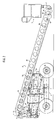
- the vehicular low profile self propelled aerial work platform of the present invention comprises a superstructure support frame 1, having a counterweight 2, mounted on a turntable 3 carried by a vehicle chassis 4.
- a pair of substantially parallel tubular arms 5, 6 are each pivotally connected at one end to the support frame as at 7 and 8, and at the opposite end to a riser frame assembly 9, as at 10 and 11.
- a telescopic boom assembly 12, having a work platform 13 mounted on its outermost end, is pivotally connected to the riser frame assembly as at 14.
- a lower lift cylinder 15 is connected between the support frame 1 and the tubular arm 5 as at 16 and 17, respectively, whereby the tubular arms 5 and 6 and riser frame 9 may be raised and lowered with respect to the vehicle.
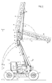
- a boom lift cylinder 18 is similarly connected between the riser frame assembly as at 19 and the base section of the telescopic boom assembly 12 as at 20, whereby the telescopic boom assembly can be raised and lowered with respect to the riser frame assembly 9, as shown in Figures 1, 2 and 3.
- the details of the construction of the machine of the present invention are illustrated in Figures 3, 4 and 5 wherein it will be seen that, to obtain the low profile feature, the turntable 3 is positioned in a horizontal plane in close proximity to the plane of the vehicle axles 21.
- the superstructure support frame 1 comprises a pair of closely spaced side walls 22, 23 secured to the turntable 3 and having a front end wall 24 and a pair of outwardly extending transverse rear walls 25 and 26.
- the detachable counterweight 2 is hooked as at 27 and 28 to the rear walls 25 and 26 and bolted in place as at 29 and 30.
- the counterweight 2 is also provided with lift pins 31 whereby a crane can lift the weight for connecting it to the superstructure support frame.
- the parallel arms 5 and 6 are of tubular or box construction in cross section and are positioned in the space between the superstructure side walls 22 and 23, the pivotal connections 7 and 8 being vertically aligned as shown in Figure 3.
- the space between the side walls 22 and 23 provides a trough 32 aligned with the centerline of the vehicle chassis 4 and aligned with a similar trough 33 provided in the counterweight 2.
- the parallel arms 5 and 6 are aligned with the centerline of the vehicle chassis and are received within the troughs when the machine is lowered, as shown in Figure 2.
- This arrangement also contributes to the low profile feature of the machine, which has a height of approximately eight and a half feet when positioned as shown in Figure 2.
- Machines with lower maximum work platform heights will have a lower overall height. While in the lowered position, as shown in Figure 2, the parallel arms 5 and 6 are slightly inclined in a direction toward the rear of the vehicle, although they are in substantially horizontal planes, and thus are initially oriented or positioned to move in a lifting mode as soon as the lift cylinder 15 is actuated as shown in Figure 3.
- arms 5 and 6 are of tubular construction, as will be seen in Figure 4, a portion of the top and bottom walls of lower arm 6 are cut-away to form openings 34 and 35, respectively, to accommodate the lift cylinder 15 and associated piston rod during the raising and lowering of the arms.
- the riser frame assembly 9 is configured as a channel member having a pair of spaced, parallel side walls 36 and 37 interconnected by a web member 38. Reinforcing plates 39 and 40 are provided on the side walls 36 and 37 at the pivotal connections 10 and 11 of the arms 5 and 6.
- the telescopic boom assembly 12 is provided with an elevated pivot connection 14, on the order of fifteen feet above the ground, so that the boom 12 can extend over an obstruction 41 when the boom is horizontally oriented.
- This type of machine is sometimes referred to as an up and over machine.
- the riser frame assembly 9 always remains vertically oriented in all positions of orientation of the machine.
- the elevated pivot connection 14 also allows for the telescopic boom assembly 12 and associated work platform 13 to be luffed and extended to a position shown in phantom in Figure 1, wherein the work platform 13 extends approximately sixty feet above the ground.
- the telescopic boom assembly comprises a base section 42 and a telescopic boom section 43, the base section containing a fluid cylinder 44 fixed to the inner end of the base section as at 45 and having a piston rod 46 extending into the telescopic section 43 and fixed thereto as at 47.
- a master cylinder 48 is connected between the riser frame assembly 9 and the inner end of the base section 12, the master cylinder 48 being in fluid communication with a slave cylinder 49 mounted on the outer end of the telescopic boom section 43 and connected to the work platform 13 whereby the work platform 13 is maintained in a horizontal position during the luffing of the telescopic boom assembly 12, as well known in the art.
- the base boom section 42 also contains a carrier track assembly 50 for supporting various power cables and hoses extending through the telescopic boom assembly to the conventional controls mounted on the work platform 13, whereby the worker on the platform can control the maneuvering of the vehicle as well as the sluing and luffing of the telescopic boom assembly.
- the structure is completely symmetrical since the telescopic boom assembly 12, boom lift cylinder 18, the pair of parallel arms 5 and 6 and the lower lift cylinder 15 are all positioned in the same vertical plane aligned with the centerline of rotation of turntable 3, and aligned with the centerline of the vehicle chassis in the lowered position of the machine, so that a load on the work platform 13 and the weight of machine components do not transmit any torque to the turntable, as is the case in most prior art machines of this same general type.
Landscapes
- Engineering & Computer Science (AREA)
- Structural Engineering (AREA)
- Mechanical Engineering (AREA)
- Life Sciences & Earth Sciences (AREA)
- Geology (AREA)
- Transportation (AREA)
- Forklifts And Lifting Vehicles (AREA)
Claims (17)
- Plate-forme de travail en hauteur sur véhicule automoteur à profil bas comprenant un châssis de véhicule (4), un plateau tournant (3) monté sur ledit châssis de véhicule (4) et disposé dans un plan horizontal au voisinage immédiat des essieux (21) du véhicule, un châssis de support de superstructure (1) monté sur ledit plateau tournant (3), une paire de bras sensiblement parallèles (5, 6), chaque bras (5, 6) ayant une extrémité reliée de façon pivotante (7, 8) audit cadre de support de superstructure (1), un ensemble à cadre élévateur (9), l'extrémité opposée de chaque bras (5, 6) étant reliée de façon pivotante (10, 11) audit ensemble élévateur (9), un premier cylindre de soulèvement (15) ayant une extrémité reliée de façon pivotante (16) au cadre de support de superstructure (1), l'extrémité opposée dudit premier cylindre de soulèvement (15) étant reliée de façon fonctionnelle (17) à l'un (5) desdits bras, un ensemble à flèche télescopique (12) et une plate-forme de travail associée (13) reliés de façon pivotante (14) audit ensemble élévateur (9), un second cylindre de soulèvement (18) relié fonctionnellement (19, 20) entre ledit ensemble à cadre élévateur (9) et ledit ensemble à flèche télescopique (12) pour soulever ledit ensemble à flèche (12), le bras de support de superstructure (1), les bras parallèles (5, 6) et l'ensemble à cadre élévateur (9) formant un ensemble articulé en parallélogramme, de telle sorte que lors de l'actionnement dudit premier cylindre de soulèvement (15), les bras parallèles (5, 6) et l'ensemble à cadre élévateur (9) se déplacent dans un plan vertical, caractérisée par le fait que ledit cadre de support de superstructure (1) comporte une paire de parois latérales étroitement espacées (22, 23), définissant ainsi deux plans étroitement espacés, un contre-poids (2) relié à une extrémité du cadre de support de superstructure (1) et disposé transversalement par rapport auxdits plans étroitement espacés, un évidement (33) formé dans ledit contre-poids (2), ledit évidement (33) étant aligné avec et formant un prolongement de l'espace (32) entre lesdits plans étroitement espacés, de telle sorte que les bras parallèles (5, 6) se prolongent entre lesdits plans étroitement espacés de la superstructure et le contrepoids, lorsque les premier et second (18) cylindres de soulèvement sont rétractés pour déplacer l'ensemble à cadre élévateur (9) et l'ensemble à flèche télescopique (12) jusqu'à la position la plus basse à laquelle l'ensemble à flèche (12) est abaissé à un angle négatif et le premier cylindre de soulèvement (15) est placé dans l'espace séparant lesdits plans étroitement espacés, de telle sorte que le véhicule et l'ensemble à flèche associé (12) puissent être manoeuvrés aisément au travers de portes et d'allées étroites et basses dans des entrepôts et des installations de fabrication.
- Plate-forme de travail en hauteur sur véhicule automoteur à profil bas selon la revendication 1, dans laquelle le cadre de support de superstructure (1), les bras parallèles (5, 6), l'ensemble à cadre élévateur (9) et l'ensemble à flèche télescopique (12) sont réalisés et agencés symétriquement par rapport à l'axe central de la machine, de telle sorte que les contraintes de charge soient également réparties entre la flèche télescopique (12) et l'ensemble élévateur (9), par l'intermédiaire des bras (5, 6) et des parois latérales (22, 23) de la superstructure.
- Plate-forme de travail en hauteur sur véhicule automoteur à profil bas selon la revendication 1, dans laquelle, lorsque la machine est en position surélevée, l'ensemble à cadre élévateur (9), les bras parallèles (5, 6), le cadre de support de superstructure (1) et le contre-poids (2) sont tous disposés à l'intérieur de l'empâtement du véhicule, ce qui assure un balancement nul de l'arrière du véhicule.
- Plate-forme de travail en hauteur sur véhicule automoteur à profil bas selon la revendication 1, dans laquelle les bras (5, 6) sont de structure tubulaire et sont disposés sensiblement dans un plan vertical l'un par rapport à l'autre.
- Plate-forme de travail en hauteur sur véhicule automoteur à profil bas selon la revendication 4, dans laquelle le premier cylindre de soulèvement (15) est relié fonctionnellement au bras supérieur (5).
- Plate-forme de travail en hauteur sur véhicule automoteur à profil bas selon la revendication 5, dans laquelle des parties des parois supérieure et inférieure du bras inférieur (6) sont découpées de façon à former des ouvertures (34, 35) pour loger le premier cylindre de soulèvement (15) lors de l'élévation et de l'abaissement des bras (5, 6).
- Plate-forme de travail en hauteur sur véhicule automoteur à profil bas selon la revendication 4, dans laquelle le raccord pivotant (7, 8) des bras (5, 6) des parois latérales (22, 23) du cadre de support de superstructure (1) sont verticalement alignés, et positionnés sous ledit ensemble à flèche télescopique (12) lorsqu'elle est dans la position angulaire négative.
- Plate-forme de travail en hauteur sur véhicule automoteur à profil bas selon la revendication 7, dans laquelle les bras parallèles (5, 6) sont légèrement inclinés lorsqu'ils sont en position abaissée afin d'être positionnés dans un mode de soulèvement dès que le premier cylindre de soulèvement (15) est actionné.
- Plate-forme de travail en hauteur sur véhicule automoteur à profil bas selon la revendication 1, dans laquelle les bras (5, 6) et l'ensemble à cadre élévateur (9) sont réalisés et agencés pour former un raccord pivotant surélevé (14) pour l'ensemble à flèche télescopique (12), ce par quoi le raccord pivotant de flèche (14) se situe à environ 2,4 mètres au-dessus du sol lorsque l'ensemble à cadre élévateur (9) est abaissé pour amener l'ensemble à flèche (12) à la position angulaire négative, et se situe à environ 4,5 mètres audessus du sol lorsque l'ensemble à cadre élévateur (9) est amené à la position surélevée.
- Plate-forme de travail en hauteur sur véhicule automoteur à profil bas selon la revendication 8, dans laquelle les bras parallèles (5, 6) et l'ensemble à flèche télescopique (12) sont inclinés dans la même direction, vers l'avant du véhicule, lorsque ledit ensemble à flèche télescopique (12) se trouve dans la position angulaire négative.
- Plate-forme de travail en hauteur sur véhicule automoteur à profil bas selon la revendication 1, dans laquelle la paire de bras parallèles (5, 6), le premier cylindre de soulèvement (15), l'ensemble à cadre élévateur (9), le second cylindre de soulèvement (18), et l'ensemble à flèche télescopique (12) sont positionnés symétriquement dans un plan vertical commun.
- Plate-forme de travail en hauteur sur véhicule automoteur à profil bas selon la revendication 11, dans laquelle ledit ensemble flèche télescopique (12), ledit second cylindre de soulèvement (18) et ladite paire de bras parallèles (5, 6) sont respectivement positionnés l'un au-dessus de l'autre lorsqu'ils sont en position abaissée.
- Plate-forme de travail en hauteur sur véhicule automoteur à profil bas selon la revendication 2, dans laquelle ledit plateau tournant (3) présente un axe central de rotation sur ledit châssis de véhicule (4), et les raccords pivotants (7, 8) des bras (5, 6) sur les parois latérales (22, 23) du cadre de support de superstructure (1), se trouvent du même côté de l'axe de rotation du plateau tournant que la plate-forme de travail (13), à l'extrémité de l'ensemble à flèche télescopique (12).
- Plate-forme de travail en hauteur sur véhicule automoteur à profit bas selon la revendication 2, dans laquelle les raccords pivotant (10, 11) des bras (5, 6) sur ledit ensemble à cadre élévateur (9) sont verticalement alignés, et dans lequel le raccord pivotant (14) dudit ensemble à flèche télescopique (12) sur ledit ensemble élévateur (9) est positionné audessus des raccords pivotants (10, 11) des bras (5, 6) sur ledit ensemble à cadre élévateur (9), et aligné avec ceux-ci.
- Plate-forme de travail en hauteur sur véhicule automoteur à profil bas selon la revendication 2 ou 14, dans laquelle ledit second cylindre de soulèvement (18) est raccordé de façon pivotante (19) audit ensemble à cadre élévateur (9) en une position située entre les raccords pivotants (10, 11) des bras (5, 6) et le raccord pivotant (14) dudit ensemble à flèche télescopique (12) sur ledit ensemble élévateur (9).
- Plate-forme de travail en hauteur sur véhicule automoteur à profil bas selon la revendication 1, dans laquelle les deux bras sensiblement parallèles (5, 6) sont positionnés dans des plans sensiblement horizontaux au-dessus et au voisinage immédiat du plan dudit plateau tournant (3), et dans laquelle ledit second cylindre de soulèvement (18) est disposé dans un plan sensiblement horizontal au-dessus et à proximité immédiate des plans horizontaux desdits bras (5, 6) lorsque la machine est en position rétractée et lorsque l'ensemble à flèche télescopique (12) est en position angulaire négative.
- Plate-forme de travail en hauteur sur véhicule automoteur à profil bas selon la revendication 16, dans laquelle le raccord pivotant (14) de l'ensemble à flèche télescopique (12) sur ledit ensemble à cadre élévateur (9) est positionné au-dessus du raccord pivotant (19) dudit second cylindre de soulèvement (18) sur ledit ensemble à cadre élévateur (9) et se trouve en alignement vertical avec les raccords pivotants (10, 11) des bras (5, 6) sur ledit ensemble à cadre élévateur (9).
Applications Claiming Priority (2)
| Application Number | Priority Date | Filing Date | Title |
|---|---|---|---|
| US07/101,016 US4757875A (en) | 1987-09-25 | 1987-09-25 | Vehicular low profile self propelled aerial work platform |
| US101016 | 1987-09-25 |
Publications (2)
| Publication Number | Publication Date |
|---|---|
| EP0308595A1 EP0308595A1 (fr) | 1989-03-29 |
| EP0308595B1 true EP0308595B1 (fr) | 1992-06-03 |
Family
ID=22282684
Family Applications (1)
| Application Number | Title | Priority Date | Filing Date |
|---|---|---|---|
| EP88111045A Expired - Lifetime EP0308595B1 (fr) | 1987-09-25 | 1988-07-11 | Plate-forme pour travail en hauteur sur véhicule automoteur, à profil bas |
Country Status (9)
| Country | Link |
|---|---|
| US (1) | US4757875A (fr) |
| EP (1) | EP0308595B1 (fr) |
| JP (1) | JPH0639319B2 (fr) |
| KR (1) | KR910008173B1 (fr) |
| AU (1) | AU593205B2 (fr) |
| DE (1) | DE3871683T2 (fr) |
| ES (1) | ES2031961T3 (fr) |
| FI (1) | FI88792C (fr) |
| MX (1) | MX163936B (fr) |
Families Citing this family (21)
| Publication number | Priority date | Publication date | Assignee | Title |
|---|---|---|---|---|
| US4858723A (en) * | 1988-07-29 | 1989-08-22 | Hi-Ranger, Inc. | Bucket leveling system |
| BE1003344A4 (fr) * | 1990-01-24 | 1992-03-03 | Manitou Bf Sa | Chariot elevateur a bras telescopique. |
| US5249643A (en) * | 1992-04-03 | 1993-10-05 | Kidde Industries, Inc. | Vehicular self-propelled aerial work platform and telescoping parallelogram boom therefor |
| FR2702752B1 (fr) * | 1993-03-17 | 1995-05-05 | Hiviaco 88 | Dispositif élévateur pour nacelle de transport de personnes. |
| US5460246A (en) * | 1993-08-23 | 1995-10-24 | O'flaherty Finance | Articulated aerial lift |
| US5355970A (en) * | 1993-08-26 | 1994-10-18 | Kidde Industries, Inc. | Multicell articulated riser system for a self propelled aerial work platform |
| US5584356A (en) * | 1995-05-31 | 1996-12-17 | Kidde Industries, Inc. | Centerline double riser with single lift cylinder and link for a low profile self propelled aerial work platform |
| US5743149A (en) * | 1996-02-26 | 1998-04-28 | Skyjack Equipment Inc. | Articulated telescopic boom having slide-through knuckle |
| CA2177508C (fr) * | 1996-05-28 | 2001-03-20 | George Leslie Lawson | Elevateur mobile |
| US6170606B1 (en) | 1996-06-28 | 2001-01-09 | Safety Dynamicon, Inc. | Analog control |
| CA2227986C (fr) * | 1997-01-31 | 2004-12-28 | Kidde Industries, Inc. | Appareil de levage muni d'un ensemble articule de double fleche sous forme de parallelogramme |
| FR2774083B1 (fr) | 1998-01-27 | 2000-04-07 | Kidde Ind Inc | Dispositif elevateur perfectionne |
| US6217044B1 (en) | 1999-04-15 | 2001-04-17 | Beeche Systems, Corp. | Steerable and retractable wheels for multi-purpose carriage |
| US6341665B1 (en) | 1999-09-13 | 2002-01-29 | Grove U.S. L.L.C. | Retractable counterweight for straight-boom aerial work platform |
| KR20010085129A (ko) * | 2000-02-28 | 2001-09-07 | 양철 | 폐자원을 이용한 재생제품의 제조방법 |
| US6488161B1 (en) | 2000-05-02 | 2002-12-03 | Jlg Industries, Inc. | Boom mechanism |
| US7963695B2 (en) * | 2002-07-23 | 2011-06-21 | Rapiscan Systems, Inc. | Rotatable boom cargo scanning system |
| DE202004011990U1 (de) | 2004-07-30 | 2005-12-08 | Liebherr-Hydraulikbagger Gmbh | Umschlaggerät |
| US8631902B2 (en) * | 2009-01-08 | 2014-01-21 | California Manufacturing & Engineering Co. | Apparatus for elevating and positioning a work platform |
| ITUB20155900A1 (it) * | 2015-11-25 | 2017-05-25 | Magni Telescopic Handlers S R L | Piattaforma aerea semovente |
| CN108561626B (zh) * | 2018-05-24 | 2023-11-28 | 张跃 | 一种管道安装装置及方法 |
Family Cites Families (14)
| Publication number | Priority date | Publication date | Assignee | Title |
|---|---|---|---|---|
| US2996141A (en) * | 1959-05-08 | 1961-08-15 | Jay M Eitel | Mobile lifting equipment |
| US3103345A (en) * | 1960-12-08 | 1963-09-10 | Telsta Corp | Cable guiding device |
| US3448827A (en) * | 1967-08-16 | 1969-06-10 | Clark Arthur D | Mobile worker support |
| US3483948A (en) * | 1967-11-03 | 1969-12-16 | Walter E Thornton Trump | Elevator-boom structure |
| US3575262A (en) * | 1968-12-27 | 1971-04-20 | Transairco Inc | Aerial lift apparatus with elevator |
| US3836025A (en) * | 1973-05-21 | 1974-09-17 | Loed Corp | Material-handling machine |
| US3856108A (en) * | 1973-05-25 | 1974-12-24 | Fulton Industries | Three wheel aerial platform apparatus |
| GB1412558A (en) * | 1973-06-27 | 1975-11-05 | Simon Eng Dudley Ltd | Access equipment |
| US3861498A (en) * | 1973-07-13 | 1975-01-21 | Fulton Industries | Counterbalancing chassis for aerial platform apparatus |
| US4000787A (en) * | 1974-09-16 | 1977-01-04 | Groenig Robert E | Vehicle for picking fruit |
| US4273214A (en) * | 1977-02-28 | 1981-06-16 | Jlg Industries, Inc. | Track mounted aerial lift platform apparatus |
| US4160492A (en) * | 1977-10-06 | 1979-07-10 | Simon-Krause, Inc. | Control system for mobile self-propelled aerial lift |
| US4226300A (en) * | 1979-02-21 | 1980-10-07 | Mark Industries | Self propelled and extensible boom lift |
| US4280589A (en) * | 1980-01-31 | 1981-07-28 | Merrick John A | Elevating device |
-
1987
- 1987-09-25 US US07/101,016 patent/US4757875A/en not_active Expired - Lifetime
-
1988
- 1988-07-11 ES ES198888111045T patent/ES2031961T3/es not_active Expired - Lifetime
- 1988-07-11 DE DE8888111045T patent/DE3871683T2/de not_active Expired - Lifetime
- 1988-07-11 EP EP88111045A patent/EP0308595B1/fr not_active Expired - Lifetime
- 1988-07-13 FI FI883327A patent/FI88792C/fi not_active IP Right Cessation
- 1988-07-15 AU AU19085/88A patent/AU593205B2/en not_active Ceased
- 1988-07-18 KR KR1019880008978A patent/KR910008173B1/ko not_active IP Right Cessation
- 1988-07-18 JP JP63177287A patent/JPH0639319B2/ja not_active Expired - Lifetime
- 1988-07-18 MX MX12303A patent/MX163936B/es unknown
Also Published As
| Publication number | Publication date |
|---|---|
| KR890004906A (ko) | 1989-05-10 |
| FI883327A (fi) | 1989-03-26 |
| FI88792B (fi) | 1993-03-31 |
| EP0308595A1 (fr) | 1989-03-29 |
| AU1908588A (en) | 1989-04-06 |
| AU593205B2 (en) | 1990-02-01 |
| JPH0198599A (ja) | 1989-04-17 |
| DE3871683D1 (de) | 1992-07-09 |
| DE3871683T2 (de) | 1992-12-17 |
| JPH0639319B2 (ja) | 1994-05-25 |
| FI88792C (fi) | 1993-07-12 |
| KR910008173B1 (ko) | 1991-10-10 |
| MX163936B (es) | 1992-07-02 |
| ES2031961T3 (es) | 1993-01-01 |
| FI883327A0 (fi) | 1988-07-13 |
| US4757875A (en) | 1988-07-19 |
Similar Documents
| Publication | Publication Date | Title |
|---|---|---|
| EP0308595B1 (fr) | Plate-forme pour travail en hauteur sur véhicule automoteur, à profil bas | |
| CA2476573C (fr) | Assemblage de mat de chariot elevateur | |
| CA2177344C (fr) | Plate-forme de travail aerienne, auto-propulsee et a profil bas | |
| USRE30021E (en) | Material handling machine | |
| US4674944A (en) | Forklift variable reach mechanism | |
| US3967744A (en) | Extensible reach load lifting mechanism | |
| JPH0361296A (ja) | フオークリフトトラツク | |
| US20040256344A1 (en) | Traveling crane | |
| US3802589A (en) | Dual extensible reach truck | |
| EP0931759A1 (fr) | Flèche latérale pour plateforme de travail mobile à mât vertical | |
| JPH01117199A (ja) | 伸縮可能なブーム機械用キヤリヤトラツク集合体 | |
| US4374550A (en) | Upright for lift truck | |
| US3198359A (en) | Reaching type loader | |
| CA1292957C (fr) | Plate-forme elevatrice autopropulsee et surbaissee pour travaux en hauteur | |
| CA1097266A (fr) | Guide-mat de chariot elevateur | |
| CN112682076A (zh) | 一种隧道拱架施工作业车 | |
| US20020006325A1 (en) | High visibility rough terrain forklift with tight turning radius and extensible boom | |
| CN214366118U (zh) | 一种隧道拱架施工作业车 | |
| CA1105892A (fr) | Timonerie | |
| GB2253830A (en) | Material handling vehicle | |
| WO1999008954A1 (fr) | Porte-bobines | |
| JPH0224339Y2 (fr) | ||
| JPH0139637Y2 (fr) |
Legal Events
| Date | Code | Title | Description |
|---|---|---|---|
| PUAI | Public reference made under article 153(3) epc to a published international application that has entered the european phase |
Free format text: ORIGINAL CODE: 0009012 |
|
| AK | Designated contracting states |
Kind code of ref document: A1 Designated state(s): CH DE ES FR GB IT LI NL SE |
|
| 17P | Request for examination filed |
Effective date: 19890831 |
|
| 17Q | First examination report despatched |
Effective date: 19901128 |
|
| ITF | It: translation for a ep patent filed |
Owner name: STUDIO INGG. FISCHETTI & WEBER |
|
| GRAA | (expected) grant |
Free format text: ORIGINAL CODE: 0009210 |
|
| AK | Designated contracting states |
Kind code of ref document: B1 Designated state(s): CH DE ES FR GB IT LI NL SE |
|
| RIN1 | Information on inventor provided before grant (corrected) |
Inventor name: BACKER, ROBERT D. Inventor name: HADE, DONALD C. JR. |
|
| REF | Corresponds to: |
Ref document number: 3871683 Country of ref document: DE Date of ref document: 19920709 |
|
| ET | Fr: translation filed | ||
| REG | Reference to a national code |
Ref country code: ES Ref legal event code: FG2A Ref document number: 2031961 Country of ref document: ES Kind code of ref document: T3 |
|
| PLBE | No opposition filed within time limit |
Free format text: ORIGINAL CODE: 0009261 |
|
| STAA | Information on the status of an ep patent application or granted ep patent |
Free format text: STATUS: NO OPPOSITION FILED WITHIN TIME LIMIT |
|
| 26N | No opposition filed | ||
| EAL | Se: european patent in force in sweden |
Ref document number: 88111045.6 |
|
| REG | Reference to a national code |
Ref country code: CH Ref legal event code: PUE Owner name: KIDDE INDUSTRIES INC. TRANSFER- GROVE U.S. LLC |
|
| REG | Reference to a national code |
Ref country code: ES Ref legal event code: PC2A |
|
| REG | Reference to a national code |
Ref country code: FR Ref legal event code: TP |
|
| NLS | Nl: assignments of ep-patents |
Owner name: GROVE U.S. LLC |
|
| PGFP | Annual fee paid to national office [announced via postgrant information from national office to epo] |
Ref country code: ES Payment date: 20000511 Year of fee payment: 13 |
|
| PGFP | Annual fee paid to national office [announced via postgrant information from national office to epo] |
Ref country code: GB Payment date: 20000522 Year of fee payment: 13 |
|
| PGFP | Annual fee paid to national office [announced via postgrant information from national office to epo] |
Ref country code: SE Payment date: 20000717 Year of fee payment: 13 |
|
| PGFP | Annual fee paid to national office [announced via postgrant information from national office to epo] |
Ref country code: FR Payment date: 20000721 Year of fee payment: 13 |
|
| PGFP | Annual fee paid to national office [announced via postgrant information from national office to epo] |
Ref country code: CH Payment date: 20000726 Year of fee payment: 13 |
|
| PGFP | Annual fee paid to national office [announced via postgrant information from national office to epo] |
Ref country code: NL Payment date: 20000731 Year of fee payment: 13 |
|
| PG25 | Lapsed in a contracting state [announced via postgrant information from national office to epo] |
Ref country code: GB Free format text: LAPSE BECAUSE OF NON-PAYMENT OF DUE FEES Effective date: 20010711 |
|
| PG25 | Lapsed in a contracting state [announced via postgrant information from national office to epo] |
Ref country code: SE Free format text: LAPSE BECAUSE OF NON-PAYMENT OF DUE FEES Effective date: 20010712 Ref country code: ES Free format text: LAPSE BECAUSE OF NON-PAYMENT OF DUE FEES Effective date: 20010712 |
|
| PG25 | Lapsed in a contracting state [announced via postgrant information from national office to epo] |
Ref country code: LI Free format text: LAPSE BECAUSE OF NON-PAYMENT OF DUE FEES Effective date: 20010731 Ref country code: CH Free format text: LAPSE BECAUSE OF NON-PAYMENT OF DUE FEES Effective date: 20010731 |
|
| PGFP | Annual fee paid to national office [announced via postgrant information from national office to epo] |
Ref country code: DE Payment date: 20010831 Year of fee payment: 14 |
|
| PG25 | Lapsed in a contracting state [announced via postgrant information from national office to epo] |
Ref country code: NL Free format text: LAPSE BECAUSE OF NON-PAYMENT OF DUE FEES Effective date: 20020201 |
|
| EUG | Se: european patent has lapsed |
Ref document number: 88111045.6 |
|
| GBPC | Gb: european patent ceased through non-payment of renewal fee |
Effective date: 20010711 |
|
| REG | Reference to a national code |
Ref country code: CH Ref legal event code: PL |
|
| PG25 | Lapsed in a contracting state [announced via postgrant information from national office to epo] |
Ref country code: FR Free format text: LAPSE BECAUSE OF NON-PAYMENT OF DUE FEES Effective date: 20020329 |
|
| NLV4 | Nl: lapsed or anulled due to non-payment of the annual fee |
Effective date: 20020201 |
|
| REG | Reference to a national code |
Ref country code: FR Ref legal event code: ST |
|
| PG25 | Lapsed in a contracting state [announced via postgrant information from national office to epo] |
Ref country code: DE Free format text: LAPSE BECAUSE OF NON-PAYMENT OF DUE FEES Effective date: 20030201 |
|
| REG | Reference to a national code |
Ref country code: ES Ref legal event code: FD2A Effective date: 20020810 |
|
| PG25 | Lapsed in a contracting state [announced via postgrant information from national office to epo] |
Ref country code: IT Free format text: LAPSE BECAUSE OF NON-PAYMENT OF DUE FEES Effective date: 20050711 |