EP0308315B1 - Interpolationsverfahren - Google Patents
Interpolationsverfahren Download PDFInfo
- Publication number
- EP0308315B1 EP0308315B1 EP88402299A EP88402299A EP0308315B1 EP 0308315 B1 EP0308315 B1 EP 0308315B1 EP 88402299 A EP88402299 A EP 88402299A EP 88402299 A EP88402299 A EP 88402299A EP 0308315 B1 EP0308315 B1 EP 0308315B1
- Authority
- EP
- European Patent Office
- Prior art keywords
- image
- interpolation
- mesh
- memory
- coordinates
- Prior art date
- Legal status (The legal status is an assumption and is not a legal conclusion. Google has not performed a legal analysis and makes no representation as to the accuracy of the status listed.)
- Expired - Lifetime
Links
Images
Classifications
-
- G—PHYSICS
- G06—COMPUTING OR CALCULATING; COUNTING
- G06T—IMAGE DATA PROCESSING OR GENERATION, IN GENERAL
- G06T3/00—Geometric image transformations in the plane of the image
- G06T3/40—Scaling of whole images or parts thereof, e.g. expanding or contracting
- G06T3/4007—Scaling of whole images or parts thereof, e.g. expanding or contracting based on interpolation, e.g. bilinear interpolation
-
- G—PHYSICS
- G06—COMPUTING OR CALCULATING; COUNTING
- G06T—IMAGE DATA PROCESSING OR GENERATION, IN GENERAL
- G06T5/00—Image enhancement or restoration
- G06T5/80—Geometric correction
-
- A—HUMAN NECESSITIES
- A61—MEDICAL OR VETERINARY SCIENCE; HYGIENE
- A61B—DIAGNOSIS; SURGERY; IDENTIFICATION
- A61B6/00—Apparatus or devices for radiation diagnosis; Apparatus or devices for radiation diagnosis combined with radiation therapy equipment
- A61B6/42—Arrangements for detecting radiation specially adapted for radiation diagnosis
- A61B6/4208—Arrangements for detecting radiation specially adapted for radiation diagnosis characterised by using a particular type of detector
- A61B6/4258—Arrangements for detecting radiation specially adapted for radiation diagnosis characterised by using a particular type of detector for detecting non x-ray radiation, e.g. gamma radiation
Definitions
- the present invention relates to a method of interpolating the value of a point in a mesh with N vertices.
- the interpolation studied is preferably of the bilinear type, although the invention applies to cases where it is neither linear nor even double but rather multiple.
- the mesh has four vertices, but in certain applications, in particular in imaging applications representing three-dimensional objects, the mesh could have a different number of vertices: for example three, six or eight vertices. .
- the interpolation method of the invention finds an application in the medical field where it can be used to correct distortions of images acquired with gamma cameras.
- the main interest of the interpolation method of the invention lies in the speed with which the interpolation can be done. This speed allows processing in real time while respecting the usual standards for video and television representation for viewing images.
- Gamma cameras are used in nuclear medicine to visualize in an organ the distribution of molecules marked by a radioactive isotope that has been injected into a patient.
- a gamma camera generally includes a collimator to focus the gamma-ray photons emitted by the patient, a scintillator crystal to transform gamma photons into light photons or scintillations, and a network of photo-multiplier tubes which transform each of the scintillations into electrical pulses called electrical contributions from tubes.
- They also include electronic circuits to produce from the electrical contributions provided by the photo-multiplier tubes, signals of coordinates X and Y of the place where a scintillation occurred, as well as a validation signal Z when the W energy of the scintillation belongs to a predetermined energy band.
- This detection chain is generally followed by a display assembly which may include a cathode oscilloscope controlled by the signals of coordinates X, Y, and by Z to visualize by a luminous point on the screen the point of impact of the gamma photon. on the crystal. This impact is also called an image event.
- the display assembly may optionally include a photographic device for forming an image of the organ observed by integrating a large number of light points produced on the cathode-ray screen. It can also include digital image processing.
- the display assembly can be adapted to the representation of tomographies of the organ observed. To achieve this goal, several images of this organ are acquired according to a plurality of observation orientations of the gamma-camera with respect to this organ. By signal processing, analogous to those encountered in CT scanners, images of sections of the organs examined can be reconstructed.
- a gamma camera must have a good spatial resolution, that is to say the ability to distinguish from small close-up radioactive sources, a good response in counting rate, that is to say the ability to process a large number of 'events per unit of time, and image quality as independent as possible from the energy of the isotope under consideration.
- the spatial resolution depends on the precision of the calculations of the X and Y coordinates of each of the image events. The quality of the development of these coordinates depends on the accuracy of the measurements and the physical laws governing the operation of the different parts of the gamma-camera.
- the interaction of a gamma photon with the crystal gives rise to a light scintillation, the intensity of which decreases expotentially over time.
- This scintillation is seen by several photo-multiplier tubes simultaneously.
- the light photons making up this scintillation pull photoelectrons from the photo-cathodes of the photo-multiplier tubes.
- the number of photo-electrons torn off obeys, for a given scintillation, the Poisson statistical law.
- the electrical contribution is a substantially Gaussian function of the distance separating the center of the photo-multiplier tube from the projection of the place where the scintillation occurred. If the scintillation occurs directly above the center of the tube, the electrical contribution is maximum. The further the scintillation site is from the center of the tube, the lower the electrical contribution. For example, if a scintillation occurs directly above the wall of the tube, the electrical contribution of the latter is approximately halved compared to the maximum electrical contribution.
- a scintillation is seen by several photo-multiplier tubes simultaneously, generally 6 to 10 tubes. Also, the determination of the location of this scintillation on the crystal, itself representative of the place of emission of the excitation gamma photon (and therefore of the image event), can be obtained by calculating the location of the barycenter of the electrical contributions delivered by all the photo-multiplier tubes excited by this scintillation. This calculation is carried out simply, according to the American patent ANGER No. 3011057, by injecting the electrical contributions through a set of resistance matrices whose resistance values are a function of the positions of the photo-multiplier tubes to which they are connected.
- each matrix there are as many resistors as there are photo-multiplier tubes in the network of tubes.
- Each of the resistors is connected on the one hand to the output of a different photo-multiplier tube and on the other hand to a common point which constitutes the output of the matrix.
- One of the problems presented by the ANGER type gamma cameras is that they present geometric distortions of the image linked to the light capture structure: scintillator crystal-photomultiplier tube-barycentration matrix.
- a computer develops a correction matrix of 64 X 64 new U and V coordinates of an undistorted image corresponding to the same number of X and Y coordinates of l distorted image of the target.
- the acquired X and Y coordinates of the image events are coded on 12 bits.
- the 6 most significant bits of X and Y address the memory of U and V.
- a linear interpolation is carried out using the 6 least significant bits of X and Y.
- Given an image field of approximately 400 mm diameter, a 12-bit coding of the coordinates of the image events should normally lead to an image definition of the order of 0.1 mm.
- the acquired coordinates of the image events are given on 12 bits, there remain 5 bits to make an interpolation of the true position of an image event in the mesh corrected to which we just determined it must belong.
- a first correction CI is calculated from the coordinates x (or respectively y) and corrections of coordinates of the two vertices of the mesh: DXa (or DYa) and DXb (or DYb).
- DXa or DYa
- DXb or DYb
- Another computation CJ is then calculated by interpolation between the other two vertices C and D of the mesh.
- CJx or CJy
- the final computation consists, starting from CI and CJ to obtain displacement DX (or DY).
- any image correction method based ultimately on such a direct addressing technique requires exorbitant memory capacity.
- a memory of 16 Mega words of 24 bits (12 bits to determine X corrected, and 12 bits to determine Y corrected) would be required. This memory would be addressed by the X and Y acquired and coded each on 12 bits. This capacity exceeds the technological limits currently available.
- a patent application GB-A-2 026 811 describes a method and a machine for reproducing a color image, a light brush scanning the original image.
- the analog image signal thus obtained is separated into n elementary image signals which are then digitalized, one of these signals is then stored, in its entirety, in a memory, while the others are sampled according to regular models, the sampled values being stored in memory.
- the elementary image signals with digital output are obtained in said memory, by reading the first elementary image signal without modification, by reading the others and by performing an interpolation of the stored values.
- the output signals are then used to obtain the desired reproduced image.
- the interpolation is carried out according to the method defined by the preamble of claim 1.
- the object of the invention is to remedy the drawbacks defined above by proposing an interpolation method where the memory capacity is not particularly increased but where on the other hand the interpolation calculation can be done in real time.
- the fact that the interpolation calculation can be done in real time can be used in the video domain. Indeed the representation of movements requires the acquisition and storage of many images. In order not to increase the memory capacities too much At the time of this storage, it may be useful, since we are only interested in movement, to store only degraded definition images. In some cases, in particular in the study of cardiac movements by gamma-camera, the images obtained have a weak definition from the start.
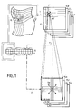
- FIG. 1 schematically represents an interpolation method similar to that used according to the invention.
- a point P or image event, is defined, after an acquisition, by its X and Y coordinates.
- the acquisition is an acquisition obtained following an experiment with a gamma-camera and, to fix ideas, the X and Y coordinates are given in binary form with 12 bits of definition.
- the point P belongs to a distorted image ID which is unusable. To be able to be used, this image must be corrected by an image distortion correction method. Ultimately, it is necessary to calculate the coordinates of a point P 'in a corrected image IC.
- each elementary cell M of the distorted image ID acquired is assigned a corrected cell M ′ whose vertices A, B, C and D are defined by corrections of coordinates, also called here weighting coefficients, DXa - DYa, DXb ... DYd.
- a first step consists in assigning to a mesh M a mesh M '.
- the second step consists in interpolating the position of the point P 'in the mesh M' according to the position of the point P in the mesh M and according to the weighting coefficients of the vertices of the mesh.
- the arrow 1 represents the first operation.
- the most significant bits of the X and Y coordinates are used. In a particular embodiment, the seven most significant bits are used so as to define a mesh of 128 X 128 meshes in the distorted images ID and corrected IC.
- the fineness of interpolation to be obtained is determined.
- the fineness of interpolation to be obtained relates to the five least significant bits, denoted x and y, of the coordinates X and Y.
- Ka is called the contribution (1-x-y + xy)
- Kd the contribution (xy) the invention aims to precalculate the contributions of Ka, Kb, Kc, and Kd, for all the possible values of x and y corresponding to the fineness of interpolation to be obtained. These values are then stored in read only memories called interpolation matrices.
- each x or y coordinate can therefore take 32 values.
- each memory cell has a contribution coded on eight bits.
- the interpolation requires a memory increase of 4 K bytes to store all the relative contributions.
- the correction mesh comprises eight memory zones known as of correction of coordinates and relating to the displacements of the tops of the meshes: DXa, DYa, DXb, ... DYd, of the fact that these corrections of coordinates are coded each on 11 bits (one sign bit, eight significant bits and two fractional bits), and the fact that the correction mesh is relative to a 128 X 128 resolution
- the overall memory size is 2 times 16 K words of 11 bits of RAM , and 4K bytes of ROM.
- the coordinate corrections must be able to change, as a function of the aging of the gamma-camera for example, while the precomputed relative contributions are immutable. They can therefore be stored in a read-only memory.
- the additional memory size for the interpolation matrices is therefore negligible.
- the precalculation of the interpolation contributions can be simplified by using, for programming the memories Ka, Kb and Kc, the results obtained for the precalculation of the memory Kd.
- the multiplication x.y has not been redone.
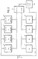
- FIG. 2 represents the preferred method of determining the corrected coordinates of the points P ′ in the mesh M ′.
- a bus 2 routes the X and Y coordinates to the coordinate correction memories 3 to 6 on the one hand, and to the interpolation memories 7 to 10 on the other hand.
- a multiplier-accumulator 15 connected to the outputs of these memories then receives correction memories, the correction of coordinates DX (or DY) on the one hand, and interpolation memories 7 to 10 the relative contributions of interpolation K of somewhere else. It performs the corresponding multiplications and the accumulation of results of these multiplications.
- IL delivers, as appropriate, the displacement DX then the displacement DY. With the accumulator multiplier 15 the processing is carried out in series.
- a correction circuit 150 then delivers the corrected coordinates of the image events by adding the calculated displacements to the distorted coordinates.
- the method of the invention can also make it possible to save more time.
- the addressing of the coordinate corrections of the different vertices of the correction mesh M ′ can be simultaneous.
- X and Y, or at least the 7 most significant bits of X and Y represent the top A of the mesh.
- the vertices B, C and D are deduced therefrom by an addition or a subtraction of a unit of least significant bit among the most significant bits. Consequently, we can have access simultaneously to the 8 weighting coefficients DXa, DYa, etc. At the same time, it is also possible to access the Ka, Kb, Kc and Kd contributions simultaneously.
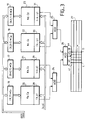
- the video application shown in part in Figure 3 is similar.
- this one a frame of an image available at low resolution.
- it has 64 rows and 64 columns: there are 4 K possible positions for image events and in one example each image element can be coded on 8 bits, ie 256 levels of gray, luminance or chrominance.
- the storage of images is therefore not very demanding.
- the x coordinate coded on 2 bits must be able to be worth from 1 to 4 and the y coordinate also coded on 2 bits must be able to also take the values from 1 to 4. Knowing the gray level, the weighting coefficient, Ca, Cb, Cc and Cd in each of the vertices A, B, C and D of the mesh, it is possible, by a calculation similar to that presented above, to calculate the intermediate gray levels of the intermediate points contained in the mesh.
- low definition source images are read at each cycle time to determine the gray levels, or weighting coefficients, Ca to Cd of the four vertices A to D of a mesh.
- the source memory can be quadrupled so as to be addressed simultaneously in X and Y in order to simultaneously deliver the weighting coefficients Ca to Cd.
- it can be organized differently by separating the even image events in x and y. This different organization then makes it possible to read simultaneously, but in different areas of this memory, the weighting coefficients Ca to Cd of the four vertices of the mesh. If necessary, a multiplexing of reading of this memory can also be organized.
- the memory of the source image or to simplify the explanation the source memories 16 to 19, then deliver the four weighting coefficients on 8 bits each representative of the gray level of one of the vertices of the mesh.
- These gray levels can be used as the address input of each of the memories 20 to 23 of composite precalculation having produced the product KC, and receiving as other address codes corresponding successively to each of the four intermediate positions of the interpolated points 41 to 44 located on the same line in the stitch.
- a line y is fixed, only x varies (from 1 to 4).
- the composite memories 20 to 23 then each deliver successively four results corresponding to the calculation of the luminosity weighted in four places in the mesh according to one of the vertices of this mesh.
- a set of adders 24 to 26 makes it possible to add the results delivered by the four memories 20 to 23 and to deliver the weighted brightness corresponding to this point.
- the four luminosities can be interpolated in 664 nomoseconds.
- the brightnesses in 256 points of a video line can therefore be calculated in 43 microseconds.
- the visualization of the image can then be obtained in conventional video mode. Indeed, in conventional video playback at 25 frames per second, reading a line of an image lasts 64 microseconds.
- the compatibility of these two durations (64 microseconds being greater than 43 microseconds) qualifies the interpolation method thus presented for viewing "on the fly" from weakly defined images to highly defined images.
- the interpolation mode recommended in these two applications is preferably a linear mode. Given the fact that we are trying to represent two-dimensional images, the interpolation mode will even be bilinear. However, the invention can be transposed to an interpolation of a point in a three-dimensional geometric space, or even in a theoretical M-dimensional space. Furthermore, the interpolation is not necessarily of the linear type. Other functions than the linear function are also possible. Being a mesh with N vertices, it may only be necessary that the sum of the contributions relating to each of these vertices is equal to 1.
- N is equal to four as what has just been described.
- the number of vertices can be different. In these latter cases, rather than calculating the contributions according to a Cartesian definition, it may be preferable to use a polar definition.
Landscapes
- Physics & Mathematics (AREA)
- General Physics & Mathematics (AREA)
- Engineering & Computer Science (AREA)
- Theoretical Computer Science (AREA)
- Image Processing (AREA)
- Television Systems (AREA)
- Nuclear Medicine (AREA)
- Complex Calculations (AREA)
Claims (6)
- Multiples Interpolationsverfahren des Wertes eines Punktes P in einem Elementargitter mit wenigstens 4 Spitzen (A, B, C, D) eines aus Pixeln bestehenden Bildes, wobei Gewichtungskoeffizienten (Ca...Cd) diesen Spitzen zugeordnet sind, bei dem:- die Gewichtungskoeffizienten der Pixel des Bildes gespeichert werden in einem Speicher (16-19), der adressiert wird durch die Bits hoher Wertigkeit (X, Y) der Koordinaten X und Y des Punkts P,- die Gewichtungskoeffizienten in diesen Spitzen (A, B, C, D) des Gitters simultan aus diesem Speicher gelesen werden,- die ausgelesenen Gewichtungskoeffizienten mit vorberechneten, in einer Tabelle (20-23) gespeicherten Werten (Ka...Kd) multipliziert werden,- diese vorberechneten Werte Interpolationskontributionen (Ka, Kb, Kc, Kd) bezüglich aller Orte des Gitters (A, B, C, D) sind, für eine bestimmte Interpolationsfeinheit (x, y), vorberechnet gemäß Ka=1-x-y+xy, Kb=x-xy, Kc=y-yx und Kd=xy,- man dem Punkt P als interpolierten Wert das Resultat einer algebraischen Komposition dieser Kontributionen und Gewichtungskoeffizienten der Spitzen des Gitters zuweist,
dadurch gekennzeichnet, daß
- die gespeicherte Tabelle (20-23) als vorberechnete Werte das Produkt der Gewichtungskoeffizienten (Ca...Cd) der Spitzen und ihrer entsprechenden Interpolationskontributionen (Ka...Kd) enthält. - Verfahren nach Anspruch 1, dadurch gekennzeichnet, daß die multiple Interpolation eine doppelte Interpolation (in x und y) ist.
- Verfahren nach Anspruch 2, dadurch gekennzeichnet, daß die doppelte Interpolation eine bilineare Interpolation ist.
- Verfahren nach einem der Ansprüche 1 bis 3, dadurch gekennzeichnet, daß der Wert die Helligkeit oder den Farbton eines Bildelements darstellt.
- Verfahren nach Anspruch 4, dadurch gekennzeichnet, daß man die interpolierten Werte zum Teil auf Grund von vorbestimmten Werten der Gewichtungskoeffizienten vorberechnet (20, 30).
- Verfahren nach einem der Ansprüche 1 bis 5, dadurch gekennzeichnet, daß es angewandt wird bei einem Bild des Videotyps.
Applications Claiming Priority (2)
| Application Number | Priority Date | Filing Date | Title |
|---|---|---|---|
| FR8712814A FR2620544B1 (fr) | 1987-09-16 | 1987-09-16 | Procede d'interpolation |
| FR8712814 | 1987-09-16 |
Publications (2)
| Publication Number | Publication Date |
|---|---|
| EP0308315A1 EP0308315A1 (de) | 1989-03-22 |
| EP0308315B1 true EP0308315B1 (de) | 1993-12-15 |
Family
ID=9354941
Family Applications (1)
| Application Number | Title | Priority Date | Filing Date |
|---|---|---|---|
| EP88402299A Expired - Lifetime EP0308315B1 (de) | 1987-09-16 | 1988-09-13 | Interpolationsverfahren |
Country Status (6)
| Country | Link |
|---|---|
| US (1) | US5048102A (de) |
| EP (1) | EP0308315B1 (de) |
| JP (1) | JPH01126779A (de) |
| DE (1) | DE3886323T2 (de) |
| FR (1) | FR2620544B1 (de) |
| IL (1) | IL87703A0 (de) |
Cited By (8)
| Publication number | Priority date | Publication date | Assignee | Title |
|---|---|---|---|---|
| US8823823B2 (en) | 1997-07-15 | 2014-09-02 | Google Inc. | Portable imaging device with multi-core processor and orientation sensor |
| US8866923B2 (en) | 1999-05-25 | 2014-10-21 | Google Inc. | Modular camera and printer |
| US8896724B2 (en) | 1997-07-15 | 2014-11-25 | Google Inc. | Camera system to facilitate a cascade of imaging effects |
| US8902333B2 (en) | 1997-07-15 | 2014-12-02 | Google Inc. | Image processing method using sensed eye position |
| US8908075B2 (en) | 1997-07-15 | 2014-12-09 | Google Inc. | Image capture and processing integrated circuit for a camera |
| US8908069B2 (en) | 1997-07-15 | 2014-12-09 | Google Inc. | Handheld imaging device with quad-core image processor integrating image sensor interface |
| US8936196B2 (en) | 1997-07-15 | 2015-01-20 | Google Inc. | Camera unit incorporating program script scanner |
| US9055221B2 (en) | 1997-07-15 | 2015-06-09 | Google Inc. | Portable hand-held device for deblurring sensed images |
Families Citing this family (40)
| Publication number | Priority date | Publication date | Assignee | Title |
|---|---|---|---|---|
| JP2957623B2 (ja) * | 1990-01-31 | 1999-10-06 | 株式会社東芝 | Spect装置用のアーチファクト乃至感度補正装置 |
| US6243131B1 (en) | 1991-05-13 | 2001-06-05 | Interactive Pictures Corporation | Method for directly scanning a rectilinear imaging element using a non-linear scan |
| US7714936B1 (en) | 1991-05-13 | 2010-05-11 | Sony Corporation | Omniview motionless camera orientation system |
| US6201574B1 (en) | 1991-05-13 | 2001-03-13 | Interactive Pictures Corporation | Motionless camera orientation system distortion correcting sensing element |
| US5903319A (en) * | 1991-05-13 | 1999-05-11 | Interactive Pictures Corporation | Method for eliminating temporal and spacial distortion from interlaced video signals |
| US5384588A (en) * | 1991-05-13 | 1995-01-24 | Telerobotics International, Inc. | System for omindirectional image viewing at a remote location without the transmission of control signals to select viewing parameters |
| US5467443A (en) * | 1991-09-25 | 1995-11-14 | Macromedia, Inc. | System and method for automatically generating derived graphic elements |
| JP3093869B2 (ja) * | 1992-04-28 | 2000-10-03 | オリンパス光学工業株式会社 | 画像取り込み装置 |
| JP3438233B2 (ja) * | 1992-05-22 | 2003-08-18 | ソニー株式会社 | 画像変換装置および方法 |
| US5410616A (en) * | 1992-05-28 | 1995-04-25 | Unisys Corporation | Loop-up table image scaling for rational factors |
| US5420940A (en) * | 1992-06-16 | 1995-05-30 | Hughes Training, Inc. | CGSI pipeline performance improvement |
| US5684937A (en) | 1992-12-14 | 1997-11-04 | Oxaal; Ford | Method and apparatus for performing perspective transformation on visible stimuli |
| US6731284B1 (en) | 1992-12-14 | 2004-05-04 | Ford Oxaal | Method of and apparatus for performing perspective transformation of visible stimuli |
| US5799114A (en) * | 1993-05-05 | 1998-08-25 | Liberty Technologies, Inc. | System and method for stable analysis of sampled transients arbitrarily aligned with their sample points |
| US5517585A (en) * | 1993-05-05 | 1996-05-14 | Liberty Technologies, Inc. | System and method for stable analysis of sampled transients arbitrarily aligned with their sample points |
| FR2705465B1 (fr) * | 1993-05-18 | 1995-07-07 | Inst Nat Sante Rech Med | Procédé de décomposition d'images scintigraphiques en composantes d'absorption totale et diffusées. |
| CA2129092C (en) * | 1993-10-04 | 1999-10-19 | Leon C. Williams | Image interpolation apparatus |
| US5732162A (en) * | 1993-10-28 | 1998-03-24 | Xerox Corporation | Two dimensional linearity and registration error correction in a hyperacuity printer |
| US5796426A (en) * | 1994-05-27 | 1998-08-18 | Warp, Ltd. | Wide-angle image dewarping method and apparatus |
| USRE43490E1 (en) | 1994-05-27 | 2012-06-26 | B.H. Image Co. Llc | Wide-angle dewarping method and apparatus |
| FR2736454B1 (fr) * | 1995-07-03 | 1997-08-08 | Commissariat Energie Atomique | Procede de reconstruction d'images tridimensionnelles sur un objet mobile ou deformable |
| US5764311A (en) * | 1995-11-30 | 1998-06-09 | Victor Company Of Japan, Ltd. | Image processing apparatus |
| US6331869B1 (en) | 1998-08-07 | 2001-12-18 | Be Here Corporation | Method and apparatus for electronically distributing motion panoramic images |
| US6493032B1 (en) | 1996-06-24 | 2002-12-10 | Be Here Corporation | Imaging arrangement which allows for capturing an image of a view at different resolutions |
| US6341044B1 (en) | 1996-06-24 | 2002-01-22 | Be Here Corporation | Panoramic imaging arrangement |
| US6373642B1 (en) | 1996-06-24 | 2002-04-16 | Be Here Corporation | Panoramic imaging arrangement |
| US6459451B2 (en) | 1996-06-24 | 2002-10-01 | Be Here Corporation | Method and apparatus for a panoramic camera to capture a 360 degree image |
| JPH10164326A (ja) * | 1996-11-28 | 1998-06-19 | Minolta Co Ltd | 画像取り込み装置 |
| US6466254B1 (en) | 1997-05-08 | 2002-10-15 | Be Here Corporation | Method and apparatus for electronically distributing motion panoramic images |
| US6356296B1 (en) | 1997-05-08 | 2002-03-12 | Behere Corporation | Method and apparatus for implementing a panoptic camera system |
| US6043837A (en) | 1997-05-08 | 2000-03-28 | Be Here Corporation | Method and apparatus for electronically distributing images from a panoptic camera system |
| US5978744A (en) * | 1998-04-27 | 1999-11-02 | Trimble Navigation Ltd. | Interpolation of survey coordinate differences |
| US6370476B1 (en) * | 1998-04-27 | 2002-04-09 | Trimble Navigation Limited | Interpolation of survey coordinate differences |
| US6924832B1 (en) | 1998-08-07 | 2005-08-02 | Be Here Corporation | Method, apparatus & computer program product for tracking objects in a warped video image |
| US6369818B1 (en) | 1998-11-25 | 2002-04-09 | Be Here Corporation | Method, apparatus and computer program product for generating perspective corrected data from warped information |
| US6175454B1 (en) | 1999-01-13 | 2001-01-16 | Behere Corporation | Panoramic imaging arrangement |
| US20020191800A1 (en) * | 2001-04-19 | 2002-12-19 | Armstrong Stephen W. | In-situ transducer modeling in a digital hearing instrument |
| JP4144292B2 (ja) * | 2002-08-20 | 2008-09-03 | ソニー株式会社 | 画像処理装置と画像処理システム及び画像処理方法 |
| EP1376381A1 (de) * | 2003-02-12 | 2004-01-02 | Agilent Technologies Inc | Verfahren und System zur Datenabtastung |
| US20070092144A1 (en) * | 2005-08-17 | 2007-04-26 | Chuanyong Bai | Random data resampling for medical imaging |
Family Cites Families (11)
| Publication number | Priority date | Publication date | Assignee | Title |
|---|---|---|---|---|
| JPS5522708A (en) * | 1978-08-04 | 1980-02-18 | Dainippon Screen Mfg Co Ltd | Method and apparatus for recording of color image |
| JPS5676683A (en) * | 1979-11-28 | 1981-06-24 | Ricoh Co Ltd | Processing method for picture deformation |
| US4446529A (en) * | 1981-01-26 | 1984-05-01 | Rca Corporation | Linear interpolation between regularly spaced digital samples |
| JPS57138685A (en) * | 1981-02-23 | 1982-08-27 | Hitachi Ltd | Graphic conversion for graphic indicator |
| EP0070677B1 (de) * | 1981-07-14 | 1991-01-09 | Dai Nippon Printing Co., Ltd. | Video-Aufzeichnungsgerät |
| JPS5884358A (ja) * | 1981-11-13 | 1983-05-20 | Toshiba Corp | 画像拡大処理装置 |
| US4610026A (en) * | 1982-04-30 | 1986-09-02 | Hitachi, Ltd. | Method of and apparatus for enlarging/reducing two-dimensional images |
| US4528693A (en) * | 1982-09-30 | 1985-07-09 | International Business Machines Corporation | Apparatus and method for scaling facsimile image data |
| US4578812A (en) * | 1982-12-01 | 1986-03-25 | Nec Corporation | Digital image processing by hardware using cubic convolution interpolation |
| JPS6145737A (ja) * | 1984-08-08 | 1986-03-05 | 株式会社東芝 | X線検査装置 |
| JPS6273865A (ja) * | 1985-09-27 | 1987-04-04 | Toshiba Corp | 線密度変換装置 |
-
1987
- 1987-09-16 FR FR8712814A patent/FR2620544B1/fr not_active Expired - Fee Related
-
1988
- 1988-09-07 IL IL87703A patent/IL87703A0/xx not_active IP Right Cessation
- 1988-09-13 EP EP88402299A patent/EP0308315B1/de not_active Expired - Lifetime
- 1988-09-13 DE DE3886323T patent/DE3886323T2/de not_active Expired - Fee Related
- 1988-09-14 US US07/244,715 patent/US5048102A/en not_active Expired - Lifetime
- 1988-09-16 JP JP63232155A patent/JPH01126779A/ja active Pending
Cited By (24)
| Publication number | Priority date | Publication date | Assignee | Title |
|---|---|---|---|---|
| US8934053B2 (en) | 1997-07-15 | 2015-01-13 | Google Inc. | Hand-held quad core processing apparatus |
| US8908069B2 (en) | 1997-07-15 | 2014-12-09 | Google Inc. | Handheld imaging device with quad-core image processor integrating image sensor interface |
| US9560221B2 (en) | 1997-07-15 | 2017-01-31 | Google Inc. | Handheld imaging device with VLIW image processor |
| US8896724B2 (en) | 1997-07-15 | 2014-11-25 | Google Inc. | Camera system to facilitate a cascade of imaging effects |
| US8902333B2 (en) | 1997-07-15 | 2014-12-02 | Google Inc. | Image processing method using sensed eye position |
| US8908075B2 (en) | 1997-07-15 | 2014-12-09 | Google Inc. | Image capture and processing integrated circuit for a camera |
| US8928897B2 (en) | 1997-07-15 | 2015-01-06 | Google Inc. | Portable handheld device with multi-core image processor |
| US8913151B2 (en) | 1997-07-15 | 2014-12-16 | Google Inc. | Digital camera with quad core processor |
| US8913137B2 (en) | 1997-07-15 | 2014-12-16 | Google Inc. | Handheld imaging device with multi-core image processor integrating image sensor interface |
| US8913182B2 (en) | 1997-07-15 | 2014-12-16 | Google Inc. | Portable hand-held device having networked quad core processor |
| US8836809B2 (en) | 1997-07-15 | 2014-09-16 | Google Inc. | Quad-core image processor for facial detection |
| US8922670B2 (en) | 1997-07-15 | 2014-12-30 | Google Inc. | Portable hand-held device having stereoscopic image camera |
| US9148530B2 (en) | 1997-07-15 | 2015-09-29 | Google Inc. | Handheld imaging device with multi-core image processor integrating common bus interface and dedicated image sensor interface |
| US8936196B2 (en) | 1997-07-15 | 2015-01-20 | Google Inc. | Camera unit incorporating program script scanner |
| US9055221B2 (en) | 1997-07-15 | 2015-06-09 | Google Inc. | Portable hand-held device for deblurring sensed images |
| US9060128B2 (en) | 1997-07-15 | 2015-06-16 | Google Inc. | Portable hand-held device for manipulating images |
| US8823823B2 (en) | 1997-07-15 | 2014-09-02 | Google Inc. | Portable imaging device with multi-core processor and orientation sensor |
| US9168761B2 (en) | 1997-07-15 | 2015-10-27 | Google Inc. | Disposable digital camera with printing assembly |
| US9179020B2 (en) | 1997-07-15 | 2015-11-03 | Google Inc. | Handheld imaging device with integrated chip incorporating on shared wafer image processor and central processor |
| US9191530B2 (en) | 1997-07-15 | 2015-11-17 | Google Inc. | Portable hand-held device having quad core image processor |
| US9197767B2 (en) | 1997-07-15 | 2015-11-24 | Google Inc. | Digital camera having image processor and printer |
| US9237244B2 (en) | 1997-07-15 | 2016-01-12 | Google Inc. | Handheld digital camera device with orientation sensing and decoding capabilities |
| US9432529B2 (en) | 1997-07-15 | 2016-08-30 | Google Inc. | Portable handheld device with multi-core microcoded image processor |
| US8866923B2 (en) | 1999-05-25 | 2014-10-21 | Google Inc. | Modular camera and printer |
Also Published As
| Publication number | Publication date |
|---|---|
| EP0308315A1 (de) | 1989-03-22 |
| DE3886323D1 (de) | 1994-01-27 |
| FR2620544A1 (fr) | 1989-03-17 |
| US5048102A (en) | 1991-09-10 |
| FR2620544B1 (fr) | 1994-02-11 |
| DE3886323T2 (de) | 1994-06-09 |
| JPH01126779A (ja) | 1989-05-18 |
| IL87703A0 (en) | 1989-02-28 |
Similar Documents
| Publication | Publication Date | Title |
|---|---|---|
| EP0308315B1 (de) | Interpolationsverfahren | |
| FR2779853A1 (fr) | Procede de reconstruction d'une image tridimensionnelle d'un objet, en particulier une image tridimensionnelle angiographique | |
| EP0817472B1 (de) | Verfahren und Vorrichtung zur Aufnahme von Röntgen- und Gammastrahlen-Bildern mit Optimierung der Belichtungszeit | |
| FR2602602A1 (fr) | Dispositif et procede de correction d'image vue a vue pour le mouvement d'un objet | |
| FR2741723A1 (fr) | Systeme elabore de medecine nucleaire | |
| EP0470909B1 (de) | Kernstrahlungsdetektor, insbesondere der Gamma-Kamera-Art unter Verwendung von Dekonvolutionsfiltern | |
| JP2020201162A (ja) | 放射線撮像装置および放射線撮像方法 | |
| BE897048A (fr) | Procede et dispositif pour le traitement d'images radioscopiques | |
| EP0481987A1 (de) | Verfahren zum korrigieren der röntgenbilder-verzeichnung. | |
| FR2530824A1 (fr) | Dispositif de formation d'images nucleaires, notamment gamma-camera, et procede d'utilisation d'un tel dispositif, permettant d'en ameliorer la resolution | |
| FR2669439A1 (fr) | Procede de detection nucleaire a correction de potentiel de base et appareil (notamment gamma-camera) correspondant. | |
| WO2008149003A2 (fr) | Dispositif d'imagerie par rayons x à source poly-chromatique | |
| US20060013465A1 (en) | Imaging apparatus, control method thereof, and program | |
| FR2866178A1 (fr) | Procede et dispositif pour ameliorer l'acquisition de donnees a l'aide d'un detecteur numeriques de rayons x | |
| EP0295986B1 (de) | Vorrichtung zur Kern-Strahlungslokalisierung und Strahlungsbilderzeugung | |
| FR2778467A1 (fr) | Perfectionnement du systeme de gamma camera a haute sensibilite | |
| EP0236157B1 (de) | Schnelle Abtastvorrichtung für einen optischen in einer Matrixform angeordneten Ladungsübertragungssensor bei einer Halbbildübertragung für die Detektion von kurzen Videobildern | |
| EP0293293A1 (de) | Verfahren zur Beseitigung von Geometrieverzerrungen eines Bildes, insbesondere für ein Bild einer Gammakamera | |
| FR2816155A1 (fr) | Procede et dispositif de qualification de detecteurs d'image en fonction de leurs mauvais pixels | |
| EP0086709B1 (de) | Verfahren und Gerät für die dreidimensionale Wiedergabe eines Objektes sowie Anwendung in der Tomographie | |
| EP4066483B1 (de) | Bilderfassung anhand von strahlungsempfindlichen elementen mit trägheitseffekt | |
| FR2479990A1 (fr) | Dispositif electronique de correction des defauts de linearite d'une camera de gammagraphie de type anger | |
| FR2851359A1 (fr) | Procede et dispositif de calibration et de correction de niveaux de gris | |
| FR2606160A1 (fr) | Procede de reconstruction d'images de coupes paralleles successives d'un objet contenant des sources emettrices de rayonnement gamma | |
| FR2498857A1 (fr) | Systeme de radioscopie televisee |
Legal Events
| Date | Code | Title | Description |
|---|---|---|---|
| PUAI | Public reference made under article 153(3) epc to a published international application that has entered the european phase |
Free format text: ORIGINAL CODE: 0009012 |
|
| AK | Designated contracting states |
Kind code of ref document: A1 Designated state(s): DE GB NL |
|
| 17P | Request for examination filed |
Effective date: 19890825 |
|
| 17Q | First examination report despatched |
Effective date: 19911030 |
|
| GRAA | (expected) grant |
Free format text: ORIGINAL CODE: 0009210 |
|
| AK | Designated contracting states |
Kind code of ref document: B1 Designated state(s): DE GB NL |
|
| REF | Corresponds to: |
Ref document number: 3886323 Country of ref document: DE Date of ref document: 19940127 |
|
| GBT | Gb: translation of ep patent filed (gb section 77(6)(a)/1977) |
Effective date: 19940224 |
|
| PLBE | No opposition filed within time limit |
Free format text: ORIGINAL CODE: 0009261 |
|
| STAA | Information on the status of an ep patent application or granted ep patent |
Free format text: STATUS: NO OPPOSITION FILED WITHIN TIME LIMIT |
|
| 26N | No opposition filed | ||
| PGFP | Annual fee paid to national office [announced via postgrant information from national office to epo] |
Ref country code: NL Payment date: 19980930 Year of fee payment: 11 |
|
| PG25 | Lapsed in a contracting state [announced via postgrant information from national office to epo] |
Ref country code: NL Free format text: LAPSE BECAUSE OF NON-PAYMENT OF DUE FEES Effective date: 20000401 |
|
| NLV4 | Nl: lapsed or anulled due to non-payment of the annual fee |
Effective date: 20000401 |
|
| REG | Reference to a national code |
Ref country code: GB Ref legal event code: IF02 |
|
| PGFP | Annual fee paid to national office [announced via postgrant information from national office to epo] |
Ref country code: GB Payment date: 20040908 Year of fee payment: 17 |
|
| PGFP | Annual fee paid to national office [announced via postgrant information from national office to epo] |
Ref country code: DE Payment date: 20040929 Year of fee payment: 17 |
|
| PG25 | Lapsed in a contracting state [announced via postgrant information from national office to epo] |
Ref country code: GB Free format text: LAPSE BECAUSE OF NON-PAYMENT OF DUE FEES Effective date: 20050913 |
|
| PG25 | Lapsed in a contracting state [announced via postgrant information from national office to epo] |
Ref country code: DE Free format text: LAPSE BECAUSE OF NON-PAYMENT OF DUE FEES Effective date: 20060401 |
|
| GBPC | Gb: european patent ceased through non-payment of renewal fee |
Effective date: 20050913 |