EP0293293A1 - Verfahren zur Beseitigung von Geometrieverzerrungen eines Bildes, insbesondere für ein Bild einer Gammakamera - Google Patents
Verfahren zur Beseitigung von Geometrieverzerrungen eines Bildes, insbesondere für ein Bild einer Gammakamera Download PDFInfo
- Publication number
- EP0293293A1 EP0293293A1 EP88401268A EP88401268A EP0293293A1 EP 0293293 A1 EP0293293 A1 EP 0293293A1 EP 88401268 A EP88401268 A EP 88401268A EP 88401268 A EP88401268 A EP 88401268A EP 0293293 A1 EP0293293 A1 EP 0293293A1
- Authority
- EP
- European Patent Office
- Prior art keywords
- image
- coordinates
- mesh
- precision
- displacements
- Prior art date
- Legal status (The legal status is an assumption and is not a legal conclusion. Google has not performed a legal analysis and makes no representation as to the accuracy of the status listed.)
- Withdrawn
Links
Images

Classifications
-
- G—PHYSICS
- G01—MEASURING; TESTING
- G01T—MEASUREMENT OF NUCLEAR OR X-RADIATION
- G01T1/00—Measuring X-radiation, gamma radiation, corpuscular radiation, or cosmic radiation
- G01T1/16—Measuring radiation intensity
- G01T1/161—Applications in the field of nuclear medicine, e.g. in vivo counting
- G01T1/164—Scintigraphy
- G01T1/1641—Static instruments for imaging the distribution of radioactivity in one or two dimensions using one or several scintillating elements; Radio-isotope cameras
- G01T1/1642—Static instruments for imaging the distribution of radioactivity in one or two dimensions using one or several scintillating elements; Radio-isotope cameras using a scintillation crystal and position sensing photodetector arrays, e.g. ANGER cameras
-
- G—PHYSICS
- G06—COMPUTING OR CALCULATING; COUNTING
- G06T—IMAGE DATA PROCESSING OR GENERATION, IN GENERAL
- G06T5/00—Image enhancement or restoration
- G06T5/80—Geometric correction
Definitions
- the subject of the present invention is a method for correcting the geometric distortion of an image, in particular of an image produced by a gamma camera. It finds its application particularly in the medical field where gamma cameras are used as an aid to diagnosis. It relates to scintillation cameras (or gamma-cameras) of the ANGER type, of which the American patent 3,011,057 describes the operation in its principles and its means of production. These gamma cameras are intended to detect and visualize photons emitted by radioactive bodies.
- Gamma cameras are used in nuclear medicine to visualize in an organ the distribution of molecules marked by a radioactive isotope that has been injected into a patient.
- a gamma camera generally includes a collimator to focus the gamma photons emitted by the patient, a scintillator crystal to transform the gamma photons into light photons or scintillations, and a network of photomultiplier tubes which transform each of the scintillations into electrical pulses called electrical contributions. of tubes.
- They also include electronic circuits for producing, from the electrical contributions provided by the photomultiplier tubes, signals with coordinates X and Y of the place where the scintillation occurred, as well as a validation signal Z when the energy W of the scintillation belongs to a predetermined energy band.
- This detection chain is generally followed by a display assembly generally comprising a cathode oscilloscope controlled by the signals of coordinates X, Y, and by Z to visualize by a luminous point on the screen the point of impact of the gamma photon on the crystal. This impact is also called an image event.
- the display assembly may optionally include a photographic device for forming an image of the organ observed by integrating a large number of light points produced on the cathode-ray screen. It can also include a digital image processing device.
- the display assembly can be adapted to the presentation of tomographies of the organ observed. To achieve this goal, several images of this organ are acquired according to a plurality of observation orientations of the gamma-camera with respect to this organ. By signal processing, analogous to those encountered in CT scanners, images of sections of the organs examined can be reconstructed.
- a gamma-camera must have good spatial resolution, that is to say the ability to distinguish from small closely spaced radioactive sources, a good response in counting rate, that is to say the capacity to process a large number of 'events per unit of time, and image quality independent of the energy of the isotope considered.
- the resolution spatial depends on the precision of the calculation of the X and Y coordinates of each of the image events.
- the quality of the development of these coordinates depends essentially on the physical laws governing the operation of the different parts of the gamma-camera.
- the interaction of a gamma photon with the crystal gives rise to a light scintillation, the intensity of which decreases exponentially over time.
- the time constant of this decrease is characteristic of the scintillator crystal used.
- a sodium iodide crystal activated with thallium, NaI (T1) it is of the order of 250 nanoseconds.
- This scintillation is seen by several photomultiplier tubes simultaneously.
- the light photons composing this scintillation pull photoelectrons from the photocathodes of the photomultiplier tubes.
- the number of photoelectrons torn off obeys, for a given scintillation, the Poisson statistical law. This means that the electrical contribution of a photomultiplier tube receiving a scintillation has an amplitude whose value follows a Poisson statistical distribution and whose value is a function of the energy of the incident light photons.
- this electrical contribution is a substantially Gaussian function, of the distance separating the center of this photomultiplier tube from the place where the scintillation occurred. If the scintillation occurs directly above the center of this tube, the electrical contribution is maximum. The further the scintillation site is from the center of the tube, the more the electrical contribution is weak. For example, if a scintillation occurs below a wall of the tube, the electrical contribution of the latter is approximately halved compared to the maximum electrical contribution.
- a scintillation is seen by several photomultiplier tubes simultaneously, generally six to ten tubes. Also, the determination of the location of this scintillation on the crystal, itself representative of the place of emission of the excitation gamma photon (and therefore of the image event), can be obtained by calculating the location from the barycenter of the electrical contributions delivered by all the photomultiplier tubes excited by this scintillation. This calculation is carried out simply, according to ANGER, by injecting the electrical contributions through a set of resistance matrices whose resistance values are a function of the positions of photomultiplier tubes to which they are connected. The positions of these tubes are identified with respect to reference Cartesian axes, the point of intersection of which is generally located at the center of the network of tubes.
- each matrix there are as many resistors as there are photomultiplier tubes in the network of tubes.
- Each of the resistors is connected on the one hand to the output of a different photomultiplier tube and on the other hand to a common point which constitutes the output of the matrix. These resistors thus carry out a weighting of the electrical contributions of each of the photomultiplier tubes which supply them.
- One of the problems presented by the gamma-camera detectors of the ANGER type is that they present geometric distortions of the image linked to the light capture structure: scintillator crystal - photomultiplier tubes - barycentration matrices.
- Advances in nuclear medicine, and in particular improvements made to collect more and better information from gamma cameras, for example for the detection of small tumors lead to a lack of linearity inherent in the design and to the realization of the cameras. This results in a disturbing spatial distortion of the images.
- These distortions can be the cause of significant density uniformity defects. For example, a contraction of 0.4mm in the radius of the image of a circular surface of 1cm in radius leads to a lack of uniformity of 8%.
- These uniformity defects can be particularly troublesome in tomography where the amplification effect of the uniformity defects due to the reconstruction processes can be greater than a factor of 10.
- the target the acquisition phantom
- the target comprise a series of holes of diameter 3 millimeters spaced from one another by 24 millimeters.
- Four acquisitions are made by shifting each time in X and Y, the target of 12 millimeters.
- a pair of correction coefficients is calculated and stored.
- Intermediate points are determined by interpolation up to 64 x 64 for the entire image field.
- the distorted image is acquired and is stored.
- a correction program redistributes the image events of the distorted image matrix in a corrected image matrix obtained thanks to the correction factors.
- the redistribution of image events as a function of the surface covered leads to a widening of the content of one cell over four cells. This automatically results in a loss of the spatial resolution of the corrected image: it becomes less precise.
- the distortion due to the distortion, the number of shots to be redistributed is not exact. Indeed, there is no reason so that the surface of an elementary mesh given in the acquired and distorted image is equivalent to the surface of an elementary mesh in the corrected image.
- the acquisition phantom is a test pattern of slots of 3 millimeters spaced 15 millimeters apart.
- Four acquisitions are also made by shifting them by 7.5 mm in X and Y.
- a program calculates the new U and V coordinates of the undistorted image. This program does not calculate a correction coefficient but directly the new coordinates.
- U and V are stored in a 64 x 64 matrix.
- X and Y are coded on 12 bits. The six most significant bits of X and Y address the memory of U and V. Then a linear interpolation is carried out using the six least significant bits of X and Y.
- a third state of the art constituted by European patent 0021,366, recommends using an acquisition phantom, which is a test pattern of slots, of 1 millimeter, spaced 15 millimeters apart.
- the data is stored in a 256 x 256 12-bit matrix.
- a calculator builds a 64 x 64 correction matrix of correction coefficients.
- the six most significant bits address the memory of the correction coefficients and make it possible to end up in an elementary correction mesh with which are also associated eight coefficients corresponding to a finer interpolation correction which uses the six bits of low weight of the calculated coordinates.
- a uniformity analysis is made during the calibration and correction phase.
- the computer calculates the density Fi of image events per elementary surface Ai of the distorted image acquired.
- the subject of the invention is also a method for correcting the spatial distortion of the image produced by a gamma camera, this gamma camera providing output signals which represent, in an image field, coordinates of image events.
- the method comprising the following steps: the coordinates of the image events obtained are measured by the interposition of a test pattern which corresponds to a uniform theoretical distribution of these image events, - one calculates by cubic approximation the displacements of coordinates of the points of a theoretical mesh which corresponds to the test image, - we deduce distortion corrections to be assigned to coordinates of image events, - and we apply them to these coordinates, characterized in that - a minimum number of elementary meshes in the mesh corresponding to the image field is determined, as a function of an expected precision of the spatial distortion correction.
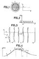
- FIG. 1 represents a test pattern to be used for implementing the invention.
- the test pattern 1 has slots such as 2, the width of which is of the order of one millimeter and which are spaced apart from one another by strips 3, of approximately twelve millimeters wide. Given an image field with a diameter of 400 millimeters, there are thirty three slits. The central slit is slightly offset from the center of the target by 3 millimeters so that if it is turned 180 degrees, we can define another pitch of slits interlaced with the first. It is assumed that this target is placed between a gamma-camera not shown (of equal image field) and a source of radiation of gamma rays of Roughly uniform emission density in the image field.
- the image of this target is analyzed according to a certain number of lines. For example, on the ordinate Yi of a line, the histogram H of the image events is noted after a certain period of time as a function of the abscissa X of the points of the line.
- the histogram H represented in FIG. 2 has the appearance of a succession of peaks approximately spaced from each other by step 3 of the test pattern 1. If we call m the maximum of these histogram peaks, we note that for the frequencies 0.35 m the width of the peaks is of the order of four millimeters. It therefore becomes useless to seek to make the image of a test pattern of finer: one would risk to see interpenetrate the crests relating to adjacent slits. For each of these crests, the abscissa Xc of the barycenter of the crest is calculated. Bearing in mind that thirty-three slots were used, thirty-three values of Xc will thus be obtained.
- the 66 abscissas of the barycentres are thus calculated for each of the ordinate lines Yi of the test image. In practice, this calculation is carried out for 512 lines using the 9 most significant bits of the ordinates of the image events taken into account.
- Figure 3 represents in the form of series of points the alignments of these barycentres as a function of their ordinate line Yi. It is obvious that they correspond to slots whose central axes a1 a2 etc ... are equidistant from each other.
- the determination of the position of the axes ai with respect to the barycenter Xc Yi is carried out by taking account of this equidistance on the one hand and by applying a method of least squares on the other hand.
- the sum of the squares of the abscissa variations DX is minimized for a set of axes ai parallel and equidistant from each other.
- the program which performs the determination of the network of lines ai also performs a line by line analysis to check whether there is no shortage of barycenter. If missing, they are determined by linear interpolation between neighboring barycenters corresponding to the same slot ai.
- the program then performs a horizontal interpolation by a set of cubic polynomials so as to arrive at 512 points from the 66 abscissas of barycenters Xc measured.
- FIG. 4 schematically represents this interpolation and shows the effect of the invention. This figure represents the displacements DX of abscissa of the barycentres at the place of the calculated abscissae Xci of these barycentres.
- a finer elementary mesh 128 ⁇ 128, is chosen, so that the curve 4 is approached precisely, and in such a way that linear interpolations on a finer mesh lead to structural errors 8 lower than the expected precision.
- the limit equations are such that the cubic polynomial passes through 9, 10 and 11, and that the derivative 12 of the polynomial in 10 is the bisector of the segments 9 - 10 and 10 - 11.
- the calculation method corrections of abscissa by a cubic polynomial gives values of DX as a function of Yi, DX (Yi), which follow each other fairly continuously according to the abscissa X.
- Yi a function of Yi
- DX (Yi) which follow each other fairly continuously according to the abscissa X.
- From one line Yi to another line immediately adjacent DX values to the same abscissa are relatively discontinuous.
- the program can then perform a vertical smoothing with variable coefficient according to the variation of the slopes in the vertical direction.
- the slits are extrapolated by parabolas.
- the very shortened slits at the edges of the field, on the right or on the left, are extrapolated by lines. This results in a marked improvement in the distortion correction at the edges of the image. This is not very useful in direct imagery (practitioners always manage to place the organ to be visualized in the middle of the image field). This is however very useful in tomography of large organs where we therefore reduce the artefacts to rings.
- DX and DY are called the two correction coefficients applied to each of the points A to D and relating respectively to segments 14 to 17, we can calculate, knowing the xy coordinates of the image event P in the elementary mesh ABCD, the image distortion corrections, DX and DY, to be applied to the XY coordinates of this point P in the image field.
Landscapes
- Physics & Mathematics (AREA)
- General Physics & Mathematics (AREA)
- Health & Medical Sciences (AREA)
- Engineering & Computer Science (AREA)
- Biomedical Technology (AREA)
- Medical Informatics (AREA)
- Nuclear Medicine, Radiotherapy & Molecular Imaging (AREA)
- Optics & Photonics (AREA)
- Life Sciences & Earth Sciences (AREA)
- General Health & Medical Sciences (AREA)
- High Energy & Nuclear Physics (AREA)
- Molecular Biology (AREA)
- Spectroscopy & Molecular Physics (AREA)
- Theoretical Computer Science (AREA)
- Image Processing (AREA)
Applications Claiming Priority (2)
| Application Number | Priority Date | Filing Date | Title |
|---|---|---|---|
| FR8707480 | 1987-05-27 | ||
| FR8707480A FR2615979B1 (fr) | 1987-05-27 | 1987-05-27 | Procede de correction de distorsion geometrique d'une image, notamment une image produite par une gamma camera |
Publications (1)
| Publication Number | Publication Date |
|---|---|
| EP0293293A1 true EP0293293A1 (de) | 1988-11-30 |
Family
ID=9351518
Family Applications (1)
| Application Number | Title | Priority Date | Filing Date |
|---|---|---|---|
| EP88401268A Withdrawn EP0293293A1 (de) | 1987-05-27 | 1988-05-25 | Verfahren zur Beseitigung von Geometrieverzerrungen eines Bildes, insbesondere für ein Bild einer Gammakamera |
Country Status (2)
| Country | Link |
|---|---|
| EP (1) | EP0293293A1 (de) |
| FR (1) | FR2615979B1 (de) |
Cited By (5)
| Publication number | Priority date | Publication date | Assignee | Title |
|---|---|---|---|---|
| WO1991001071A1 (fr) * | 1988-07-01 | 1991-01-24 | General Electric Cgr S.A. | Procede de correction de la distorsion d'images radiologiques |
| EP0450718A1 (de) * | 1990-04-02 | 1991-10-09 | Koninklijke Philips Electronics N.V. | Anordnung zum geometrischen Korrigieren eines verzerrten Bildes |
| EP0479618A3 (en) * | 1990-10-05 | 1993-11-03 | Toshiba Kk | A method and apparatus for calibrating magnetic and geometrical distortions in an imaging system |
| EP0497428B1 (de) * | 1991-01-31 | 1997-09-03 | Matsushita Electric Works, Ltd. | Türfernsprechstelle mit Fernsehsystem |
| CN119809992A (zh) * | 2025-03-14 | 2025-04-11 | 成都浩孚科技有限公司 | 一种基于结构光的探测图像畸变矫正方法及系统 |
Citations (2)
| Publication number | Priority date | Publication date | Assignee | Title |
|---|---|---|---|---|
| EP0002540A2 (de) * | 1977-12-21 | 1979-06-27 | Medtronic, Inc. | Strahlungs-Darstellungseinrichtung |
| EP0021366A1 (de) * | 1979-06-22 | 1981-01-07 | Siemens Aktiengesellschaft | Verfahren und Vorrichtung zum Korrigieren der örtlichen Verzerrung in Szintillationskameras |
-
1987
- 1987-05-27 FR FR8707480A patent/FR2615979B1/fr not_active Expired - Lifetime
-
1988
- 1988-05-25 EP EP88401268A patent/EP0293293A1/de not_active Withdrawn
Patent Citations (2)
| Publication number | Priority date | Publication date | Assignee | Title |
|---|---|---|---|---|
| EP0002540A2 (de) * | 1977-12-21 | 1979-06-27 | Medtronic, Inc. | Strahlungs-Darstellungseinrichtung |
| EP0021366A1 (de) * | 1979-06-22 | 1981-01-07 | Siemens Aktiengesellschaft | Verfahren und Vorrichtung zum Korrigieren der örtlichen Verzerrung in Szintillationskameras |
Non-Patent Citations (1)
| Title |
|---|
| IEEE TRANSACTIONS ON NUCLEAR SCIENCE, vol. NS-32, no. 1, février 1985, pages 870-874, IEEE, New York, US; S.E. KING et al.: "Spectral-spatial-sensitivity distortion trends and an accurate correction method in scintillation gamma cameras" * |
Cited By (7)
| Publication number | Priority date | Publication date | Assignee | Title |
|---|---|---|---|---|
| WO1991001071A1 (fr) * | 1988-07-01 | 1991-01-24 | General Electric Cgr S.A. | Procede de correction de la distorsion d'images radiologiques |
| US5336880A (en) * | 1988-07-01 | 1994-08-09 | General Electric Cgr S.A. | Process for the correction of distortions in radiological images |
| EP0450718A1 (de) * | 1990-04-02 | 1991-10-09 | Koninklijke Philips Electronics N.V. | Anordnung zum geometrischen Korrigieren eines verzerrten Bildes |
| NL9000766A (nl) * | 1990-04-02 | 1991-11-01 | Koninkl Philips Electronics Nv | Inrichting voor geometrische correctie van een vertekend beeld. |
| EP0479618A3 (en) * | 1990-10-05 | 1993-11-03 | Toshiba Kk | A method and apparatus for calibrating magnetic and geometrical distortions in an imaging system |
| EP0497428B1 (de) * | 1991-01-31 | 1997-09-03 | Matsushita Electric Works, Ltd. | Türfernsprechstelle mit Fernsehsystem |
| CN119809992A (zh) * | 2025-03-14 | 2025-04-11 | 成都浩孚科技有限公司 | 一种基于结构光的探测图像畸变矫正方法及系统 |
Also Published As
| Publication number | Publication date |
|---|---|
| FR2615979A1 (fr) | 1988-12-02 |
| FR2615979B1 (fr) | 1992-09-18 |
Similar Documents
| Publication | Publication Date | Title |
|---|---|---|
| EP0308315B1 (de) | Interpolationsverfahren | |
| JP4840446B2 (ja) | 放射線撮像装置 | |
| EP2761866B1 (de) | Photonenzählungskorrektur | |
| FR2741723A1 (fr) | Systeme elabore de medecine nucleaire | |
| FR2602602A1 (fr) | Dispositif et procede de correction d'image vue a vue pour le mouvement d'un objet | |
| JPS63308548A (ja) | マイクロトモグラフィシステムに電気・光学式検出器を使用する装置 | |
| JP2022145494A (ja) | 画像処理装置、補正方法及びプログラム | |
| FR2750821A1 (fr) | Procede et dispositif pour la prise d'images numeriques avec controle et optimisation du temps d'exposition de l'objet a des rayonnements x ou y | |
| US7649175B2 (en) | Analog to digital conversion shift error correction | |
| WO2019215178A1 (en) | Photon counting spectral ct | |
| FR2941348A1 (fr) | Technique d'etalonnage et de correction de gain pour systemes d'imagerie numerique. | |
| US7075061B2 (en) | Method of calibrating a digital X-ray detector and corresponding X-ray device | |
| US5576547A (en) | Position calculation and energy correction in the digital scintillation camera | |
| EP0293293A1 (de) | Verfahren zur Beseitigung von Geometrieverzerrungen eines Bildes, insbesondere für ein Bild einer Gammakamera | |
| EP0297934B1 (de) | Verfahren zur Bestimmung der Lokalisierungsimpulse einer Gammakamera | |
| EP1037070A1 (de) | Verfahren und Vorrichtung zur Klassifizierung von festgestellten Ereignissen eines Gammastrahlungsdetektors im Echtzeitbetrieb | |
| EP0295986B1 (de) | Vorrichtung zur Kern-Strahlungslokalisierung und Strahlungsbilderzeugung | |
| JP2007510150A (ja) | ピクセル状固体検出器のための較正方法および装置 | |
| CN109549662A (zh) | 一种调整电容档位的方法、装置及存储介质 | |
| JP5522350B2 (ja) | Ct装置 | |
| FR3131392A1 (fr) | Procédé de formation et de traitement d’une image gamma | |
| FR2755816A1 (fr) | Procede et dispositif de traitement des signaux d'un ensemble de photodetecteurs ayant une architecture cellulaire, et application aux gamma-cameras | |
| FR2479990A1 (fr) | Dispositif electronique de correction des defauts de linearite d'une camera de gammagraphie de type anger | |
| FR2506029A1 (fr) | Procede de correction de distorsions dans une camera a scintillation, et camera a scintillation a distorsions corrigees | |
| CN114359234A (zh) | 一种多床位图像采集和实时计数校正方法 |
Legal Events
| Date | Code | Title | Description |
|---|---|---|---|
| PUAI | Public reference made under article 153(3) epc to a published international application that has entered the european phase |
Free format text: ORIGINAL CODE: 0009012 |
|
| AK | Designated contracting states |
Kind code of ref document: A1 Designated state(s): DE GB NL |
|
| 17P | Request for examination filed |
Effective date: 19890506 |
|
| 17Q | First examination report despatched |
Effective date: 19900704 |
|
| STAA | Information on the status of an ep patent application or granted ep patent |
Free format text: STATUS: THE APPLICATION IS DEEMED TO BE WITHDRAWN |
|
| 18D | Application deemed to be withdrawn |
Effective date: 19910430 |