EP0308016A2 - Sliding valve for liquid or gas conduits - Google Patents
Sliding valve for liquid or gas conduits Download PDFInfo
- Publication number
- EP0308016A2 EP0308016A2 EP88201962A EP88201962A EP0308016A2 EP 0308016 A2 EP0308016 A2 EP 0308016A2 EP 88201962 A EP88201962 A EP 88201962A EP 88201962 A EP88201962 A EP 88201962A EP 0308016 A2 EP0308016 A2 EP 0308016A2
- Authority
- EP
- European Patent Office
- Prior art keywords
- opening
- valve
- liquid
- gas
- valve according
- Prior art date
- Legal status (The legal status is an assumption and is not a legal conclusion. Google has not performed a legal analysis and makes no representation as to the accuracy of the status listed.)
- Granted
Links
Images
Classifications
-
- F—MECHANICAL ENGINEERING; LIGHTING; HEATING; WEAPONS; BLASTING
- F16—ENGINEERING ELEMENTS AND UNITS; GENERAL MEASURES FOR PRODUCING AND MAINTAINING EFFECTIVE FUNCTIONING OF MACHINES OR INSTALLATIONS; THERMAL INSULATION IN GENERAL
- F16K—VALVES; TAPS; COCKS; ACTUATING-FLOATS; DEVICES FOR VENTING OR AERATING
- F16K3/00—Gate valves or sliding valves, i.e. cut-off apparatus with closing members having a sliding movement along the seat for opening and closing
- F16K3/02—Gate valves or sliding valves, i.e. cut-off apparatus with closing members having a sliding movement along the seat for opening and closing with flat sealing faces; Packings therefor
- F16K3/0209—Gate valves or sliding valves, i.e. cut-off apparatus with closing members having a sliding movement along the seat for opening and closing with flat sealing faces; Packings therefor the valve having a particular passage, e.g. provided with a filter, throttle or safety device
-
- F—MECHANICAL ENGINEERING; LIGHTING; HEATING; WEAPONS; BLASTING
- F16—ENGINEERING ELEMENTS AND UNITS; GENERAL MEASURES FOR PRODUCING AND MAINTAINING EFFECTIVE FUNCTIONING OF MACHINES OR INSTALLATIONS; THERMAL INSULATION IN GENERAL
- F16K—VALVES; TAPS; COCKS; ACTUATING-FLOATS; DEVICES FOR VENTING OR AERATING
- F16K3/00—Gate valves or sliding valves, i.e. cut-off apparatus with closing members having a sliding movement along the seat for opening and closing
- F16K3/02—Gate valves or sliding valves, i.e. cut-off apparatus with closing members having a sliding movement along the seat for opening and closing with flat sealing faces; Packings therefor
- F16K3/0227—Packings
Definitions
- the invention relates to a slide valve with or without a pressure regulator for liquid or gas pipes.
- a sliding valve intended to stop liquids, gases or vapors circulating in pipes or to regulate the quantity which passes.
- a slide which is slidable from bottom to top and from top to bottom against one or two valve seats.
- a valve is designed in which the pressure difference is compensated and no pressure difference acts on the stop elements, whereby the friction force to be overcome, which depends on the pressure exerted, is significantly reduced.
- This valve mainly comprises a closed body, a supply channel which opens into said body and is connected to the liquid or gas supply pipe, a passage chamber with two walls placed one opposite the other.
- an evacuation channel which opens on one side into the passage chamber and is connected on the other side to the liquid or gas evacuation pipe, in at least one of the aforementioned walls from the passage chamber an opening which puts the body in communication with the passage chamber, a valve body disposed between said walls and opening for closing this opening, a height-adjustable or pivoting rod to which said valve body is attached, means for adjusting said rod, at least one closure element made of hard material between said valve body and said wall with opening on one side and the other wall on the other side, and at least one elastic element to press one against the other the Said closure elements and the valve body in a water and gas tight manner.
- valve body By the fact that in the closed position of the valve body the pressure of the incoming liquid or gas acts on both sides of the valve body, a balance is created, as a result of which the valve body is movable independently of the pressure. This effect becomes even more noticeable when the valve body is perforated, so that in the closed position thereof the liquid or gas can freely pass through. In addition, in the event of a sudden production of a pressure difference, the valve body will not be subjected to an impact, so that the fracture of this body will be avoided.
- the body 1 of the valve with the passage chamber 2, which is provided at the bottom of two parallel walls, in which are arranged two openings 3 located one opposite the other.
- the passage chamber 2 has an evacuation channel 4.
- the body 1 has at the top a supply channel 5, so that a liquid or a gas entering through this supply channel into the body is diverted via the openings 3, the passage chamber 2 and the evacuation channel 4 and is evacuated.
- a screw connection 6 is attached by means of a coupling nut 7 to which the screw connections are connected respectively a supply line and a supply line. evacuation (not shown) of a water or gas pipe.
- the open upper part of the body 1 is closed by means of a hollow head 8 fixed to the body 1 by means of screws 9.
- two manometers, respectively 10 and 11, which via a perforation, respectively 12- 13, are in communication with the supply channel 5 and the discharge channel 4 respectively, so that the pressure of the liquid or gas entering and leaving can be controlled.
- the lower part of the body 1 is closed by means of a bell 14, which is fixed to the body 1 by means of a coupling nut 15.
- the body has a narrowed part, the two parallel flat walls of which with the openings 3 provided therein are part.
- a frame 16 with two openings 17 with profiled edge, which openings of the frame adapt to said openings 3, so that the frame is sufficiently tightened.
- a filter 19 is tightened by means of a sealing ring 18, so that the liquid or the gas is forced to pass through this filter before being evacuated by the evacuation channel 4.
- a circular closing element 20 preferably made of hard ceramic, which by means of a circular elastic element 21 bears against the inside of the profiled edge of the adjacent opening 17 of the frame 16 that the element in question is axially displaceable and that a good seal is obtained.
- each annular stop element 20 operates an annular element stop 22, preferably hard ceramic, and which is part of the valve body 35 itself.
- annular stop elements are housed in an opening 23 in the head of a rod 24 movable in height.
- Each annular stop element is pushed against its respective annular stop element 20 by an elastic annular element 25, which is placed between this annular stop element and an intermediate ring 26 placed in said head of the rod 24 movable in height .
- the elastic annular elements 21 and 25 the annular stop elements 20 are strongly pushed one against the other, regardless of the position of the stop elements 22 relative to the stop elements 20. A closure perfect is therefore possible thanks to this.
- the rod 24 movable in height is fixed in a clamping member 27, which in turn is fixed on a hollow cylinder head 28. Between this hollow cylinder head and the head 8 are placed two pressure springs, respectively 29-30, whose pressure power is chosen so that the valve can only close when the incoming liquid or gas reaches a determined pressure. This part of the valve therefore serves as a pressure regulator.
- a membrane 31 which completely separates the space in the hollow head 8 from that of the body 1.
- the space in said head is in communication with the atmosphere by a bore 32 provided in the head.
- a guide pin 33 forming part of the head freely slides a guide box 34 forming part of the cylinder head 28, so that the cylinder head is effectively guided during its movement.
Abstract
Description
L'invention concerne une vanne à coulisse pourvue ou non d'un régulateur de pression pour conduites de liquide ou de gaz.The invention relates to a slide valve with or without a pressure regulator for liquid or gas pipes.
On connaît une vanne à coulisse destinée à arrêter des liquides, des gaz ou des vapeurs circulant dans des conduites ou à en régler la quantité qui passe. Dans son cas, dans le corps de la vanne pourvue d'un canal d'amenée et d'un canal d'évacuation est placée une coulisse qui est coulissable de bas en haut et de haut en bas contre un ou deux sièges de clapet.There is a sliding valve intended to stop liquids, gases or vapors circulating in pipes or to regulate the quantity which passes. In its case, in the body of the valve provided with a supply channel and a discharge channel is placed a slide which is slidable from bottom to top and from top to bottom against one or two valve seats.
Cette vanne à coulisse a toutefois pour inconvénient que, quand elle est fermée, la coulisse est pressée contre le siège de clapet par la pression du liquide ou du gaz qui entre, de sorte que pour l'ouverture de la coulisse une puissante force de frottement doit être surmontée qui est proportionnelle à la différence de pression qui agit sur la coulisse, par suite de quoi la force de mouvement nécessaire au déplacement de la coulisse dépend dans une large mesure de la pression présente. Un autre inconvénient est que, quand soudain une trop grande différence de pression est créée dans le liquide ou le gaz, une force de choc est exercée contre la coulisse, par suite de quoi une fracture peut s'y produire. Encore un autre inconvénient est le fait qu'à cette vanne connue la coulisse est pressée contre le clapet de siège uniquement par la différence de pression, par suite de quoi en cas d'absence d'un moyen de pression comme un ressort, lors d'une faible différence de pression, une fuite peut se produire.The drawback of this slide valve, however, is that when it is closed, the slide is pressed against the valve seat by the pressure of the liquid or gas which enters, so that for the opening of the slide a powerful friction force must be overcome which is proportional to the pressure difference acting on the slide, as a result of which the force of movement necessary for the movement of the slide depends to a large extent on the pressure present. Another disadvantage is that when suddenly too big a difference pressure is created in the liquid or gas, an impact force is exerted against the slide, as a result of which a fracture can occur there. Yet another drawback is the fact that at this known valve the slide is pressed against the seat valve only by the pressure difference, as a result of which in the absence of a pressure means such as a spring, during '' a small pressure difference, a leak may occur.
Pour y remédier, selon la caractéristique principale de l'invention, une vanne est conçue dans laquelle la différence de pression est compensée et aucune différence de pression n'agit sur les éléments d'arrêt, grâce à quoi la force de frottement à surmonter, qui dépend de la pression exercée, est sensiblement diminuée. Cette vanne comprend principalement un corps fermé, un canal d'amenée qui débouche dans ledit corps et est raccordé à la conduite d'amenée de liquide ou de gaz, une chambre de passage avec deux parois placées l'une en face de l'autre et logées dans ledit corps, un canal d'évacuation, qui débouche d'un côté dans la chambre de passage et est raccordé de l'autre côté à la conduite d'évacuation du liquide ou du gaz, dans au moins une des parois précitées de la chambre de passage une ouverture qui met le corps en communication avec la chambre de passage, un corps de clapet disposé entre lesdites parois et ouverture pour la fermeture de cette ouverture, une tige réglable en hauteur ou pivotante à laquelle ledit corps de clapet est attaché, un moyen de réglage de ladite tige, au moins un élément de fermeture en matière dure entre ledit corps de clapet et ladite paroi avec ouverture d'un côté et l'autre paroi de l'autre côté, et au moins un élément élastique pour presser l'un contre l'autre lesdits éléments de fermeture et le corps de clapet d'une manière étanche à l'eau et au gaz.To remedy this, according to the main characteristic of the invention, a valve is designed in which the pressure difference is compensated and no pressure difference acts on the stop elements, whereby the friction force to be overcome, which depends on the pressure exerted, is significantly reduced. This valve mainly comprises a closed body, a supply channel which opens into said body and is connected to the liquid or gas supply pipe, a passage chamber with two walls placed one opposite the other. and housed in said body, an evacuation channel, which opens on one side into the passage chamber and is connected on the other side to the liquid or gas evacuation pipe, in at least one of the aforementioned walls from the passage chamber an opening which puts the body in communication with the passage chamber, a valve body disposed between said walls and opening for closing this opening, a height-adjustable or pivoting rod to which said valve body is attached, means for adjusting said rod, at least one closure element made of hard material between said valve body and said wall with opening on one side and the other wall on the other side, and at least one elastic element to press one against the other the Said closure elements and the valve body in a water and gas tight manner.
Par le fait que dans la position fermée du corps de clapet la pression du liquide ou du gaz entrant agit sur les deux côtés du corps de clapet, il se crée un équilibre, par suite duquel le corps de clapet est déplaçable indépendamment de la pression. Cet effet devient encore plus nettement perceptible quand le corps de clapet est perforé, de sorte que dans la position fermée de celui-ci le liquide ou le gaz peut librement passer à travers. En outre, en cas de production soudaine d'une différence de pression, le corps de clapet ne sera pas soumis à un choc, de sorte que la fracture de ce corps sera évitée.By the fact that in the closed position of the valve body the pressure of the incoming liquid or gas acts on both sides of the valve body, a balance is created, as a result of which the valve body is movable independently of the pressure. This effect becomes even more noticeable when the valve body is perforated, so that in the closed position thereof the liquid or gas can freely pass through. In addition, in the event of a sudden production of a pressure difference, the valve body will not be subjected to an impact, so that the fracture of this body will be avoided.
A titre d'exemple, sans aucun caractère limitatif, une description plus détaillée d'une forme choisie de réalisation d'une vanne avec régulateur de pression conforme à l'invention suit ci-dessous.By way of example, without any limiting character, a more detailed description of a chosen embodiment of a valve with pressure regulator according to the invention follows below.
Cette description renvoie aux dessins annexés, dans lesquels :
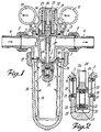
- la fig. 1 représente une coupe verticale de la vanne à régulateur de pression en position ouverte;
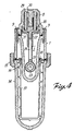
- la fig. 2 représente une coupe verticale agrandie de la partie clapet proprement dite de la vanne;
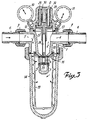
- la fig. 3 représente une coupe verticale de la vanne à régulateur de pression en position fermée;
- la fig. 4 représente une coupe transversale verticale de la vanne à régulateur de pression, dans un plan perpendiculaire au plan de la coupe transversale représentée dans la fig. 1.
- fig. 1 shows a vertical section of the pressure regulator valve in the open position;
- fig. 2 shows an enlarged vertical section of the valve part proper of the valve;
- fig. 3 shows a vertical section of the pressure regulator valve in the closed position;
- fig. 4 shows a vertical cross section of the pressure regulator valve, in a plane perpendicular to the plane of the cross section shown in FIG. 1.
Dans ces figures on remarque le corps 1 de la vanne avec la chambre de passage 2, qui est pourvue en bas de deux parois parallèles, dans lesquelles sont aménagées deux ouvertures 3 situées l'une en face de l'autre. En haut, la chambre de passage 2 a un canal d'évacuation 4. Le corps 1 possède en haut un canal d'amenée 5, de sorte qu'un liquide ou un gaz entrant par ce canal d'amenée dans le corps est détourné via les ouvertures 3, la chambre de passage 2 et le canal d'évacuation 4 et est évacué. Sur le canal d'amenée 5 et le canal d'évacuation 4 respectivement, un raccord à vis 6 est attaché au moyen d'un écrou d'accouplement 7 auxquels raccords à vis sont raccordés respectivement une conduite d'amenée et une conduite d'évacuation (non représentées) d'une conduite d'eau ou de gaz. La partie supérieure ouverte du corps 1 est fermée au moyen d'une tête creuse 8 fixée sur le corps 1 au moyen de vis 9. Sur ladite tete 8 sont montés deux manomètres, respectivement 10 et 11, qui via une perforation, respectivement 12-13, sont en communication avec le canal d'amenée 5 et le canal d'évacuation 4 respectivement, de sorte que la pression du liquide ou du gaz qui entre et qui sort peut être contrôlée. La partie inférieure du corps 1 est fermée au moyen d'une cloche 14, qui est fixée sur le corps 1 au moyen d'un écrou d'accouplement 15. En bas, le corps a une partie rétrécie, dont les deux parois plates parallèles avec les ouvertures 3 y prévues font partie. Autour de cette partie rétrécie est fixée une armature 16 à deux ouvertures 17 à bord profilé, lesquelles ouvertures de l'armature s'adaptent auxdites ouvertures 3, de sorte que l'armature est suffisamment serrée. Autour de cette armature un filtre 19 est serré par l'intermédiaire d'un anneau d'étanchéité 18, de sorte que le liquide ou le gaz est obligé de passer par ce filtre avant d'être évacué par le canal d'évacuation 4. Dans chaque ouverture 3 du corps 1 est également aménagé avec du jeu un élément de fermeture circulaire 20 en céramique dure de préférence, qui par l'intermédiaire d'un élément élastique circulaire 21 s'appuie contre le côté intérieur du bord profilé de l'ouverture adjacente 17 de l'armature 16 que l'élément en question est axialement déplaçable et qu'une bonne étanchéité est obtenue. Avec chaque élément annulaire d'arrêt 20 opère un élément annulaire d'arrêt 22, de préférence en céramique dure, et qui fait partie du corps de clapet 35 proprement dit. Ces éléments annulaires d'arrêt sont logés dans une ouverture 23 de la tête d'une tige 24 déplaçable en hauteur. Chaque élément annulaire d'arret est poussé contre son élément annulaire d'arrêt 20 respectif par un élément annulaire élastique 25, qui est placé entre cet élément annulaire d'arrêt et un anneau intermédiaire 26 placé dans ladite tête de la tige 24 déplaçable en hauteur. Par les éléments annulaires élastiques 21 et 25 les éléments annulaires d'arrêt 20 sont fortement poussés l'un contre l'autre, et ce quelle que soit la position des éléments d'arret 22 par rapport aux éléments d'arrêt 20. Une fermeture parfaite est donc possible grâce à cela. Du fait qu'aucune différence de pression ne peut être exercée par le liquide ou le gaz entrant sur le corps de clapet 35 proprement dit, sans que celui-ci soit soutenu, une rupture des éléments d'arrêt en cas de différence de pression intervenant brusquement n'est pas à craindre et la force de mouvement pour le déplacement en hauteur du corps de clapet 35 ne dépend pas de la différence de pression. En haut, la tige 24 déplaçable en hauteur est fixée dans un organe de serrage 27, qui à son tour est fixé sur une culasse creuse 28. Entre cette culasse creuse et la tête 8 sont placés deux ressorts de pression, respectivement 29-30, dont la puissance de pression est choisie de manière telle que le clapet ne peut fermer que quand le liquide ou le gaz entrant atteint une pression déterminée. Cette partie de la vanne sert donc de régulateur de pression. Entre la tête 8 et la culasse 28 est placée une membrane 31, qui sépare complètement l'espace dans la tête creuse 8 de celui du corps 1. L'espace dans ladite tête est en communication avec l'atmosphère par une forure 32 prévue dans la tête. Par une cheville de guidage 33 faisant partie de la tête glisse librement une boîte de guidage 34 faisant partie de la culasse 28, de sorte que la culasse est efficacement guidée pendant son déplacement.In these figures we see the
Quand la pression du liquide ou du gaz entrant est plus faible que la pression exercée par les ressorts de pression 29-30, ceux-ci poussent la culasse 28, la tige 24 et le corps de clapet 35 vers le bas (fig. 1), de sorte que le liquide ou le gaz passe librement par le canal d'amenée 5, par le filtre 19, par les ouvertures 3-17, par la chambre de passage 2 du corps 1 et par le canal d'évacuation 4.When the pressure of the incoming liquid or gas is lower than the pressure exerted by the pressure springs 29-30, these push the
Mais quand la pression du liquide ou du gaz entrant dans la vanne devient plus forte que la pression exercée par le ressort de pression 29-30 logé dans la tête 8, le liquide ou le gaz exercera une telle pression sur la surface inférieure de l'organe de serrage 27 que la tige 24 avec le corps de clapet 35 y attaché sont déplacés vers le haut, jusqu'à ce que les éléments annulaires d'arrêt 22 recouvrent les éléments annulaires d'arrêt 20 et que le liquide ou le gaz ne peut plus passer par la chambre de passage 2 du corps 1 vers le canal d'évacuation 4, mais continue à passer ordinairement par les éléments annulaires d'arrêt 20, les éléments d'arrêt 22 et l'anneau intermédiaire 26 (fig. 3). Les éléments annulaires d'arrêt 22 en céramique dure et les éléments d'arrêt 20, qui sont pressés l'un contre l'autre par les élements annulaires élastiques 21 et 25, tandis que leur déplacement l'un par rapport à l'autre sans frottement exagéré reste possible, assurent une fermeture parfaite.But when the pressure of the liquid or gas entering the valve becomes higher than the pressure exerted by the pressure spring 29-30 housed in the
Quand alors la pression du liquide ou du gaz diminue de nouveau, les ressorts de pression 29-30 pousseront de nouveau le corps de clapet 35 vers le bas et le liquide ou le gaz passe de nouveau librement par la vanne et le canal d'évacuation.When the pressure of the liquid or gas then decreases again, the pressure springs 29-30 will again push the
Il va de soi que la forme, les dimensions, le nombre et la disposition réciproque des éléments décrits ci-dessus peuvent différer à condition de rester dans le cadre de l'invention. Il va également de soi que certaines des pièces de rechange décrites ci-dessus pourraient être remplacées par d'autres qui poursuivent le même but.It goes without saying that the shape, dimensions, number and reciprocal arrangement of the elements described above may differ provided that they remain within the scope of the invention. It also goes without saying that some of the spare parts described above could be replaced by others which serve the same purpose.
Claims (9)
Priority Applications (1)
| Application Number | Priority Date | Filing Date | Title |
|---|---|---|---|
| AT88201962T ATE98756T1 (en) | 1987-09-17 | 1988-09-08 | SLIDE VALVE FOR LIQUID OR GAS LINES. |
Applications Claiming Priority (2)
| Application Number | Priority Date | Filing Date | Title |
|---|---|---|---|
| BE8701050 | 1987-09-17 | ||
| BE8701050A BE1000929A7 (en) | 1987-09-17 | 1987-09-17 | Gate valve for liquid or gas. |
Publications (3)
| Publication Number | Publication Date |
|---|---|
| EP0308016A2 true EP0308016A2 (en) | 1989-03-22 |
| EP0308016A3 EP0308016A3 (en) | 1989-08-23 |
| EP0308016B1 EP0308016B1 (en) | 1993-12-15 |
Family
ID=3882864
Family Applications (1)
| Application Number | Title | Priority Date | Filing Date |
|---|---|---|---|
| EP88201962A Expired - Lifetime EP0308016B1 (en) | 1987-09-17 | 1988-09-08 | Sliding valve for liquid or gas conduits |
Country Status (5)
| Country | Link |
|---|---|
| EP (1) | EP0308016B1 (en) |
| AT (1) | ATE98756T1 (en) |
| BE (1) | BE1000929A7 (en) |
| DE (1) | DE3886321T2 (en) |
| ES (1) | ES2048196T3 (en) |
Citations (3)
| Publication number | Priority date | Publication date | Assignee | Title |
|---|---|---|---|---|
| US4372531A (en) * | 1980-11-18 | 1983-02-08 | Maxon Corporation | Ceramic gate valve and components therefor |
| WO1985004700A1 (en) * | 1984-04-10 | 1985-10-24 | Jankovic Mladen | Wedge-type valve |
| EP0176867A2 (en) * | 1984-09-25 | 1986-04-09 | Hans Sasserath & Co Kg | Filter fitting with integrated pressure reduction valve |
-
1987
- 1987-09-17 BE BE8701050A patent/BE1000929A7/en not_active IP Right Cessation
-
1988
- 1988-09-08 DE DE88201962T patent/DE3886321T2/en not_active Expired - Fee Related
- 1988-09-08 EP EP88201962A patent/EP0308016B1/en not_active Expired - Lifetime
- 1988-09-08 ES ES88201962T patent/ES2048196T3/en not_active Expired - Lifetime
- 1988-09-08 AT AT88201962T patent/ATE98756T1/en not_active IP Right Cessation
Patent Citations (3)
| Publication number | Priority date | Publication date | Assignee | Title |
|---|---|---|---|---|
| US4372531A (en) * | 1980-11-18 | 1983-02-08 | Maxon Corporation | Ceramic gate valve and components therefor |
| WO1985004700A1 (en) * | 1984-04-10 | 1985-10-24 | Jankovic Mladen | Wedge-type valve |
| EP0176867A2 (en) * | 1984-09-25 | 1986-04-09 | Hans Sasserath & Co Kg | Filter fitting with integrated pressure reduction valve |
Also Published As
| Publication number | Publication date |
|---|---|
| ATE98756T1 (en) | 1994-01-15 |
| DE3886321D1 (en) | 1994-01-27 |
| DE3886321T2 (en) | 1994-03-31 |
| EP0308016A3 (en) | 1989-08-23 |
| EP0308016B1 (en) | 1993-12-15 |
| BE1000929A7 (en) | 1989-05-16 |
| ES2048196T3 (en) | 1994-03-16 |
Similar Documents
| Publication | Publication Date | Title |
|---|---|---|
| FR2762933A1 (en) | VALVE PLUG FOR ELECTRIC ACCUMULATOR | |
| FR2772354A1 (en) | FILL LIMITER FOR LIQUID STORAGE TANK | |
| EP0952376A1 (en) | Double-seat lift valve with inflatable membrane | |
| FR2831875A1 (en) | TANK CAP | |
| FR2652426A1 (en) | GAS BOTTLE REGULATOR. | |
| EP0308016B1 (en) | Sliding valve for liquid or gas conduits | |
| FR2894642A1 (en) | SANDWICH CLUTCH WITH DIRECT ACTION | |
| FR2776045A1 (en) | THREE-WAY VALVE FOR PRESSURE REGULATION OF FLUID, ESPECIALLY OF HIGH PRESSURE FLUID | |
| FR2727773A1 (en) | Underground gas pressure regulator protected against flooding | |
| FR2528517A1 (en) | SHUTTER FOR MOUNTING INTO A BODY | |
| EP1380779B1 (en) | Pressure relief valve | |
| CH713978A2 (en) | Security valve for watch. | |
| FR2509827A1 (en) | PRESSURE CONTROL VALVE | |
| FR2544832A1 (en) | Non-return device for a water supply network | |
| FR2558562A1 (en) | Pilot-controlled pneumatic valve. | |
| FR2624946A1 (en) | DIRECT ACTION SAFETY VALVE | |
| FR2542346A1 (en) | TAP FOR WATER HUNTING TANK | |
| FR2593262A1 (en) | VALVE HEAD ADAPTABLE TO A VALVE ROD | |
| FR2472684A1 (en) | DEVICE FOR CONTROLLING A SWITCHING MEMBER, ACTUATED BY A PRESSURE PULSE AND WITH BRAKE RECALL | |
| FR2524173A1 (en) | Liq. level control for automatic tank filling system - has level sensing float whose movement initiates progressive closure of main supply valve | |
| FR2778397A1 (en) | FILLING DEVICE FOR LIQUEFIED PETROLEUM GAS TANK | |
| FR2481404A1 (en) | Water feed valve with push flow control - has rotary sleeve regulation cutting by pass flow for membrane to move washer onto seat | |
| FR2618874A1 (en) | AUTOMATIC MEMBRANE PURGE DEVICE FOR PNEUMATIC CIRCUITS | |
| BE1003878A3 (en) | Discharge valve | |
| CH610211A5 (en) | Cock for pipe conveying fluid at pressure |
Legal Events
| Date | Code | Title | Description |
|---|---|---|---|
| PUAI | Public reference made under article 153(3) epc to a published international application that has entered the european phase |
Free format text: ORIGINAL CODE: 0009012 |
|
| AK | Designated contracting states |
Kind code of ref document: A2 Designated state(s): AT BE CH DE ES FR GB LI NL |
|
| PUAL | Search report despatched |
Free format text: ORIGINAL CODE: 0009013 |
|
| RHK1 | Main classification (correction) |
Ipc: B01D 35/14 |
|
| AK | Designated contracting states |
Kind code of ref document: A3 Designated state(s): AT BE CH DE ES FR GB LI NL |
|
| 17P | Request for examination filed |
Effective date: 19900131 |
|
| RAP1 | Party data changed (applicant data changed or rights of an application transferred) |
Owner name: S.MC.D. MURPHY & PARTNERS LTD. |
|
| 17Q | First examination report despatched |
Effective date: 19920124 |
|
| GRAA | (expected) grant |
Free format text: ORIGINAL CODE: 0009210 |
|
| AK | Designated contracting states |
Kind code of ref document: B1 Designated state(s): AT BE CH DE ES FR GB LI NL |
|
| REF | Corresponds to: |
Ref document number: 98756 Country of ref document: AT Date of ref document: 19940115 Kind code of ref document: T |
|
| GBT | Gb: translation of ep patent filed (gb section 77(6)(a)/1977) |
Effective date: 19931215 |
|
| REF | Corresponds to: |
Ref document number: 3886321 Country of ref document: DE Date of ref document: 19940127 |
|
| REG | Reference to a national code |
Ref country code: ES Ref legal event code: FG2A Ref document number: 2048196 Country of ref document: ES Kind code of ref document: T3 |
|
| PG25 | Lapsed in a contracting state [announced via postgrant information from national office to epo] |
Ref country code: AT Effective date: 19940908 |
|
| PG25 | Lapsed in a contracting state [announced via postgrant information from national office to epo] |
Ref country code: LI Effective date: 19940930 Ref country code: CH Effective date: 19940930 |
|
| PLBE | No opposition filed within time limit |
Free format text: ORIGINAL CODE: 0009261 |
|
| STAA | Information on the status of an ep patent application or granted ep patent |
Free format text: STATUS: NO OPPOSITION FILED WITHIN TIME LIMIT |
|
| 26N | No opposition filed | ||
| PGFP | Annual fee paid to national office [announced via postgrant information from national office to epo] |
Ref country code: FR Payment date: 19941223 Year of fee payment: 7 Ref country code: BE Payment date: 19941223 Year of fee payment: 7 |
|
| PGFP | Annual fee paid to national office [announced via postgrant information from national office to epo] |
Ref country code: ES Payment date: 19941230 Year of fee payment: 7 |
|
| PGFP | Annual fee paid to national office [announced via postgrant information from national office to epo] |
Ref country code: DE Payment date: 19950103 Year of fee payment: 7 |
|
| PGFP | Annual fee paid to national office [announced via postgrant information from national office to epo] |
Ref country code: GB Payment date: 19950106 Year of fee payment: 7 |
|
| PG25 | Lapsed in a contracting state [announced via postgrant information from national office to epo] |
Ref country code: NL Effective date: 19950401 |
|
| NLV4 | Nl: lapsed or anulled due to non-payment of the annual fee | ||
| REG | Reference to a national code |
Ref country code: CH Ref legal event code: PL |
|
| REG | Reference to a national code |
Ref country code: CH Ref legal event code: AUV Free format text: LE BREVET CI-DESSUS EST TOMBE EN DECHEANCE FAUTE DE PAIEMENT, DE LA 7E ANNUITE. |
|
| PG25 | Lapsed in a contracting state [announced via postgrant information from national office to epo] |
Ref country code: GB Effective date: 19950908 |
|
| PG25 | Lapsed in a contracting state [announced via postgrant information from national office to epo] |
Ref country code: ES Free format text: LAPSE BECAUSE OF THE APPLICANT RENOUNCES Effective date: 19950909 |
|
| PG25 | Lapsed in a contracting state [announced via postgrant information from national office to epo] |
Ref country code: BE Effective date: 19950930 |
|
| BERE | Be: lapsed |
Owner name: S.MC.D. MURPHY & PARTNERS LTD Effective date: 19950930 |
|
| GBPC | Gb: european patent ceased through non-payment of renewal fee |
Effective date: 19950908 |
|
| PG25 | Lapsed in a contracting state [announced via postgrant information from national office to epo] |
Ref country code: FR Effective date: 19960531 |
|
| PG25 | Lapsed in a contracting state [announced via postgrant information from national office to epo] |
Ref country code: DE Effective date: 19960601 |
|
| REG | Reference to a national code |
Ref country code: FR Ref legal event code: ST |
|
| REG | Reference to a national code |
Ref country code: ES Ref legal event code: FD2A Effective date: 19991007 |