EP0952376A1 - Double-seat lift valve with inflatable membrane - Google Patents
Double-seat lift valve with inflatable membrane Download PDFInfo
- Publication number
- EP0952376A1 EP0952376A1 EP19990400826 EP99400826A EP0952376A1 EP 0952376 A1 EP0952376 A1 EP 0952376A1 EP 19990400826 EP19990400826 EP 19990400826 EP 99400826 A EP99400826 A EP 99400826A EP 0952376 A1 EP0952376 A1 EP 0952376A1
- Authority
- EP
- European Patent Office
- Prior art keywords
- valve
- membrane
- chamber
- valves
- pressurized air
- Prior art date
- Legal status (The legal status is an assumption and is not a legal conclusion. Google has not performed a legal analysis and makes no representation as to the accuracy of the status listed.)
- Granted
Links
Images

Classifications
-
- F—MECHANICAL ENGINEERING; LIGHTING; HEATING; WEAPONS; BLASTING
- F16—ENGINEERING ELEMENTS AND UNITS; GENERAL MEASURES FOR PRODUCING AND MAINTAINING EFFECTIVE FUNCTIONING OF MACHINES OR INSTALLATIONS; THERMAL INSULATION IN GENERAL
- F16K—VALVES; TAPS; COCKS; ACTUATING-FLOATS; DEVICES FOR VENTING OR AERATING
- F16K1/00—Lift valves or globe valves, i.e. cut-off apparatus with closure members having at least a component of their opening and closing motion perpendicular to the closing faces
- F16K1/32—Details
- F16K1/34—Cutting-off parts, e.g. valve members, seats
- F16K1/44—Details of seats or valve members of double-seat valves
- F16K1/443—Details of seats or valve members of double-seat valves the seats being in series
- F16K1/446—Details of seats or valve members of double-seat valves the seats being in series with additional cleaning or venting means between the two seats
-
- Y—GENERAL TAGGING OF NEW TECHNOLOGICAL DEVELOPMENTS; GENERAL TAGGING OF CROSS-SECTIONAL TECHNOLOGIES SPANNING OVER SEVERAL SECTIONS OF THE IPC; TECHNICAL SUBJECTS COVERED BY FORMER USPC CROSS-REFERENCE ART COLLECTIONS [XRACs] AND DIGESTS
- Y10—TECHNICAL SUBJECTS COVERED BY FORMER USPC
- Y10T—TECHNICAL SUBJECTS COVERED BY FORMER US CLASSIFICATION
- Y10T137/00—Fluid handling
- Y10T137/4238—With cleaner, lubrication added to fluid or liquid sealing at valve interface
- Y10T137/4245—Cleaning or steam sterilizing
- Y10T137/4259—With separate material addition
-
- Y—GENERAL TAGGING OF NEW TECHNOLOGICAL DEVELOPMENTS; GENERAL TAGGING OF CROSS-SECTIONAL TECHNOLOGIES SPANNING OVER SEVERAL SECTIONS OF THE IPC; TECHNICAL SUBJECTS COVERED BY FORMER USPC CROSS-REFERENCE ART COLLECTIONS [XRACs] AND DIGESTS
- Y10—TECHNICAL SUBJECTS COVERED BY FORMER USPC
- Y10T—TECHNICAL SUBJECTS COVERED BY FORMER US CLASSIFICATION
- Y10T137/00—Fluid handling
- Y10T137/5762—With leakage or drip collecting
-
- Y—GENERAL TAGGING OF NEW TECHNOLOGICAL DEVELOPMENTS; GENERAL TAGGING OF CROSS-SECTIONAL TECHNOLOGIES SPANNING OVER SEVERAL SECTIONS OF THE IPC; TECHNICAL SUBJECTS COVERED BY FORMER USPC CROSS-REFERENCE ART COLLECTIONS [XRACs] AND DIGESTS
- Y10—TECHNICAL SUBJECTS COVERED BY FORMER USPC
- Y10T—TECHNICAL SUBJECTS COVERED BY FORMER US CLASSIFICATION
- Y10T137/00—Fluid handling
- Y10T137/8593—Systems
- Y10T137/87917—Flow path with serial valves and/or closures
- Y10T137/88038—One valve head carries other valve head
Definitions
- the invention relates to a double flap valve.
- the Applicant has created a check valve comprising a body comprising a chamber communicating with two lateral conduits. Two superimposed valves are movable in said chamber along a common axis perpendicular to the two lateral conduits.
- the lower part of the chamber has a first seat for the upper valve and a second seat disposed at a certain distance under the first seat, for the lower valve.
- the valve body comprises a second chamber arranged under the two aforementioned seats into which a third conduit opens.
- the valves are each carried by a mobile pendulum between a position in which the valve bears in leaktight manner on the corresponding seat and a position in which the valve is spaced from said seat. Furthermore, the balance of the lower valve has an internal channel which opens into a space between the two valves.
- the two valves can be moved independently of each other, providing a flapping for each of them, when cleaning the valve.
- the internal channel formed in the balance of the lower valve makes it possible to evacuate the cleaning liquid towards a collector.
- the above flap valve has the following drawback:
- the object of the present invention is to remedy the above drawback, by equipping the valve with means making it possible to avoid any leakage of liquid through the aforementioned channel, when the valves are moved from their closed position to their open position.
- this flap valve is characterized in that the space between the two flaps comprises a membrane of elastic material closing a chamber into which an inlet of pressurized air opens, so that the membrane can swell and apply sealingly on the lower valve to seal the inlet of said channel.
- said chamber closed by the elastic membrane is formed in the lower surface of the upper valve, at least one of the ends of the membrane being fixed to the upper valve.
- the two ends of the membrane are fixed to the upper valve.
- one end of the membrane is fixed to the balance of the lower valve near the upper surface thereof.
- the supply of pressurized air which opens into said chamber closed by the membrane is connected to an axial channel formed in the balance of the lower valve.
- valves are held in the closed position bearing on their corresponding seat by springs bearing on the upper ends of the rockers of said valves, the upper end of the rocker of the lower valve carrying a movable piston in a cylindrical chamber, a pressurized air inlet being provided in a space located under the piston to move it to the open position of the valves.
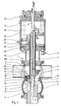
- the flap valve comprises a body 1 comprising a chamber 2 communicating with two lateral conduits 3.
- Two superimposed valves 4, 5 are movable in the chamber 2 along a common axis XX ′ perpendicular to the two lateral conduits 3.
- the lower part of the chamber 2 comprises a first seat 6 for the upper valve 4 and a second seat 7 disposed at a certain distance from the first seat 6, for the lower valve 5.
- the body 1 of the valve includes a second chamber 8 disposed under the two aforementioned seats 6, 7 into which opens a third conduit 9.
- the valves 4, 5 are each carried by a pendulum 10, 11 movable between a position in which the valve 4, 5 is sealingly supported on the corresponding seat 6, 7 (see left part of FIG. 1) and a position in which the valve is spaced from said seat (see right part of Figure 1).
- FIG. 1 also shows that the balance 11 of the lower valve 5 has an internal channel 12 which opens into a space 13 comprised between the two valves 4, 5.
- the space 13 between the two valves 4, 5 comprises a membrane 14 made of elastic material closing a chamber 15 into which opens an inlet 16 of pressurized air, so that the membrane 14 can swell and apply tightly to the lower valve 5 in order to seal the inlet of the channel 12 in a leaktight manner, as indicated on the right-hand side of FIG. 1.
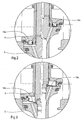
- the two ends of the membrane 14 carry heels 17, 18 embedded in grooves 19, 20.
- one 18 of the heels of the membrane 14 forms a seal between the balance 10 of the upper valve 4 and the balance 11 of the lower valve 5.
- one end of the membrane 14b, 14c, 14d is fixed to the balance 11 of the lower valve 5 near the upper surface thereof.
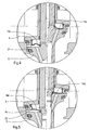
- the membrane 14c comprises a bead 21 bearing on the upper surface of the lower valve 5 when the membrane 14c is inflated by pressurized air.
- the bead 22 is adapted to be inserted in leaktight manner between the lower edge 4a of the upper valve 4 and the upper edge of the lower valve 5 when the membrane 14d is inflated by the air under pressure.
- FIG. 1 shows, on the other hand, that the inlet of pressurized air 16 which opens into the chamber 15 closed by the membrane 14 is connected to an axial channel 16a formed in the balance 11 of the lower valve 5.
- valves 4, 5 are kept in the closed position bearing on their corresponding seat 6, 7 by springs 23, 24 bearing on the upper ends of the pendulums 10, 11 of the valves 4, 5.
- the upper end of the balance 11 of the lower valve carries a piston 25 movable in a cylindrical chamber 26.
- a pressurized air inlet 27 is provided in a space 28 located under the piston 25 to move the latter towards the open position of the valves 4, 5.
- pressurized air is injected through the opening 25 which opens into the space 28.
- the pressurized air moves the piston 25 against the action of the spring 23.
- the displacement of the piston 25 drives the balance 11 of the lower valve 5.
- the balance 10 and the corresponding valve 4 follow the movement balance 11 and valve 5.
- the pressurized air injected into the space 28 enters the radial channel 16b, then into the channel 16a which opens into the chamber 15 through the conduit 16.
- the pressurized air by filling the chamber 15 causes the diaphragm 14 to swell, which therefore seals against the upper surface of the lower valve 5.
- the chamber 32 is closed by an elastic membrane 16e. Inside this chamber 32 is slidably housed a piston 33, one end 34 of which is in contact with the elastic membrane 16e.
- the supply of pressurized air 35 opens at the end of the chamber 32 opposite the membrane 16e.
- the piston 33 has a substantially U-shaped section, the base 34 in a U being in contact with the membrane 14e by a rounded surface which is spherical in the example shown.
- the piston 33 is preferably made of polytetrafluoroethylene.
- pressurized air enters the chamber 32.
- the pressurized air instead of acting directly on the membrane 14e, controls the displacement of the piston 33 which thus deforms the membrane 14e by pushing it towards the valve 5.
- the piston 33 acts as a pressure multiplier, to urge the membrane 14e under a pressure higher than that existing in the chamber 32 in the absence of the piston 33.
Landscapes
- Engineering & Computer Science (AREA)
- General Engineering & Computer Science (AREA)
- Mechanical Engineering (AREA)
- Check Valves (AREA)
- Fluid-Driven Valves (AREA)
- Reciprocating Pumps (AREA)
- Mattresses And Other Support Structures For Chairs And Beds (AREA)
- Air Bags (AREA)
- Air-Flow Control Members (AREA)
- Buffer Packaging (AREA)
Abstract
Description
L'invention concerne une vanne à double clapet.The invention relates to a double flap valve.
La demanderesse a créé une vanne à clapets comprenant un corps comportant une chambre communiquant avec deux conduits latéraux. Deux clapets superposés sont mobiles dans ladite chambre suivant un axe commun perpendiculaire aux deux conduits latéraux. La partie inférieure de la chambre comporte un premier siège pour le clapet supérieur et un deuxième siège disposé à une certaine distance sous le premier siège, pour le clapet inférieur.The Applicant has created a check valve comprising a body comprising a chamber communicating with two lateral conduits. Two superimposed valves are movable in said chamber along a common axis perpendicular to the two lateral conduits. The lower part of the chamber has a first seat for the upper valve and a second seat disposed at a certain distance under the first seat, for the lower valve.
Le corps de la vanne comporte une deuxième chambre disposée sous les deux sièges précités dans laquelle débouche un troisième conduit. Les clapets sont portés chacun par un balancier mobile entre une position dans laquelle le clapet prend appui de façon étanche sur le siège correspondant et une position dans laquelle le clapet est espacé dudit siège. Par ailleurs, le balancier du clapet inférieur comporte un canal interne qui débouche dans un espace compris entre les deux clapets.The valve body comprises a second chamber arranged under the two aforementioned seats into which a third conduit opens. The valves are each carried by a mobile pendulum between a position in which the valve bears in leaktight manner on the corresponding seat and a position in which the valve is spaced from said seat. Furthermore, the balance of the lower valve has an internal channel which opens into a space between the two valves.
Les deux clapets peuvent être déplacés indépendamment l'un de l'autre, en réalisant pour chacun d'eux un battement, lors du nettoyage de la vanne.The two valves can be moved independently of each other, providing a flapping for each of them, when cleaning the valve.
Le canal interne ménagé dans le balancier du clapet inférieur permet d'évacuer le liquide de nettoyage vers un collecteur.The internal channel formed in the balance of the lower valve makes it possible to evacuate the cleaning liquid towards a collector.
La vanne à clapets ci-dessus présente l'inconvénient suivant :The above flap valve has the following drawback:
Lorsque les deux clapets sont en position de fermeture en appui sur leur siège, il existe entre les deux sièges, un espace qui communique avec le canal ménagé dans le balancier du clapet inférieur.When the two valves are in the closed position bearing on their seat, there is between the two seats, a space which communicates with the channel formed in the balance of the lower valve.
Lors de l'ouverture des clapets, l'espace ci-dessus disparaît. Cependant, pendant un instant très court et avant que les clapets n'atteignent leur position d'ouverture complète, l'espace compris entre les deux clapets est mis en communication avec le canal précité.When the flaps open, the above space disappears. However, for a moment very short and before the valves reach their fully open position, the space between the two valves is placed in communication with the aforementioned channel.
Il en résulte ainsi une fuite du liquide traversant la vanne par le canal ci-dessus.This results in a leakage of the liquid passing through the valve through the above channel.
Le but de la présente invention est de remédier à l'inconvénient ci-dessus, en équipant la vanne d'un moyen permettant d'éviter toute fuite de liquide par le canal précité, lors du déplacement des clapets de leur position de fermeture vers leur position d'ouverture.The object of the present invention is to remedy the above drawback, by equipping the valve with means making it possible to avoid any leakage of liquid through the aforementioned channel, when the valves are moved from their closed position to their open position.
Suivant l'invention, cette vanne à clapets est caractérisée en ce que l'espace compris entre les deux clapets comprend une membrane en matière élastique fermant une chambre dans laquelle débouche une arrivée d'air sous pression, de telle sorte que la membrane puisse gonfler et s'appliquer de façon étanche sur le clapet inférieur pour obturer de façon étanche l'entrée dudit canal.According to the invention, this flap valve is characterized in that the space between the two flaps comprises a membrane of elastic material closing a chamber into which an inlet of pressurized air opens, so that the membrane can swell and apply sealingly on the lower valve to seal the inlet of said channel.
Ainsi, pour éviter toute fuite de liquide lors du déplacement des clapets vers la position d'ouverture, il suffit d'injecter de l'air sous pression dans la chambre comprise entre les deux clapets pour faire gonfler la membrane et réaliser l'étanchéité recherchée.Thus, to avoid any leakage of liquid during the movement of the valves towards the open position, it suffices to inject pressurized air into the chamber between the two valves to cause the membrane to swell and achieve the desired seal. .
Selon une version avantageuse de l'invention, ladite chambre fermée par la membrane élastique est ménagée dans la surface inférieure du clapet supérieur, au moins l'une des extrémités de la membrane étant fixée au clapet supérieur.According to an advantageous version of the invention, said chamber closed by the elastic membrane is formed in the lower surface of the upper valve, at least one of the ends of the membrane being fixed to the upper valve.
Selon une première version de l'invention, les deux extrémités de la membrane sont fixées au clapet supérieur.According to a first version of the invention, the two ends of the membrane are fixed to the upper valve.
Selon une autre version de l'invention, l'une des extrémités de la membrane est fixée au balancier du clapet inférieur près de la surface supérieure de celui-ci.According to another version of the invention, one end of the membrane is fixed to the balance of the lower valve near the upper surface thereof.
De préférence, l'arrivée d'air sous pression qui débouche dans ladite chambre fermée par la membrane est reliée à un canal axial ménagé dans le balancier du clapet inférieur.Preferably, the supply of pressurized air which opens into said chamber closed by the membrane is connected to an axial channel formed in the balance of the lower valve.
De préférence également, les clapets sont maintenus en position fermée en appui sur leur siège correspondant par des ressorts prenant appui sur les extrémités supérieures des balanciers desdits clapets, l'extrémité supérieure du balancier du clapet inférieur portant un piston mobile dans une chambre cylindrique, une arrivée d'air sous pression étant prévue dans un espace situé sous le piston pour déplacer celui-ci vers la position d'ouverture des clapets.Also preferably, the valves are held in the closed position bearing on their corresponding seat by springs bearing on the upper ends of the rockers of said valves, the upper end of the rocker of the lower valve carrying a movable piston in a cylindrical chamber, a pressurized air inlet being provided in a space located under the piston to move it to the open position of the valves.
D'autres particularités et avantages de l'invention apparaîtront encore dans la description ciaprès.Other features and advantages of the invention will become apparent in the description below.
Aux dessins annexés donnés à titre d'exemples non limitatifs :
- la figure 1 est une vue en coupe axiale d'une vanne à clapets selon l'invention équipée d'une première version de la membrane gonflable,
- la figure 2 est une vue en coupe axiale partielle, montrant une deuxième version de la membrane gonflable,
- la figure 3 est une vue en coupe axiale partielle, montrant une troisième version de la membrane gonflable,
- la figure 4 est une vue en coupe axiale partielle, montrant une quatrième version de la membrane gonflable,
- la figure 5 est une vue en coupe partielle, montrant une cinquième version de la membrane gonflable,
- la figure 6 est une vue en coupe partielle d'une version de la vanne à clapets selon l'invention équipée d'une membrane élastique sollicitée par un piston
- FIG. 1 is a view in axial section of a flap valve according to the invention equipped with a first version of the inflatable membrane,
- FIG. 2 is a partial axial section view showing a second version of the inflatable membrane,
- FIG. 3 is a partial axial section view showing a third version of the inflatable membrane,
- FIG. 4 is a partial axial section view showing a fourth version of the inflatable membrane,
- FIG. 5 is a partial section view showing a fifth version of the inflatable membrane,
- Figure 6 is a partial sectional view of a version of the flap valve according to the invention equipped with an elastic membrane biased by a piston
Dans la réalisation de la figure 1, la vanne à clapets comprend un corps 1 comportant une chambre 2 communiquant avec deux conduits latéraux 3.In the embodiment of FIG. 1, the flap valve comprises a
Deux clapets superposés 4, 5 sont mobiles dans la chambre 2 suivant un axe commun X-X' perpendiculaire aux deux conduits latéraux 3.Two
La partie inférieure de la chambre 2 comporte un premier siège 6 pour le clapet supérieur 4 et un deuxième siège 7 disposé à une certaine distance du premier siège 6, pour le clapet inférieur 5.The lower part of the
Par ailleurs, le corps 1 de la vanne comporte une deuxième chambre 8 disposée sous les deux sièges 6, 7 précités dans laquelle débouche un troisième conduit 9.Furthermore, the
Les clapets 4, 5 sont portés chacun par un balancier 10, 11 mobile entre une position dans laquelle le clapet 4, 5 prend appui de façon étanche sur le siège 6, 7 correspondant (voir partie gauche de la figure 1) et une position dans laquelle le clapet est espacé dudit siège (voir partie droite de la figure 1).The
La figure 1 montre d'autre part que le balancier 11 du clapet inférieur 5 comporte un canal interne 12 qui débouche dans un espace 13 compris entre les deux clapets 4, 5.FIG. 1 also shows that the
Conformément à l'invention, l'espace 13 compris entre les deux clapets 4, 5 comprend une membrane 14 en matière élastique fermant une chambre 15 dans laquelle débouche une arrivée 16 d'air sous pression, de telle sorte que la membrane 14 puisse gonfler et s'appliquer de façon étanche sur le clapet inférieur 5 pour obturer de façon étanche l'entrée du canal 12, comme indiqué sur la partie droite de la figure 1.According to the invention, the
On voit également sur la figure 1 que la chambre 15 fermée par la membrane élastique 14 est ménagée dans la surface inférieure du clapet supérieur 4 et que l'une des extrémités de la membrane 14 est fixée au clapet supérieur 4.It can also be seen in FIG. 1 that the
Par ailleurs, les deux extrémités de la membrane 14 portent des talons 17, 18 encastrés dans des gorges 19, 20.Furthermore, the two ends of the
Dans l'exemple des figures 1 et 2, les deux extrémités de la membrane 14, 14a sont fixées au clapet supérieur 4.In the example of FIGS. 1 and 2, the two ends of the
Dans l'exemple de la figure 1, l'un 18 des talons de la membrane 14 forme un joint d'étanchéité entre le balancier 10 du clapet supérieur 4 et le balancier 11 du clapet inférieur 5.In the example of FIG. 1, one 18 of the heels of the
Dans les exemples des figures 3, 4, 5, l'une des extrémités de la membrane 14b, 14c, 14d est fixée au balancier 11 du clapet inférieur 5 près de la surface supérieure de celui-ci.In the examples of Figures 3, 4, 5, one end of the
Dans l'exemple de la figure 4, la membrane 14c comporte un bourrelet 21 prenant appui sur la surface supérieure du clapet inférieur 5 lorsque la membrane 14c est gonflée par l'air sous pression.In the example of FIG. 4, the
Dans l'exemple de la figure 5, le bourrelet 22 est adapté pour venir s'insérer de façon étanche entre le bord inférieur 4a du clapet supérieur 4 et le bord supérieur du clapet inférieur 5 lorsque la membrane 14d est gonflée par l'air sous pression.In the example of FIG. 5, the
La figure 1 montre, d'autre part, que l'arrivée d'air sous pression 16 qui débouche dans la chambre 15 fermée par la membrane 14 est reliée à un canal axial 16a ménagé dans le balancier 11 du clapet inférieur 5.FIG. 1 shows, on the other hand, that the inlet of
Par ailleurs, les clapets 4, 5 sont maintenus en position fermée en appui sur leur siège correspondant 6, 7 par des ressorts 23, 24 prenant appui sur les extrémités supérieures des balanciers 10, 11 des clapets 4, 5.Furthermore, the
L'extrémité supérieure du balancier 11 du clapet inférieur porte un piston 25 mobile dans une chambre cylindrique 26.The upper end of the
Une arrivée d'air sous pression 27 est prévue dans un espace 28 situé sous le piston 25 pour déplacer celui-ci vers la position d'ouverture des clapets 4, 5.A pressurized
On voit également sur la figure 1, que le canal axial 16a ménagé dans le balancier 11 du clapet inférieur 5 débouche à l'extrémité supérieure de ce balancier dans l'espace 28 dans lequel débouche l'arrivée d'air sous pression 27.It can also be seen in FIG. 1 that the
Ainsi, lorsque l'air sous pression commande le déplacement du piston 25 vers la position d'ouverture des clapets 4, 5, l'air sous pression pénètre dans le canal 16a, puis dans la chambre 15 et gonfle la membrane 14.Thus, when the pressurized air controls the displacement of the
On va maintenant expliquer le fonctionnement de la vanne à clapets que l'on vient de décrire.We will now explain the operation of the reed valve that has just been described.
Pour commander l'ouverture des clapets 4, 5, on injecte de l'air sous pression par l'ouverture 25 qui débouche dans l'espace 28.To control the opening of the
L'air sous pression déplace le piston 25 contre l'action du ressort 23. Le déplacement du piston 25 entraîne le balancier 11 du clapet inférieur 5. Sous l'effet du ressort 24, le balancier 10 et le clapet correspondant 4 suivent le déplacement du balancier 11 et du clapet 5.The pressurized air moves the
L'air sous pression injecté dans l'espace 28 pénètre dans le canal radial 16b, puis dans le canal 16a qui débouche dans la chambre 15 grâce au conduit 16.The pressurized air injected into the
L'air sous pression en remplissant la chambre 15 provoque le gonflement de la membrane 14 qui de ce fait s'appuie de façon étanche sur la surface supérieure du clapet inférieur 5.The pressurized air by filling the
Ainsi, aucune fuite de produit ne peut avoir lieu par le canal 12, lors du déplacement des clapets 4, 5 vers leur position d'ouverture.Thus, no product leakage can take place through the
Pour nettoyer les joints des clapets 4, 5, il est possible de réaliser un battement de ces clapets sur leur siège 6, 7.To clean the seals of the
Ainsi pour réaliser le battement du clapet inférieur 5, il suffit d'insuffler de l'air sous pression dans l'ouverture 29, ce qui provoque le déplacement du piston 30 qui entraîne le balancier 11 du clapet 5.Thus, to effect the flapping of the
De même, pour réaliser le battement du clapet supérieur 4, il suffit d'insuffler de l'air sous pression dans l'ouverture 31, ce qui provoque le déplacement du piston 32 qui entraîne le balancier 10 du clapet 4.Likewise, to effect the flapping of the
Dans la réalisation de la figure 6, la chambre 32 est fermée par une membrane élastique 16e. A l'intérieur de cette chambre 32 est logé de façon coulissante un piston 33 dont une extrémité 34 est en contact avec la membrane élastique 16e.In the embodiment of FIG. 6, the
L'arrivée d'air sous pression 35 débouche à l'extrémité de la chambre 32 opposée à la membrane 16e.The supply of
Comme montré par la figure 6, le piston 33 a une section sensiblement en U, la base 34 en U étant en contact avec la membrane 14e par une surface arrondie qui est sphérique dans l'exemple représenté.As shown in Figure 6, the
Le piston 33 est de préférence en polytétrafluoréthylène.The
Le fonctionnement de la vanne à clapets selon la figure 6 est identique à celle selon la figure 1.The operation of the flap valve according to FIG. 6 is identical to that according to FIG. 1.
Lors de l'ouverture des clapets 4, 5, de l'air sous pression arrive dans la chambre 32. Toutefois, l'air sous pression, au lieu d'agir directement sur la membrane 14e, commande le déplacement du piston 33 qui de ce fait déforme la membrane 14e en la poussant vers le clapet 5.When the
Du fait de sa forme, le piston 33 agit comme un multiplicateur de pression, pour solliciter la membrane 14e sous une pression supérieure à celle existant dans la chambre 32 en l'absence du piston 33.Because of its shape, the
Il en résulte une amélioration de l'étanchéité entre les clapets 4 et 5.This results in an improvement in the seal between the
Bien entendu, l'invention n'est pas limitée à l'exemple que l'on vient de décrire et on peut apporter à celui-ci de nombreuses modifications sans sortir du cadre de l'invention.Of course, the invention is not limited to the example which has just been described and many modifications can be made to it without departing from the scope of the invention.
Claims (15)
Priority Applications (1)
| Application Number | Priority Date | Filing Date | Title |
|---|---|---|---|
| DK99400826T DK0952376T3 (en) | 1998-04-21 | 1999-04-02 | Double seat valve with playable diaphragm |
Applications Claiming Priority (4)
| Application Number | Priority Date | Filing Date | Title |
|---|---|---|---|
| FR9804974A FR2777625A1 (en) | 1998-04-21 | 1998-04-21 | Valve with two shutters controlling fluid flow |
| FR9804974 | 1998-04-21 | ||
| FR9808330 | 1998-06-30 | ||
| FR9808330A FR2777626B1 (en) | 1998-04-21 | 1998-06-30 | VALVE WITH VALVES AND INFLATABLE MEMBRANE |
Publications (2)
| Publication Number | Publication Date |
|---|---|
| EP0952376A1 true EP0952376A1 (en) | 1999-10-27 |
| EP0952376B1 EP0952376B1 (en) | 2004-10-20 |
Family
ID=26234281
Family Applications (1)
| Application Number | Title | Priority Date | Filing Date |
|---|---|---|---|
| EP19990400826 Expired - Lifetime EP0952376B1 (en) | 1998-04-21 | 1999-04-02 | Double-seat lift valve with inflatable membrane |
Country Status (7)
| Country | Link |
|---|---|
| US (1) | US6089255A (en) |
| EP (1) | EP0952376B1 (en) |
| AT (1) | ATE280345T1 (en) |
| CA (1) | CA2269037C (en) |
| DE (1) | DE69921224T2 (en) |
| DK (1) | DK0952376T3 (en) |
| FR (1) | FR2777626B1 (en) |
Cited By (4)
| Publication number | Priority date | Publication date | Assignee | Title |
|---|---|---|---|---|
| EP1903264A1 (en) * | 2006-09-25 | 2008-03-26 | Gebr. Rieger GmbH & Co. KG | Double-seat valve device |
| WO2009003994A1 (en) * | 2007-07-02 | 2009-01-08 | Luxembourg Patent Company S.A. | Shutoff valve integrated into a pressure regulator |
| CN101956871A (en) * | 2010-06-08 | 2011-01-26 | 昆山新莱洁净应用材料股份有限公司 | Reciprocating valve rod steam sterilization device |
| CN104220796A (en) * | 2012-02-03 | 2014-12-17 | 基伊埃图亨哈根有限公司 | Method for cleaning the seat of a double seat valve and double seat valve for performing the method |
Families Citing this family (13)
| Publication number | Priority date | Publication date | Assignee | Title |
|---|---|---|---|---|
| DE19750300A1 (en) * | 1997-11-13 | 1999-06-02 | Alfa Laval Lkm A S | Double seat valve |
| GB9819835D0 (en) * | 1998-09-12 | 1998-11-04 | Hygienic Pigging Systems Limit | Valves |
| FR2800297B1 (en) * | 1999-10-28 | 2001-12-28 | Air Liquide | CYCLIC FLUID TREATMENT SYSTEM BY ADSORPTION WITH IMPROVED SEALING VALVES |
| US6637723B1 (en) | 2001-09-06 | 2003-10-28 | Entegris, Inc. | Fluid valve |
| US6935616B2 (en) * | 2003-07-18 | 2005-08-30 | Hans D. Baumann | Balanced plug valve |
| US7234678B1 (en) * | 2003-09-22 | 2007-06-26 | Kabushiki Kaisha Toshiba | Protection system for turbo machine and power generating equipment |
| NZ533910A (en) * | 2004-07-05 | 2007-02-23 | Tyco Flow Control Pacific Pty | Valve status monitoring |
| DE102004051575B4 (en) * | 2004-10-22 | 2015-12-17 | Bosch Rexroth Aktiengesellschaft | Directional seated valve |
| AU2006312793A1 (en) * | 2005-11-12 | 2007-05-18 | Tuchenhagen Gmbh | Double seat valve |
| DE202008003976U1 (en) * | 2008-03-20 | 2008-11-27 | Gea Tuchenhagen Gmbh | Seat-cleaning double-seat valve with a cleaning device for a rod feed-through |
| US8327881B2 (en) * | 2008-09-19 | 2012-12-11 | Spx Corporation | Double seat valve apparatus |
| DE102012107992A1 (en) * | 2012-08-29 | 2014-03-06 | Südmo Holding GmbH | Aseptic double-seat valve |
| EP4093997A1 (en) * | 2020-01-24 | 2022-11-30 | GEA Tuchenhagen GmbH | Valve and cleaning method |
Citations (4)
| Publication number | Priority date | Publication date | Assignee | Title |
|---|---|---|---|---|
| DE2818787A1 (en) * | 1978-04-28 | 1979-11-08 | Holstein & Kappert Maschf | Double seated valve operation control system - presses auxiliary valve plate against second main one before opening first |
| GB2064724A (en) * | 1979-11-20 | 1981-06-17 | Jeppsson E H O | Valve |
| DE3017084A1 (en) * | 1980-05-03 | 1981-11-05 | Gea Ahlborn Gmbh & Co Kg, 3203 Sarstedt | Double seated fluid stop valve - has diaphragm shutting leakage chamber off from atmosphere before opening |
| EP0545846A1 (en) * | 1991-11-29 | 1993-06-09 | Hakan Jeppsson | Double-seat valves |
Family Cites Families (4)
| Publication number | Priority date | Publication date | Assignee | Title |
|---|---|---|---|---|
| US2705016A (en) * | 1952-10-28 | 1955-03-29 | Pratt Co Henry | Butterfly valve |
| DE2837298C2 (en) * | 1978-08-26 | 1984-05-24 | Holstein Und Kappert Gmbh, 4600 Dortmund | Double seat lift valve |
| US4292992A (en) * | 1979-07-23 | 1981-10-06 | Allis-Chalmers Corporation | Valve for handling solids capable of gas-pressure-tight closure against a gas pressure differential |
| DE3224852A1 (en) * | 1982-07-02 | 1984-01-05 | Albert Handtmann Armaturenfabrik GmbH & Co KG, 7950 Biberach | DOUBLE SEAT VALVE |
-
1998
- 1998-06-30 FR FR9808330A patent/FR2777626B1/en not_active Expired - Lifetime
-
1999
- 1999-04-02 AT AT99400826T patent/ATE280345T1/en not_active IP Right Cessation
- 1999-04-02 DK DK99400826T patent/DK0952376T3/en active
- 1999-04-02 DE DE1999621224 patent/DE69921224T2/en not_active Expired - Lifetime
- 1999-04-02 EP EP19990400826 patent/EP0952376B1/en not_active Expired - Lifetime
- 1999-04-14 CA CA 2269037 patent/CA2269037C/en not_active Expired - Lifetime
- 1999-04-19 US US09/294,673 patent/US6089255A/en not_active Expired - Lifetime
Patent Citations (4)
| Publication number | Priority date | Publication date | Assignee | Title |
|---|---|---|---|---|
| DE2818787A1 (en) * | 1978-04-28 | 1979-11-08 | Holstein & Kappert Maschf | Double seated valve operation control system - presses auxiliary valve plate against second main one before opening first |
| GB2064724A (en) * | 1979-11-20 | 1981-06-17 | Jeppsson E H O | Valve |
| DE3017084A1 (en) * | 1980-05-03 | 1981-11-05 | Gea Ahlborn Gmbh & Co Kg, 3203 Sarstedt | Double seated fluid stop valve - has diaphragm shutting leakage chamber off from atmosphere before opening |
| EP0545846A1 (en) * | 1991-11-29 | 1993-06-09 | Hakan Jeppsson | Double-seat valves |
Cited By (7)
| Publication number | Priority date | Publication date | Assignee | Title |
|---|---|---|---|---|
| EP1903264A1 (en) * | 2006-09-25 | 2008-03-26 | Gebr. Rieger GmbH & Co. KG | Double-seat valve device |
| WO2009003994A1 (en) * | 2007-07-02 | 2009-01-08 | Luxembourg Patent Company S.A. | Shutoff valve integrated into a pressure regulator |
| EP2017514A1 (en) * | 2007-07-02 | 2009-01-21 | Luxembourg Patent Company S.A. | Closing valve integrated into a pressure-reducing valve |
| KR101499042B1 (en) * | 2007-07-02 | 2015-03-05 | 룩셈부르크 패턴트 컴퍼니 에스.에이. | Shutoff valve integrated into a pressure regulator |
| CN101956871A (en) * | 2010-06-08 | 2011-01-26 | 昆山新莱洁净应用材料股份有限公司 | Reciprocating valve rod steam sterilization device |
| CN104220796A (en) * | 2012-02-03 | 2014-12-17 | 基伊埃图亨哈根有限公司 | Method for cleaning the seat of a double seat valve and double seat valve for performing the method |
| CN104220796B (en) * | 2012-02-03 | 2017-03-08 | 基伊埃图亨哈根有限公司 | The method cleaned for the seat of double-beat drop valve and the double-beat drop valve for implementing methods described |
Also Published As
| Publication number | Publication date |
|---|---|
| DE69921224T2 (en) | 2005-10-27 |
| DK0952376T3 (en) | 2004-11-15 |
| US6089255A (en) | 2000-07-18 |
| FR2777626B1 (en) | 2000-05-26 |
| ATE280345T1 (en) | 2004-11-15 |
| DE69921224D1 (en) | 2004-11-25 |
| EP0952376B1 (en) | 2004-10-20 |
| CA2269037A1 (en) | 1999-10-21 |
| FR2777626A1 (en) | 1999-10-22 |
| CA2269037C (en) | 2007-03-27 |
Similar Documents
| Publication | Publication Date | Title |
|---|---|---|
| EP0952376A1 (en) | Double-seat lift valve with inflatable membrane | |
| FR2688857A1 (en) | VALVE COMPRISING A TILTING SHUTTER AND AN INSULATION MEMBRANE. | |
| EP0148480A2 (en) | Valve opened by vacuum | |
| FR2502475A1 (en) | SUPPORT DEVICE FOR PIVOT CHAIR | |
| CH626144A5 (en) | ||
| EP0511135B1 (en) | Pneumatic regulation device for the automatic inflation/deflation and the measurement of pressure within a closed volume of gaseous fluid under relative pressure (e.g. a tyre) | |
| EP1165426B1 (en) | Device for filling receptacles fitted with an integrated cleaning device | |
| FR2772446A1 (en) | GAS SPRING | |
| EP0246584B1 (en) | Valve with membrane | |
| EP0669222B1 (en) | Height adjustable armrest for automotive vehicles | |
| FR2564558A1 (en) | SPHERICAL TURNING BOOM TAP | |
| FR2652426A1 (en) | GAS BOTTLE REGULATOR. | |
| FR2557950A1 (en) | IMPROVEMENTS ON PISTON-CONTROLLED VALVES | |
| FR2727734A1 (en) | Control valve with two flow characteristic, used in industrial and heating purposes | |
| FR2777625A1 (en) | Valve with two shutters controlling fluid flow | |
| FR2619432A1 (en) | Tap for a bottle of pressurised gas | |
| FR2625284A1 (en) | Valve for regulating the pressure inside a fuel tank | |
| EP0516528B1 (en) | Safety valve for the ventilation of a fuel tank of a motor vehicle | |
| FR2558562A1 (en) | Pilot-controlled pneumatic valve. | |
| FR2509827A1 (en) | PRESSURE CONTROL VALVE | |
| EP0013656B1 (en) | Double acting pneumatic serateurs | |
| FR2915786A1 (en) | Blocker type connection for connecting actuator e.g. jack, has flap valve connected to piston sling along central axis in piloting chamber, and burging unit arranged on channel of side of seat oriented toward one of joining units | |
| EP0719686B1 (en) | Pressure reducing valve and brake valve utilizing same | |
| FR2570469A1 (en) | Device for filling butane and propane gas bottles | |
| BE1005079A3 (en) | Pouring stopper |
Legal Events
| Date | Code | Title | Description |
|---|---|---|---|
| PUAI | Public reference made under article 153(3) epc to a published international application that has entered the european phase |
Free format text: ORIGINAL CODE: 0009012 |
|
| AK | Designated contracting states |
Kind code of ref document: A1 Designated state(s): AT BE CH DE DK ES GB IE IT LI LU NL SE |
|
| AX | Request for extension of the european patent |
Free format text: AL;LT;LV;MK;RO;SI |
|
| 17P | Request for examination filed |
Effective date: 20000211 |
|
| AKX | Designation fees paid |
Free format text: AT BE CH DE DK ES GB IE IT LI LU NL SE |
|
| RIN1 | Information on inventor provided before grant (corrected) |
Inventor name: PICOT, THIERRY Inventor name: MARAUD, BRUNO Inventor name: BONNEFOUS, JEAN |
|
| 17Q | First examination report despatched |
Effective date: 20030526 |
|
| GRAP | Despatch of communication of intention to grant a patent |
Free format text: ORIGINAL CODE: EPIDOSNIGR1 |
|
| GRAS | Grant fee paid |
Free format text: ORIGINAL CODE: EPIDOSNIGR3 |
|
| GRAA | (expected) grant |
Free format text: ORIGINAL CODE: 0009210 |
|
| RAP1 | Party data changed (applicant data changed or rights of an application transferred) |
Owner name: S.A. DEFONTAINE |
|
| AK | Designated contracting states |
Kind code of ref document: B1 Designated state(s): AT BE CH DE DK ES GB IE IT LI LU NL SE |
|
| PG25 | Lapsed in a contracting state [announced via postgrant information from national office to epo] |
Ref country code: NL Free format text: LAPSE BECAUSE OF FAILURE TO SUBMIT A TRANSLATION OF THE DESCRIPTION OR TO PAY THE FEE WITHIN THE PRESCRIBED TIME-LIMIT Effective date: 20041020 Ref country code: IT Free format text: LAPSE BECAUSE OF FAILURE TO SUBMIT A TRANSLATION OF THE DESCRIPTION OR TO PAY THE FEE WITHIN THE PRE;WARNING: LAPSES OF ITALIAN PATENTS WITH EFFECTIVE DATE BEFORE 2007 MAY HAVE OCCURRED AT ANY TIME BEFORE 2007. THE CORRECT EFFECTIVE DATE MAY BE DIFFERENT FROM THE ONE RECORDED.SCRIBED TIME-LIMIT Effective date: 20041020 Ref country code: IE Free format text: LAPSE BECAUSE OF FAILURE TO SUBMIT A TRANSLATION OF THE DESCRIPTION OR TO PAY THE FEE WITHIN THE PRESCRIBED TIME-LIMIT Effective date: 20041020 Ref country code: GB Free format text: LAPSE BECAUSE OF FAILURE TO SUBMIT A TRANSLATION OF THE DESCRIPTION OR TO PAY THE FEE WITHIN THE PRESCRIBED TIME-LIMIT Effective date: 20041020 Ref country code: AT Free format text: LAPSE BECAUSE OF FAILURE TO SUBMIT A TRANSLATION OF THE DESCRIPTION OR TO PAY THE FEE WITHIN THE PRESCRIBED TIME-LIMIT Effective date: 20041020 |
|
| REG | Reference to a national code |
Ref country code: GB Ref legal event code: FG4D Free format text: NOT ENGLISH |
|
| REG | Reference to a national code |
Ref country code: CH Ref legal event code: EP |
|
| REG | Reference to a national code |
Ref country code: DK Ref legal event code: T3 |
|
| REG | Reference to a national code |
Ref country code: IE Ref legal event code: FG4D Free format text: FRENCH |
|
| REF | Corresponds to: |
Ref document number: 69921224 Country of ref document: DE Date of ref document: 20041125 Kind code of ref document: P |
|
| PG25 | Lapsed in a contracting state [announced via postgrant information from national office to epo] |
Ref country code: SE Free format text: LAPSE BECAUSE OF FAILURE TO SUBMIT A TRANSLATION OF THE DESCRIPTION OR TO PAY THE FEE WITHIN THE PRESCRIBED TIME-LIMIT Effective date: 20050120 |
|
| PG25 | Lapsed in a contracting state [announced via postgrant information from national office to epo] |
Ref country code: ES Free format text: LAPSE BECAUSE OF FAILURE TO SUBMIT A TRANSLATION OF THE DESCRIPTION OR TO PAY THE FEE WITHIN THE PRESCRIBED TIME-LIMIT Effective date: 20050131 |
|
| PG25 | Lapsed in a contracting state [announced via postgrant information from national office to epo] |
Ref country code: LU Free format text: LAPSE BECAUSE OF NON-PAYMENT OF DUE FEES Effective date: 20050402 |
|
| PG25 | Lapsed in a contracting state [announced via postgrant information from national office to epo] |
Ref country code: LI Free format text: LAPSE BECAUSE OF NON-PAYMENT OF DUE FEES Effective date: 20050430 Ref country code: CH Free format text: LAPSE BECAUSE OF NON-PAYMENT OF DUE FEES Effective date: 20050430 Ref country code: BE Free format text: LAPSE BECAUSE OF NON-PAYMENT OF DUE FEES Effective date: 20050430 |
|
| NLV1 | Nl: lapsed or annulled due to failure to fulfill the requirements of art. 29p and 29m of the patents act | ||
| GBV | Gb: ep patent (uk) treated as always having been void in accordance with gb section 77(7)/1977 [no translation filed] |
Effective date: 20041020 |
|
| REG | Reference to a national code |
Ref country code: IE Ref legal event code: FD4D |
|
| PLBE | No opposition filed within time limit |
Free format text: ORIGINAL CODE: 0009261 |
|
| STAA | Information on the status of an ep patent application or granted ep patent |
Free format text: STATUS: NO OPPOSITION FILED WITHIN TIME LIMIT |
|
| 26N | No opposition filed |
Effective date: 20050721 |
|
| BERE | Be: lapsed |
Owner name: S.A. DEFONTAINE Effective date: 20050430 |
|
| REG | Reference to a national code |
Ref country code: CH Ref legal event code: PL |
|
| BERE | Be: lapsed |
Owner name: S.A. *DEFONTAINE Effective date: 20050430 |
|
| REG | Reference to a national code |
Ref country code: DE Ref legal event code: R082 Ref document number: 69921224 Country of ref document: DE Representative=s name: RAU, SCHNECK & HUEBNER PATENT- UND RECHTSANWAE, DE |
|
| REG | Reference to a national code |
Ref country code: DE Ref legal event code: R082 Ref document number: 69921224 Country of ref document: DE Representative=s name: RAU, SCHNECK & HUEBNER PATENTANWAELTE RECHTSAN, DE Effective date: 20120102 Ref country code: DE Ref legal event code: R081 Ref document number: 69921224 Country of ref document: DE Owner name: DEFINOX SAS, FR Free format text: FORMER OWNER: S.A. DEFONTAINE, LA BRUFFIERE, FR Effective date: 20120102 |
|
| PGFP | Annual fee paid to national office [announced via postgrant information from national office to epo] |
Ref country code: DK Payment date: 20180410 Year of fee payment: 20 Ref country code: DE Payment date: 20180320 Year of fee payment: 20 |
|
| REG | Reference to a national code |
Ref country code: DE Ref legal event code: R071 Ref document number: 69921224 Country of ref document: DE |
|
| REG | Reference to a national code |
Ref country code: DK Ref legal event code: EUP Effective date: 20190402 |