EP0952376A1 - Doppelsitzventil mit aufblasbarer Membran - Google Patents
Doppelsitzventil mit aufblasbarer Membran Download PDFInfo
- Publication number
- EP0952376A1 EP0952376A1 EP19990400826 EP99400826A EP0952376A1 EP 0952376 A1 EP0952376 A1 EP 0952376A1 EP 19990400826 EP19990400826 EP 19990400826 EP 99400826 A EP99400826 A EP 99400826A EP 0952376 A1 EP0952376 A1 EP 0952376A1
- Authority
- EP
- European Patent Office
- Prior art keywords
- valve
- membrane
- chamber
- valves
- pressurized air
- Prior art date
- Legal status (The legal status is an assumption and is not a legal conclusion. Google has not performed a legal analysis and makes no representation as to the accuracy of the status listed.)
- Granted
Links
Images

Classifications
-
- F—MECHANICAL ENGINEERING; LIGHTING; HEATING; WEAPONS; BLASTING
- F16—ENGINEERING ELEMENTS AND UNITS; GENERAL MEASURES FOR PRODUCING AND MAINTAINING EFFECTIVE FUNCTIONING OF MACHINES OR INSTALLATIONS; THERMAL INSULATION IN GENERAL
- F16K—VALVES; TAPS; COCKS; ACTUATING-FLOATS; DEVICES FOR VENTING OR AERATING
- F16K1/00—Lift valves or globe valves, i.e. cut-off apparatus with closure members having at least a component of their opening and closing motion perpendicular to the closing faces
- F16K1/32—Details
- F16K1/34—Cutting-off parts, e.g. valve members, seats
- F16K1/44—Details of seats or valve members of double-seat valves
- F16K1/443—Details of seats or valve members of double-seat valves the seats being in series
- F16K1/446—Details of seats or valve members of double-seat valves the seats being in series with additional cleaning or venting means between the two seats
-
- Y—GENERAL TAGGING OF NEW TECHNOLOGICAL DEVELOPMENTS; GENERAL TAGGING OF CROSS-SECTIONAL TECHNOLOGIES SPANNING OVER SEVERAL SECTIONS OF THE IPC; TECHNICAL SUBJECTS COVERED BY FORMER USPC CROSS-REFERENCE ART COLLECTIONS [XRACs] AND DIGESTS
- Y10—TECHNICAL SUBJECTS COVERED BY FORMER USPC
- Y10T—TECHNICAL SUBJECTS COVERED BY FORMER US CLASSIFICATION
- Y10T137/00—Fluid handling
- Y10T137/4238—With cleaner, lubrication added to fluid or liquid sealing at valve interface
- Y10T137/4245—Cleaning or steam sterilizing
- Y10T137/4259—With separate material addition
-
- Y—GENERAL TAGGING OF NEW TECHNOLOGICAL DEVELOPMENTS; GENERAL TAGGING OF CROSS-SECTIONAL TECHNOLOGIES SPANNING OVER SEVERAL SECTIONS OF THE IPC; TECHNICAL SUBJECTS COVERED BY FORMER USPC CROSS-REFERENCE ART COLLECTIONS [XRACs] AND DIGESTS
- Y10—TECHNICAL SUBJECTS COVERED BY FORMER USPC
- Y10T—TECHNICAL SUBJECTS COVERED BY FORMER US CLASSIFICATION
- Y10T137/00—Fluid handling
- Y10T137/5762—With leakage or drip collecting
-
- Y—GENERAL TAGGING OF NEW TECHNOLOGICAL DEVELOPMENTS; GENERAL TAGGING OF CROSS-SECTIONAL TECHNOLOGIES SPANNING OVER SEVERAL SECTIONS OF THE IPC; TECHNICAL SUBJECTS COVERED BY FORMER USPC CROSS-REFERENCE ART COLLECTIONS [XRACs] AND DIGESTS
- Y10—TECHNICAL SUBJECTS COVERED BY FORMER USPC
- Y10T—TECHNICAL SUBJECTS COVERED BY FORMER US CLASSIFICATION
- Y10T137/00—Fluid handling
- Y10T137/8593—Systems
- Y10T137/87917—Flow path with serial valves and/or closures
- Y10T137/88038—One valve head carries other valve head
Definitions
- the invention relates to a double flap valve.
- the Applicant has created a check valve comprising a body comprising a chamber communicating with two lateral conduits. Two superimposed valves are movable in said chamber along a common axis perpendicular to the two lateral conduits.
- the lower part of the chamber has a first seat for the upper valve and a second seat disposed at a certain distance under the first seat, for the lower valve.
- the valve body comprises a second chamber arranged under the two aforementioned seats into which a third conduit opens.
- the valves are each carried by a mobile pendulum between a position in which the valve bears in leaktight manner on the corresponding seat and a position in which the valve is spaced from said seat. Furthermore, the balance of the lower valve has an internal channel which opens into a space between the two valves.
- the two valves can be moved independently of each other, providing a flapping for each of them, when cleaning the valve.
- the internal channel formed in the balance of the lower valve makes it possible to evacuate the cleaning liquid towards a collector.
- the above flap valve has the following drawback:
- the object of the present invention is to remedy the above drawback, by equipping the valve with means making it possible to avoid any leakage of liquid through the aforementioned channel, when the valves are moved from their closed position to their open position.
- this flap valve is characterized in that the space between the two flaps comprises a membrane of elastic material closing a chamber into which an inlet of pressurized air opens, so that the membrane can swell and apply sealingly on the lower valve to seal the inlet of said channel.
- said chamber closed by the elastic membrane is formed in the lower surface of the upper valve, at least one of the ends of the membrane being fixed to the upper valve.
- the two ends of the membrane are fixed to the upper valve.
- one end of the membrane is fixed to the balance of the lower valve near the upper surface thereof.
- the supply of pressurized air which opens into said chamber closed by the membrane is connected to an axial channel formed in the balance of the lower valve.
- valves are held in the closed position bearing on their corresponding seat by springs bearing on the upper ends of the rockers of said valves, the upper end of the rocker of the lower valve carrying a movable piston in a cylindrical chamber, a pressurized air inlet being provided in a space located under the piston to move it to the open position of the valves.
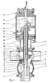
- the flap valve comprises a body 1 comprising a chamber 2 communicating with two lateral conduits 3.
- Two superimposed valves 4, 5 are movable in the chamber 2 along a common axis XX ′ perpendicular to the two lateral conduits 3.
- the lower part of the chamber 2 comprises a first seat 6 for the upper valve 4 and a second seat 7 disposed at a certain distance from the first seat 6, for the lower valve 5.
- the body 1 of the valve includes a second chamber 8 disposed under the two aforementioned seats 6, 7 into which opens a third conduit 9.
- the valves 4, 5 are each carried by a pendulum 10, 11 movable between a position in which the valve 4, 5 is sealingly supported on the corresponding seat 6, 7 (see left part of FIG. 1) and a position in which the valve is spaced from said seat (see right part of Figure 1).
- FIG. 1 also shows that the balance 11 of the lower valve 5 has an internal channel 12 which opens into a space 13 comprised between the two valves 4, 5.
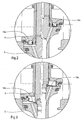
- the space 13 between the two valves 4, 5 comprises a membrane 14 made of elastic material closing a chamber 15 into which opens an inlet 16 of pressurized air, so that the membrane 14 can swell and apply tightly to the lower valve 5 in order to seal the inlet of the channel 12 in a leaktight manner, as indicated on the right-hand side of FIG. 1.
- the two ends of the membrane 14 carry heels 17, 18 embedded in grooves 19, 20.
- one 18 of the heels of the membrane 14 forms a seal between the balance 10 of the upper valve 4 and the balance 11 of the lower valve 5.
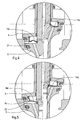
- one end of the membrane 14b, 14c, 14d is fixed to the balance 11 of the lower valve 5 near the upper surface thereof.
- the membrane 14c comprises a bead 21 bearing on the upper surface of the lower valve 5 when the membrane 14c is inflated by pressurized air.
- the bead 22 is adapted to be inserted in leaktight manner between the lower edge 4a of the upper valve 4 and the upper edge of the lower valve 5 when the membrane 14d is inflated by the air under pressure.
- FIG. 1 shows, on the other hand, that the inlet of pressurized air 16 which opens into the chamber 15 closed by the membrane 14 is connected to an axial channel 16a formed in the balance 11 of the lower valve 5.
- valves 4, 5 are kept in the closed position bearing on their corresponding seat 6, 7 by springs 23, 24 bearing on the upper ends of the pendulums 10, 11 of the valves 4, 5.
- the upper end of the balance 11 of the lower valve carries a piston 25 movable in a cylindrical chamber 26.
- a pressurized air inlet 27 is provided in a space 28 located under the piston 25 to move the latter towards the open position of the valves 4, 5.
- pressurized air is injected through the opening 25 which opens into the space 28.
- the pressurized air moves the piston 25 against the action of the spring 23.
- the displacement of the piston 25 drives the balance 11 of the lower valve 5.
- the balance 10 and the corresponding valve 4 follow the movement balance 11 and valve 5.
- the pressurized air injected into the space 28 enters the radial channel 16b, then into the channel 16a which opens into the chamber 15 through the conduit 16.
- the pressurized air by filling the chamber 15 causes the diaphragm 14 to swell, which therefore seals against the upper surface of the lower valve 5.
- the chamber 32 is closed by an elastic membrane 16e. Inside this chamber 32 is slidably housed a piston 33, one end 34 of which is in contact with the elastic membrane 16e.
- the supply of pressurized air 35 opens at the end of the chamber 32 opposite the membrane 16e.
- the piston 33 has a substantially U-shaped section, the base 34 in a U being in contact with the membrane 14e by a rounded surface which is spherical in the example shown.
- the piston 33 is preferably made of polytetrafluoroethylene.
- pressurized air enters the chamber 32.
- the pressurized air instead of acting directly on the membrane 14e, controls the displacement of the piston 33 which thus deforms the membrane 14e by pushing it towards the valve 5.
- the piston 33 acts as a pressure multiplier, to urge the membrane 14e under a pressure higher than that existing in the chamber 32 in the absence of the piston 33.
Priority Applications (1)
| Application Number | Priority Date | Filing Date | Title |
|---|---|---|---|
| DK99400826T DK0952376T3 (da) | 1998-04-21 | 1999-04-02 | Dobbeltsædet ventil med udspilelig membran |
Applications Claiming Priority (4)
| Application Number | Priority Date | Filing Date | Title |
|---|---|---|---|
| FR9804974A FR2777625A1 (fr) | 1998-04-21 | 1998-04-21 | Vanne a clapets et membrane gonflable |
| FR9804974 | 1998-04-21 | ||
| FR9808330 | 1998-06-30 | ||
| FR9808330A FR2777626B1 (fr) | 1998-04-21 | 1998-06-30 | Vanne a clapets et membrane gonflable |
Publications (2)
| Publication Number | Publication Date |
|---|---|
| EP0952376A1 true EP0952376A1 (de) | 1999-10-27 |
| EP0952376B1 EP0952376B1 (de) | 2004-10-20 |
Family
ID=26234281
Family Applications (1)
| Application Number | Title | Priority Date | Filing Date |
|---|---|---|---|
| EP19990400826 Expired - Lifetime EP0952376B1 (de) | 1998-04-21 | 1999-04-02 | Doppelsitzventil mit aufblasbarer Membran |
Country Status (7)
| Country | Link |
|---|---|
| US (1) | US6089255A (de) |
| EP (1) | EP0952376B1 (de) |
| AT (1) | ATE280345T1 (de) |
| CA (1) | CA2269037C (de) |
| DE (1) | DE69921224T2 (de) |
| DK (1) | DK0952376T3 (de) |
| FR (1) | FR2777626B1 (de) |
Cited By (4)
| Publication number | Priority date | Publication date | Assignee | Title |
|---|---|---|---|---|
| EP1903264A1 (de) * | 2006-09-25 | 2008-03-26 | Gebr. Rieger GmbH & Co. KG | Doppelsitz-Ventilvorrichtung |
| WO2009003994A1 (fr) * | 2007-07-02 | 2009-01-08 | Luxembourg Patent Company S.A. | Vanne de fermeture integree dans un detendeur |
| CN101956871A (zh) * | 2010-06-08 | 2011-01-26 | 昆山新莱洁净应用材料股份有限公司 | 往复式阀杆蒸气灭菌装置 |
| CN104220796A (zh) * | 2012-02-03 | 2014-12-17 | 基伊埃图亨哈根有限公司 | 用于双座阀的座清洁的方法和用于实施所述方法的双座阀 |
Families Citing this family (13)
| Publication number | Priority date | Publication date | Assignee | Title |
|---|---|---|---|---|
| DE19750300A1 (de) * | 1997-11-13 | 1999-06-02 | Alfa Laval Lkm A S | Doppelsitzventil |
| GB9819835D0 (en) * | 1998-09-12 | 1998-11-04 | Hygienic Pigging Systems Limit | Valves |
| FR2800297B1 (fr) * | 1999-10-28 | 2001-12-28 | Air Liquide | Installation de traitement cyclique de fluide par adsorption avec vannes a etancheite amelioree |
| US6637723B1 (en) | 2001-09-06 | 2003-10-28 | Entegris, Inc. | Fluid valve |
| US6935616B2 (en) * | 2003-07-18 | 2005-08-30 | Hans D. Baumann | Balanced plug valve |
| US7234678B1 (en) * | 2003-09-22 | 2007-06-26 | Kabushiki Kaisha Toshiba | Protection system for turbo machine and power generating equipment |
| NZ533910A (en) * | 2004-07-05 | 2007-02-23 | Tyco Flow Control Pacific Pty | Valve status monitoring |
| DE102004051575B4 (de) * | 2004-10-22 | 2015-12-17 | Bosch Rexroth Aktiengesellschaft | Wegesitzventil |
| EP1945975B1 (de) * | 2005-11-12 | 2009-04-15 | GEA Tuchenhagen GmbH | Doppelsitzventil |
| DE202008003976U1 (de) * | 2008-03-20 | 2008-11-27 | Gea Tuchenhagen Gmbh | Sitzreinigungsfähiges Doppelsitzventil mit einer Reinigungseinrichtung für eine Stangendurchführung |
| US8327881B2 (en) * | 2008-09-19 | 2012-12-11 | Spx Corporation | Double seat valve apparatus |
| DE102012107992A1 (de) | 2012-08-29 | 2014-03-06 | Südmo Holding GmbH | Aseptisches Doppelsitzventil |
| US20230062350A1 (en) * | 2020-01-24 | 2023-03-02 | Gea Tuchenhagen Gmbh | Valve and Cleaning Method |
Citations (4)
| Publication number | Priority date | Publication date | Assignee | Title |
|---|---|---|---|---|
| DE2818787A1 (de) * | 1978-04-28 | 1979-11-08 | Holstein & Kappert Maschf | Verfahren und vorrichtung zum steuern des schaltungsablaufes an doppelsitzventilen |
| GB2064724A (en) * | 1979-11-20 | 1981-06-17 | Jeppsson E H O | Valve |
| DE3017084A1 (de) * | 1980-05-03 | 1981-11-05 | Gea Ahlborn Gmbh & Co Kg, 3203 Sarstedt | Ventil zum absperren von fluessigkeitsstroemen |
| EP0545846A1 (de) * | 1991-11-29 | 1993-06-09 | Hakan Jeppsson | Doppelsitzventile |
Family Cites Families (4)
| Publication number | Priority date | Publication date | Assignee | Title |
|---|---|---|---|---|
| US2705016A (en) * | 1952-10-28 | 1955-03-29 | Pratt Co Henry | Butterfly valve |
| DE2837298C2 (de) * | 1978-08-26 | 1984-05-24 | Holstein Und Kappert Gmbh, 4600 Dortmund | Doppelsitz-Hubventil |
| US4292992A (en) * | 1979-07-23 | 1981-10-06 | Allis-Chalmers Corporation | Valve for handling solids capable of gas-pressure-tight closure against a gas pressure differential |
| DE3224852A1 (de) * | 1982-07-02 | 1984-01-05 | Albert Handtmann Armaturenfabrik GmbH & Co KG, 7950 Biberach | Doppelsitzventil |
-
1998
- 1998-06-30 FR FR9808330A patent/FR2777626B1/fr not_active Expired - Lifetime
-
1999
- 1999-04-02 DE DE1999621224 patent/DE69921224T2/de not_active Expired - Lifetime
- 1999-04-02 EP EP19990400826 patent/EP0952376B1/de not_active Expired - Lifetime
- 1999-04-02 AT AT99400826T patent/ATE280345T1/de not_active IP Right Cessation
- 1999-04-02 DK DK99400826T patent/DK0952376T3/da active
- 1999-04-14 CA CA 2269037 patent/CA2269037C/en not_active Expired - Lifetime
- 1999-04-19 US US09/294,673 patent/US6089255A/en not_active Expired - Lifetime
Patent Citations (4)
| Publication number | Priority date | Publication date | Assignee | Title |
|---|---|---|---|---|
| DE2818787A1 (de) * | 1978-04-28 | 1979-11-08 | Holstein & Kappert Maschf | Verfahren und vorrichtung zum steuern des schaltungsablaufes an doppelsitzventilen |
| GB2064724A (en) * | 1979-11-20 | 1981-06-17 | Jeppsson E H O | Valve |
| DE3017084A1 (de) * | 1980-05-03 | 1981-11-05 | Gea Ahlborn Gmbh & Co Kg, 3203 Sarstedt | Ventil zum absperren von fluessigkeitsstroemen |
| EP0545846A1 (de) * | 1991-11-29 | 1993-06-09 | Hakan Jeppsson | Doppelsitzventile |
Cited By (7)
| Publication number | Priority date | Publication date | Assignee | Title |
|---|---|---|---|---|
| EP1903264A1 (de) * | 2006-09-25 | 2008-03-26 | Gebr. Rieger GmbH & Co. KG | Doppelsitz-Ventilvorrichtung |
| WO2009003994A1 (fr) * | 2007-07-02 | 2009-01-08 | Luxembourg Patent Company S.A. | Vanne de fermeture integree dans un detendeur |
| EP2017514A1 (de) * | 2007-07-02 | 2009-01-21 | Luxembourg Patent Company S.A. | Absperrventil in einem Druckminderventil integriert |
| KR101499042B1 (ko) * | 2007-07-02 | 2015-03-05 | 룩셈부르크 패턴트 컴퍼니 에스.에이. | 압력 조정기에 포함되는 차단 밸브 |
| CN101956871A (zh) * | 2010-06-08 | 2011-01-26 | 昆山新莱洁净应用材料股份有限公司 | 往复式阀杆蒸气灭菌装置 |
| CN104220796A (zh) * | 2012-02-03 | 2014-12-17 | 基伊埃图亨哈根有限公司 | 用于双座阀的座清洁的方法和用于实施所述方法的双座阀 |
| CN104220796B (zh) * | 2012-02-03 | 2017-03-08 | 基伊埃图亨哈根有限公司 | 用于双座阀的座清洁的方法和用于实施所述方法的双座阀 |
Also Published As
| Publication number | Publication date |
|---|---|
| CA2269037C (en) | 2007-03-27 |
| DK0952376T3 (da) | 2004-11-15 |
| EP0952376B1 (de) | 2004-10-20 |
| FR2777626A1 (fr) | 1999-10-22 |
| FR2777626B1 (fr) | 2000-05-26 |
| ATE280345T1 (de) | 2004-11-15 |
| CA2269037A1 (en) | 1999-10-21 |
| DE69921224D1 (de) | 2004-11-25 |
| US6089255A (en) | 2000-07-18 |
| DE69921224T2 (de) | 2005-10-27 |
Similar Documents
| Publication | Publication Date | Title |
|---|---|---|
| EP0952376A1 (de) | Doppelsitzventil mit aufblasbarer Membran | |
| FR2688857A1 (fr) | Vanne comportant un obturateur basculant et une membrane d'isolation. | |
| EP0148480A2 (de) | Durch Unterdruck geöffnetes Ventil | |
| FR2502475A1 (fr) | Dispositif de support pour chaise pivotante | |
| CH626144A5 (de) | ||
| EP0511135B1 (de) | Steuerventil für eine Anlage zum automatischen Auffüllen und Entleeren eines Behäters, in dem ein Gas unter Druck steht, insbesondere eines Kraftfahrzeugreifens. | |
| EP1165426B1 (de) | Behälter abfüllanlage mit integrierter reinigungseinrichtung | |
| EP0246584B1 (de) | Ventil mit Membran | |
| EP0669222B1 (de) | Höhenverstellbare Armlehne für Kraftfahrzeuge | |
| FR2564558A1 (fr) | Robinet a boisseau tournant spherique | |
| FR2557950A1 (fr) | Perfectionnements apportes aux vannes a commande par piston | |
| FR2652426A1 (fr) | Detendeur de bouteille de gaz. | |
| FR2727734A1 (fr) | Vannes de reglage a double debit | |
| FR2777625A1 (fr) | Vanne a clapets et membrane gonflable | |
| FR2619432A1 (fr) | Robinet pour bouteille de gaz sous pression | |
| FR2625284A1 (fr) | Valve de regulation de la pression a l'interieur d'un reservoir de carburant | |
| EP0516528B1 (de) | Sicherheitsventil für den Entlüftungskreislauf eines Kfz-Kraftstoffbehälters | |
| FR2558562A1 (fr) | Valve pneumatique pilotee | |
| FR2509827A1 (fr) | Vanne a commande par pression | |
| EP0013656B1 (de) | Schere mit beidseitig wirkender Pneumatik | |
| FR2915786A1 (fr) | Raccord de type bloqueur a clapet et purge | |
| EP0719686B1 (de) | Druckentlastungsventil und dieses verwendendes Bremsventil | |
| FR2570469A1 (fr) | Dispositif pour le remplissage des bouteilles de gaz butane et propane | |
| BE1005079A3 (fr) | Bouchon verseur. | |
| FR2710034A1 (fr) | Dispositif de distribution d'un produit liquide. |
Legal Events
| Date | Code | Title | Description |
|---|---|---|---|
| PUAI | Public reference made under article 153(3) epc to a published international application that has entered the european phase |
Free format text: ORIGINAL CODE: 0009012 |
|
| AK | Designated contracting states |
Kind code of ref document: A1 Designated state(s): AT BE CH DE DK ES GB IE IT LI LU NL SE |
|
| AX | Request for extension of the european patent |
Free format text: AL;LT;LV;MK;RO;SI |
|
| 17P | Request for examination filed |
Effective date: 20000211 |
|
| AKX | Designation fees paid |
Free format text: AT BE CH DE DK ES GB IE IT LI LU NL SE |
|
| RIN1 | Information on inventor provided before grant (corrected) |
Inventor name: PICOT, THIERRY Inventor name: MARAUD, BRUNO Inventor name: BONNEFOUS, JEAN |
|
| 17Q | First examination report despatched |
Effective date: 20030526 |
|
| GRAP | Despatch of communication of intention to grant a patent |
Free format text: ORIGINAL CODE: EPIDOSNIGR1 |
|
| GRAS | Grant fee paid |
Free format text: ORIGINAL CODE: EPIDOSNIGR3 |
|
| GRAA | (expected) grant |
Free format text: ORIGINAL CODE: 0009210 |
|
| RAP1 | Party data changed (applicant data changed or rights of an application transferred) |
Owner name: S.A. DEFONTAINE |
|
| AK | Designated contracting states |
Kind code of ref document: B1 Designated state(s): AT BE CH DE DK ES GB IE IT LI LU NL SE |
|
| PG25 | Lapsed in a contracting state [announced via postgrant information from national office to epo] |
Ref country code: NL Free format text: LAPSE BECAUSE OF FAILURE TO SUBMIT A TRANSLATION OF THE DESCRIPTION OR TO PAY THE FEE WITHIN THE PRESCRIBED TIME-LIMIT Effective date: 20041020 Ref country code: IT Free format text: LAPSE BECAUSE OF FAILURE TO SUBMIT A TRANSLATION OF THE DESCRIPTION OR TO PAY THE FEE WITHIN THE PRE;WARNING: LAPSES OF ITALIAN PATENTS WITH EFFECTIVE DATE BEFORE 2007 MAY HAVE OCCURRED AT ANY TIME BEFORE 2007. THE CORRECT EFFECTIVE DATE MAY BE DIFFERENT FROM THE ONE RECORDED.SCRIBED TIME-LIMIT Effective date: 20041020 Ref country code: IE Free format text: LAPSE BECAUSE OF FAILURE TO SUBMIT A TRANSLATION OF THE DESCRIPTION OR TO PAY THE FEE WITHIN THE PRESCRIBED TIME-LIMIT Effective date: 20041020 Ref country code: GB Free format text: LAPSE BECAUSE OF FAILURE TO SUBMIT A TRANSLATION OF THE DESCRIPTION OR TO PAY THE FEE WITHIN THE PRESCRIBED TIME-LIMIT Effective date: 20041020 Ref country code: AT Free format text: LAPSE BECAUSE OF FAILURE TO SUBMIT A TRANSLATION OF THE DESCRIPTION OR TO PAY THE FEE WITHIN THE PRESCRIBED TIME-LIMIT Effective date: 20041020 |
|
| REG | Reference to a national code |
Ref country code: GB Ref legal event code: FG4D Free format text: NOT ENGLISH |
|
| REG | Reference to a national code |
Ref country code: CH Ref legal event code: EP |
|
| REG | Reference to a national code |
Ref country code: DK Ref legal event code: T3 |
|
| REG | Reference to a national code |
Ref country code: IE Ref legal event code: FG4D Free format text: FRENCH |
|
| REF | Corresponds to: |
Ref document number: 69921224 Country of ref document: DE Date of ref document: 20041125 Kind code of ref document: P |
|
| PG25 | Lapsed in a contracting state [announced via postgrant information from national office to epo] |
Ref country code: SE Free format text: LAPSE BECAUSE OF FAILURE TO SUBMIT A TRANSLATION OF THE DESCRIPTION OR TO PAY THE FEE WITHIN THE PRESCRIBED TIME-LIMIT Effective date: 20050120 |
|
| PG25 | Lapsed in a contracting state [announced via postgrant information from national office to epo] |
Ref country code: ES Free format text: LAPSE BECAUSE OF FAILURE TO SUBMIT A TRANSLATION OF THE DESCRIPTION OR TO PAY THE FEE WITHIN THE PRESCRIBED TIME-LIMIT Effective date: 20050131 |
|
| PG25 | Lapsed in a contracting state [announced via postgrant information from national office to epo] |
Ref country code: LU Free format text: LAPSE BECAUSE OF NON-PAYMENT OF DUE FEES Effective date: 20050402 |
|
| PG25 | Lapsed in a contracting state [announced via postgrant information from national office to epo] |
Ref country code: LI Free format text: LAPSE BECAUSE OF NON-PAYMENT OF DUE FEES Effective date: 20050430 Ref country code: CH Free format text: LAPSE BECAUSE OF NON-PAYMENT OF DUE FEES Effective date: 20050430 Ref country code: BE Free format text: LAPSE BECAUSE OF NON-PAYMENT OF DUE FEES Effective date: 20050430 |
|
| NLV1 | Nl: lapsed or annulled due to failure to fulfill the requirements of art. 29p and 29m of the patents act | ||
| GBV | Gb: ep patent (uk) treated as always having been void in accordance with gb section 77(7)/1977 [no translation filed] |
Effective date: 20041020 |
|
| REG | Reference to a national code |
Ref country code: IE Ref legal event code: FD4D |
|
| PLBE | No opposition filed within time limit |
Free format text: ORIGINAL CODE: 0009261 |
|
| STAA | Information on the status of an ep patent application or granted ep patent |
Free format text: STATUS: NO OPPOSITION FILED WITHIN TIME LIMIT |
|
| 26N | No opposition filed |
Effective date: 20050721 |
|
| BERE | Be: lapsed |
Owner name: S.A. DEFONTAINE Effective date: 20050430 |
|
| REG | Reference to a national code |
Ref country code: CH Ref legal event code: PL |
|
| BERE | Be: lapsed |
Owner name: S.A. *DEFONTAINE Effective date: 20050430 |
|
| REG | Reference to a national code |
Ref country code: DE Ref legal event code: R082 Ref document number: 69921224 Country of ref document: DE Representative=s name: RAU, SCHNECK & HUEBNER PATENT- UND RECHTSANWAE, DE |
|
| REG | Reference to a national code |
Ref country code: DE Ref legal event code: R082 Ref document number: 69921224 Country of ref document: DE Representative=s name: RAU, SCHNECK & HUEBNER PATENTANWAELTE RECHTSAN, DE Effective date: 20120102 Ref country code: DE Ref legal event code: R081 Ref document number: 69921224 Country of ref document: DE Owner name: DEFINOX SAS, FR Free format text: FORMER OWNER: S.A. DEFONTAINE, LA BRUFFIERE, FR Effective date: 20120102 |
|
| PGFP | Annual fee paid to national office [announced via postgrant information from national office to epo] |
Ref country code: DK Payment date: 20180410 Year of fee payment: 20 Ref country code: DE Payment date: 20180320 Year of fee payment: 20 |
|
| REG | Reference to a national code |
Ref country code: DE Ref legal event code: R071 Ref document number: 69921224 Country of ref document: DE |
|
| REG | Reference to a national code |
Ref country code: DK Ref legal event code: EUP Effective date: 20190402 |