EP0307536B1 - Maschine und Verfahren zum Falten von textilen Materialbahnen - Google Patents
Maschine und Verfahren zum Falten von textilen Materialbahnen Download PDFInfo
- Publication number
- EP0307536B1 EP0307536B1 EP88102842A EP88102842A EP0307536B1 EP 0307536 B1 EP0307536 B1 EP 0307536B1 EP 88102842 A EP88102842 A EP 88102842A EP 88102842 A EP88102842 A EP 88102842A EP 0307536 B1 EP0307536 B1 EP 0307536B1
- Authority
- EP
- European Patent Office
- Prior art keywords
- fabric
- slider
- fold
- slider plate
- over
- Prior art date
- Legal status (The legal status is an assumption and is not a legal conclusion. Google has not performed a legal analysis and makes no representation as to the accuracy of the status listed.)
- Expired - Lifetime
Links
- 239000004753 textile Substances 0.000 title claims abstract 5
- 239000004744 fabric Substances 0.000 claims abstract 13
- 239000000463 material Substances 0.000 claims 11
- 206010000210 abortion Diseases 0.000 claims 1
Images

Classifications
-
- D—TEXTILES; PAPER
- D06—TREATMENT OF TEXTILES OR THE LIKE; LAUNDERING; FLEXIBLE MATERIALS NOT OTHERWISE PROVIDED FOR
- D06J—PLEATING, KILTING OR GOFFERING TEXTILE FABRICS OR WEARING APPAREL
- D06J1/00—Pleating, kilting or goffering textile fabrics or wearing apparel
-
- B—PERFORMING OPERATIONS; TRANSPORTING
- B65—CONVEYING; PACKING; STORING; HANDLING THIN OR FILAMENTARY MATERIAL
- B65H—HANDLING THIN OR FILAMENTARY MATERIAL, e.g. SHEETS, WEBS, CABLES
- B65H45/00—Folding thin material
- B65H45/02—Folding limp material without application of pressure to define or form crease lines
- B65H45/04—Folding sheets
-
- B—PERFORMING OPERATIONS; TRANSPORTING
- B65—CONVEYING; PACKING; STORING; HANDLING THIN OR FILAMENTARY MATERIAL
- B65H—HANDLING THIN OR FILAMENTARY MATERIAL, e.g. SHEETS, WEBS, CABLES
- B65H45/00—Folding thin material
- B65H45/02—Folding limp material without application of pressure to define or form crease lines
- B65H45/06—Folding webs
- B65H45/10—Folding webs transversely
Definitions
- the invention relates to a machine for folding textile material webs, in particular curtain fabric patterns according to the preamble of claim 1 and a method for folding the textile material webs.
- a generic device is also known (CH-A-564 120), in which a piece of folded goods is folded twice on the plates which can be moved in two directions in the transverse and longitudinal directions.
- this device is obviously intended for folding small sheets and is not suitable for folding long and relatively heavy material webs.
- it is, for. T. due to the two directions of folding, their structure quite complicated.
- the invention is based on the object of creating a machine for folding even longer textile material webs with which the folding of the textile material webs can be carried out quickly and reliably, but the construction of the machine is simple and therefore inexpensive.
- the cloth lay-up table is designed as a fixed cylindrical surface in the form of a circular ring and the old material slide plates which can be moved back and forth over the cloth lay-up table are designed as cylindrical surface shaped as circular rings, the latter being able to be pivoted back and forth on circular arc pieces with different radii around a common pivot shaft.
- a fixed table surface with a sensor can be provided on the operating side of the machine, which triggers a signal when passing the end edge of the textile material piece, with which the machine cancels the folding process and thereby such a partial web of the material web holds back that the end edge is flush with the starting edge when folding the retained partial web.
- the machine shown in FIGS. 1-4 is used for folding decorative fabrics, for example curtain patterns, which after folding are provided with a bow, labeled and presented in this form.
- the machine has an essentially cuboidal frame 1, which is composed of vertical bars 2 and horizontal bars 3.
- the rods 2, 3 are partially visible in FIG. 1. They can consist of angle profiles or square tubes.
- the upper end of the frame 1 forms a table surface 4, which is divided into a front partial surface 5 and a rear partial surface 6. Between the two partial areas 5, 6 there is an opening 7 which extends over the entire width of the frame and through which access to the actual folding device is made possible.
- a pivot shaft 8 extending over the entire width of the frame is mounted.
- a bearing base 9 is fastened to the end faces of the frame 1, on which a bearing housing 10 is supported, in which the pivot shaft 8 is mounted.
- a cloth table 11 is further supported, which forms a circular cylindrical surface 13 on which a table surface 12 is laid in the region of the apex.
- the table surface 12 also extends over the entire width of the frame 1.
- a clamping device 15 in the form of a clamping angle, which is removed from the table surface 12 by a linear motor, for example a pneumatic linear motor (not shown) and can be moved towards it.
- material-old slide plates 16 are arranged on both sides of the pivot shaft 8 and can be pivoted from both sides over the table surface 12. This is made possible by radii of different sizes of the individual old material slide plates 16.
- the arrangement of the old material slide plates 16 can be seen in Figure 1.
- the slide plates 16 are provided with Roman numerals I-VII for identification.
- the slide plates with the even numbers are in Figure 1 on the right side and the slide plates with the odd numbers on the left side.
- the slide plate I is closest to the clamping device 15 and thus has the smallest radius. According to the numbers, the radii of the further slide plates 16 become larger and larger, the slide plate VII with the largest radius forming the end.
- a sensor 17 is installed in the table surface, which has the task of determining the presence of the end edge 19 when folding the textile material web 20 and to report this by a signal.
- the operating side of the machine is on the side of the front partial surface 5.
- FIG. 2 shows schematically how the old material slide plates 16 are moved.
- the slide plates 16 are cantilevered, wherein they are attached to a disc-shaped arm 21.
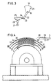
- the contour of the arm 21 is shown in FIG. 3, which essentially has an approximate triangular shape. This shape also contributes to the reinforcement of the one-sided fabric slider plates 16.
- the arms 21 are rotatably mounted on the fixed shaft 8 and are driven individually, as can be seen from FIG. 3.
- a drive lever 22 is attached to each arm 21, and the piston rod 24 of a pneumatic cylinder 25 acts on its free end 23.
- the pneumatic cylinder 25 is supported on the frame 1.
- the compressed air required to drive the pneumatic cylinder 25 is supplied by a pressure wave 26 via a control 27.
- FIG. 4 shows the seven old material slide plates 16 in the folded position, into which they were pivoted by the seven pneumatic cylinders 25. In contrast, only the cloth table 11 is stationary.
- FIG. 4 shows a view similar to that in FIG.
- the slider II now takes back the material web 20 via the slider plate I.
- the slide plate II is stopped and the slide plate III is started.
- the slide plate III can be adjusted in its swivel range by a movable stop (not visible). This means that deviations in size can be taken into account before folding a material web.
- the folded edge 33 of the slide III accordingly does not have to lie exactly above the folded edge 31.
- the slide IV is started, the folding edge 34 of which lies above the folding edge 32 of the slide II.
- the slide V is started, which forms a further folded edge 35 perpendicularly above the folded edge 31 of the slide plate I.
- the slide plate VI is not started, but the slide plate VII is started beforehand, and its edge is stopped vertically above the folded edge 35. Now the slide plate VI is started, which travels between the slide plates VI and VII and takes the material web along until the sensor 17 signals the end edge 19, whereby the movement of the slide plate VII is stopped. Finally, the restrained end part 38 with the end edge 19 is now placed manually over the slide plate VII. This completes the folding process.
- the clamping device 15 is opened and the material web is extended laterally, which is possible with regard to the one-sided mounting of the old material slide plates 16. Then the old material slide plates 16 are brought back into the rest position shown in Figure 1, that is, the odd slide plates are pivoted to the side of the clamping device 15 and the straight slide plates on the opposite side. The machine is now ready for the next folding process.
Landscapes
- Engineering & Computer Science (AREA)
- Textile Engineering (AREA)
- Folding Of Thin Sheet-Like Materials, Special Discharging Devices, And Others (AREA)
- Preliminary Treatment Of Fibers (AREA)
Priority Applications (1)
| Application Number | Priority Date | Filing Date | Title |
|---|---|---|---|
| AT88102842T ATE74329T1 (de) | 1987-09-18 | 1988-02-25 | Maschine und verfahren zum falten von textilen materialbahnen. |
Applications Claiming Priority (2)
| Application Number | Priority Date | Filing Date | Title |
|---|---|---|---|
| CH3606/87 | 1987-09-18 | ||
| CH3606/87A CH674354A5 (cg-RX-API-DMAC7.html) | 1987-09-18 | 1987-09-18 |
Publications (2)
| Publication Number | Publication Date |
|---|---|
| EP0307536A1 EP0307536A1 (de) | 1989-03-22 |
| EP0307536B1 true EP0307536B1 (de) | 1992-04-01 |
Family
ID=4259605
Family Applications (1)
| Application Number | Title | Priority Date | Filing Date |
|---|---|---|---|
| EP88102842A Expired - Lifetime EP0307536B1 (de) | 1987-09-18 | 1988-02-25 | Maschine und Verfahren zum Falten von textilen Materialbahnen |
Country Status (4)
| Country | Link |
|---|---|
| EP (1) | EP0307536B1 (cg-RX-API-DMAC7.html) |
| AT (1) | ATE74329T1 (cg-RX-API-DMAC7.html) |
| CH (1) | CH674354A5 (cg-RX-API-DMAC7.html) |
| DE (1) | DE3869708D1 (cg-RX-API-DMAC7.html) |
Family Cites Families (2)
| Publication number | Priority date | Publication date | Assignee | Title |
|---|---|---|---|---|
| DE1216833B (de) * | 1963-09-21 | 1966-05-18 | Mechanische Buntweberei Brenne | Falt- und Buegelmaschine |
| DE2228808C2 (de) * | 1972-06-13 | 1974-04-18 | Conrad 8741 Saal Arbter | Mehrfachfaltvorrichtung |
-
1987
- 1987-09-18 CH CH3606/87A patent/CH674354A5/de not_active IP Right Cessation
-
1988
- 1988-02-25 EP EP88102842A patent/EP0307536B1/de not_active Expired - Lifetime
- 1988-02-25 DE DE8888102842T patent/DE3869708D1/de not_active Expired - Fee Related
- 1988-02-25 AT AT88102842T patent/ATE74329T1/de not_active IP Right Cessation
Also Published As
| Publication number | Publication date |
|---|---|
| ATE74329T1 (de) | 1992-04-15 |
| DE3869708D1 (de) | 1992-05-07 |
| CH674354A5 (cg-RX-API-DMAC7.html) | 1990-05-31 |
| EP0307536A1 (de) | 1989-03-22 |
Similar Documents
| Publication | Publication Date | Title |
|---|---|---|
| DE3938278C2 (de) | Vorrichtung zum Positionieren von entlang Führungen bewegbaren Schlitten oder dergleichen | |
| DE2544409C3 (de) | Vorrichtung an Nähanlagen zum Bilden eines doppelten Umschlages an den Schnittkanten von flach aufliegenden Materialbahnen | |
| WO1998051499A2 (de) | Verfahren und vorrichtung zur montage biegsamer platten, z.b. druckplatten | |
| DE3512358C2 (cg-RX-API-DMAC7.html) | ||
| DE2709738A1 (de) | Brennschneidmaschine | |
| EP0193750B1 (de) | Vorrichtung zum Ausriffeln von Fäden aus einem Gewebe | |
| DE7525743U (de) | Einrichtung zum herstellen von paspeloeffnungen in zuschnitteilen von bekleidungsstuecken | |
| DE2318011A1 (de) | Automatische vorrichtung zum annaehen von taschen auf kleidungsstuecken | |
| EP0307536B1 (de) | Maschine und Verfahren zum Falten von textilen Materialbahnen | |
| DE2728967C3 (de) | Nähmaschine zum Nähen kantenparalleler Randnähte in aus mehreren Stofflagen bestehenden Werkstücken | |
| EP0425724B1 (de) | Biegemaschine | |
| DE2348623C3 (de) | Anschlußvorrichtung | |
| DE4029891C1 (cg-RX-API-DMAC7.html) | ||
| DE2723432C3 (de) | Tischanschlag für eine Stanzmaschine | |
| DE478475C (de) | Plissiermaschine | |
| DE20118340U1 (de) | Vorrichtung zum maßgenauen Schneiden von bandförmigen Materialien | |
| DE2629117B1 (de) | Naehmaschine mit einer faltvorrichtung | |
| DE4229955C2 (de) | Vorrichtung zum Vereinzeln von gestapelten biegeschlaffen Teilen | |
| DE2605234C3 (de) | Messerkopf für eine Gefrierfleischschneidemaschine | |
| DE10011162C1 (de) | Näheinheit zum Herstellen von Falten und Abnähern | |
| DE69300688T2 (de) | Vorrichtung zum automatischen Positionieren von Strümpfen in einer Strumpfhosennähmaschine. | |
| DE29514185U1 (de) | Einstellvorrichtung für eine Faltschiene an einer Nähmaschine | |
| DE1479355C (de) | Antriebseinrichtung zum schrittweisen Drehen eines zur Verbindung von Arbeitssta tionen angeordneten Drehtisches | |
| DE2423869B2 (de) | Vorrichtung zum querschneiden einer textilbahn | |
| DE2345325A1 (de) | Verfahren und vorrichtung zum steppen einer naht |
Legal Events
| Date | Code | Title | Description |
|---|---|---|---|
| PUAI | Public reference made under article 153(3) epc to a published international application that has entered the european phase |
Free format text: ORIGINAL CODE: 0009012 |
|
| AK | Designated contracting states |
Kind code of ref document: A1 Designated state(s): AT BE DE ES FR GB IT LU NL SE |
|
| 17P | Request for examination filed |
Effective date: 19890828 |
|
| 17Q | First examination report despatched |
Effective date: 19901218 |
|
| GRAA | (expected) grant |
Free format text: ORIGINAL CODE: 0009210 |
|
| AK | Designated contracting states |
Kind code of ref document: B1 Designated state(s): AT BE DE ES FR GB IT LU NL SE |
|
| PG25 | Lapsed in a contracting state [announced via postgrant information from national office to epo] |
Ref country code: IT Free format text: LAPSE BECAUSE OF FAILURE TO SUBMIT A TRANSLATION OF THE DESCRIPTION OR TO PAY THE FEE WITHIN THE PRE;WARNING: LAPSES OF ITALIAN PATENTS WITH EFFECTIVE DATE BEFORE 2007 MAY HAVE OCCURRED AT ANY TIME BEFORE 2007. THE CORRECT EFFECTIVE DATE MAY BE DIFFERENT FROM THE ONE RECORDED.SCRIBED TIME-LIMIT Effective date: 19920401 Ref country code: ES Free format text: THE PATENT HAS BEEN ANNULLED BY A DECISION OF A NATIONAL AUTHORITY Effective date: 19920401 Ref country code: BE Effective date: 19920401 Ref country code: NL Effective date: 19920401 Ref country code: GB Effective date: 19920401 Ref country code: SE Effective date: 19920401 |
|
| REF | Corresponds to: |
Ref document number: 74329 Country of ref document: AT Date of ref document: 19920415 Kind code of ref document: T |
|
| REF | Corresponds to: |
Ref document number: 3869708 Country of ref document: DE Date of ref document: 19920507 |
|
| EN | Fr: translation not filed | ||
| PG25 | Lapsed in a contracting state [announced via postgrant information from national office to epo] |
Ref country code: FR Effective date: 19920821 |
|
| NLV1 | Nl: lapsed or annulled due to failure to fulfill the requirements of art. 29p and 29m of the patents act | ||
| GBV | Gb: ep patent (uk) treated as always having been void in accordance with gb section 77(7)/1977 [no translation filed] | ||
| PLBE | No opposition filed within time limit |
Free format text: ORIGINAL CODE: 0009261 |
|
| STAA | Information on the status of an ep patent application or granted ep patent |
Free format text: STATUS: NO OPPOSITION FILED WITHIN TIME LIMIT |
|
| PG25 | Lapsed in a contracting state [announced via postgrant information from national office to epo] |
Ref country code: AT Effective date: 19930225 |
|
| PG25 | Lapsed in a contracting state [announced via postgrant information from national office to epo] |
Ref country code: LU Free format text: LAPSE BECAUSE OF NON-PAYMENT OF DUE FEES Effective date: 19930228 |
|
| 26N | No opposition filed | ||
| REG | Reference to a national code |
Ref country code: FR Ref legal event code: ST |
|
| PGFP | Annual fee paid to national office [announced via postgrant information from national office to epo] |
Ref country code: DE Payment date: 19940224 Year of fee payment: 7 |
|
| PG25 | Lapsed in a contracting state [announced via postgrant information from national office to epo] |
Ref country code: DE Effective date: 19951101 |