EP0307304A2 - Elément d'étanchéité pour fenêtres lisses - Google Patents
Elément d'étanchéité pour fenêtres lisses Download PDFInfo
- Publication number
- EP0307304A2 EP0307304A2 EP88402243A EP88402243A EP0307304A2 EP 0307304 A2 EP0307304 A2 EP 0307304A2 EP 88402243 A EP88402243 A EP 88402243A EP 88402243 A EP88402243 A EP 88402243A EP 0307304 A2 EP0307304 A2 EP 0307304A2
- Authority
- EP
- European Patent Office
- Prior art keywords
- carrier
- longitudinally
- window
- wall
- generally
- Prior art date
- Legal status (The legal status is an assumption and is not a legal conclusion. Google has not performed a legal analysis and makes no representation as to the accuracy of the status listed.)
- Withdrawn
Links
Images

Classifications
-
- B—PERFORMING OPERATIONS; TRANSPORTING
- B60—VEHICLES IN GENERAL
- B60J—WINDOWS, WINDSCREENS, NON-FIXED ROOFS, DOORS, OR SIMILAR DEVICES FOR VEHICLES; REMOVABLE EXTERNAL PROTECTIVE COVERINGS SPECIALLY ADAPTED FOR VEHICLES
- B60J10/00—Sealing arrangements
- B60J10/20—Sealing arrangements characterised by the shape
- B60J10/23—Sealing arrangements characterised by the shape assembled from two or more parts
- B60J10/235—Sealing arrangements characterised by the shape assembled from two or more parts the parts being joined along their longitudinal direction
-
- B—PERFORMING OPERATIONS; TRANSPORTING
- B60—VEHICLES IN GENERAL
- B60J—WINDOWS, WINDSCREENS, NON-FIXED ROOFS, DOORS, OR SIMILAR DEVICES FOR VEHICLES; REMOVABLE EXTERNAL PROTECTIVE COVERINGS SPECIALLY ADAPTED FOR VEHICLES
- B60J10/00—Sealing arrangements
- B60J10/15—Sealing arrangements characterised by the material
- B60J10/16—Sealing arrangements characterised by the material consisting of two or more plastic materials having different physical or chemical properties
-
- B—PERFORMING OPERATIONS; TRANSPORTING
- B60—VEHICLES IN GENERAL
- B60J—WINDOWS, WINDSCREENS, NON-FIXED ROOFS, DOORS, OR SIMILAR DEVICES FOR VEHICLES; REMOVABLE EXTERNAL PROTECTIVE COVERINGS SPECIALLY ADAPTED FOR VEHICLES
- B60J10/00—Sealing arrangements
- B60J10/15—Sealing arrangements characterised by the material
- B60J10/18—Sealing arrangements characterised by the material provided with reinforcements or inserts
-
- B—PERFORMING OPERATIONS; TRANSPORTING
- B60—VEHICLES IN GENERAL
- B60J—WINDOWS, WINDSCREENS, NON-FIXED ROOFS, DOORS, OR SIMILAR DEVICES FOR VEHICLES; REMOVABLE EXTERNAL PROTECTIVE COVERINGS SPECIALLY ADAPTED FOR VEHICLES
- B60J10/00—Sealing arrangements
- B60J10/70—Sealing arrangements specially adapted for windows or windscreens
- B60J10/74—Sealing arrangements specially adapted for windows or windscreens for sliding window panes, e.g. sash guides
Definitions
- This invention relates to sealing elements for automobiles and more particularly to sealing elements for flush mounted vehicle windows.
- vehicle windows may be designed to be flush or substantially flush with the outer surface of the vehicle body.
- any such outer guide member must be relatively thin so that the window will still be substantially flush with the vehicle body.
- the outer guide member must be easily mounted to the vehicle.
- One object of the present invention is to provide a sealing element for a flush mounted moveable vehicle window which will provide a positive seal against the window by inhibiting outward movement of the window, yet permit a substantially flush window configuration.
- Another object of the present invention is to provide a sealing element for flush mounted windows in which there is no read through so that a smooth, substantially planar and aesthetic appearance is presented.
- a further object of the present invention is to provide a sealing element for flush mounted windows which can be relatively easily shaped by a conventional roll forming apparatus into the shape of a window opening.
- the present invention comprises a first member for making contact and being retained in an opening for receiving a moveable window and a second member cooperating with the first member for defining a window channel.
- the second member forms an outer restraint for the window.
- a common carrier extends between and forms a support for the first member and the second member.
- the common carrier comprises a rigid metal and has an imperforate, substantially planar, shape-sustaining, longitudinally rigid portion in the second member and a longitudinally flexible portion in the first member.
- the longitudinally flexible portion of the carrier may have perforations or corrugations to provide longitudinal flexibility.
- the first and second members form a first generally U-shaped element having an outer leg and an inner leg.
- the invention may also include a second generally U-shaped element wherein the outer leg of the first U-shaped element is substantially planar and forms the outer window restraint, and the carrier extends through the U-shaped elements and is longitudinally rigid in the outer leg and longitudinally flexible otherwise.
- the second U-shaped element may have a common wall with the first U-shaped element.
- the present invention also contemplates a method comprising forming a window seal carrier by modifying an elongated strip of relatively rigid metal so that a first elongated portion of the metal remains relatively rigid and a second elongated portion of the metal is relatively flexible.
- the carrier is transversely bent to form a window guide channel such that the first elongated portion forms an outer guiding and retaining wall for a window received in the channel.
- the carrier is longitudinally bent to take the shape of a window opening.
- the second elongated portion of the metal may be made relatively flexible by forming perforations therein or by forming corrugations therein.
- the method may further comprise applying a coating of soft material over the carrier.
- the coating may be applied by extrusion.
- Fig. 1 shows a typical automobile door 10 having a vertically moveable window 12 mounted in a sealing and guiding structure 14 according to the present invention.
- Structure 14 extends around the top of the window 12 and is bent at corners 12a, 12b and 12c to conform to the shape of the window opening.
- Fig. 2 shows the configuration of the sealing and guiding structure 14.
- This structure has a first U-shaped portion 18 comprising an outer wall 20, a second wall 22 and a web portion 24 extending between walls 20 and 22.
- the structure also has a second U-shaped portion 26 formed of an inner wall 28, wall 22 and a second web portion 30.
- the second U-shaped portion 26 attaches to a body flange 32 of the automobile, as shown in Fig. 3.
- the length of the web portion 24 is sufficient that the outer wall 20 is substantially flush with the outer surface of the vehicle door panel 34.
- a sealing lip 36 is mounted on the U-shaped portion 26 and extends toward the wall 20 so as to form a seal against window 12.
- Flocking 21 may be applied to the inner surface of U-shaped member 18 and the outer surface of the sealing lip 36 as shown in Figs. 2 and 3 to reduce friction and promote sliding of the window 12.
- the sealing and guiding structure 14 is formed with a carrier member 40 over which a layer of rubber or synthetic resin 41 is extruded.
- the carrier member 40 has been solid and inflexible longitudinally. This made it difficult to bend the structure to conform to the shape of the window opening.
- the carrier 40 extends through the entire width of the sealing and guiding structure 14 but is solid only inside of wall 20.
- the carrier is punched as shown at openings 42 elsewhere. In this manner, only the outer wall 40 of the carrier is solid and rigid.
- the remainder of the carrier is relatively flexible so that the sealing and guiding structure 14 can be more easily bent to conform to the window shape using a roll bending apparatus.
- Fig. 4 shows the punched carrier 40 in greater detail.
- the carrier may be made from steel, aluminum or other rigid material.
- the carrier is made from one millimeter thick steel so that it is substantially rigid and resists bending.
- the carrier is punched using known techniques so as to leave a longitudinal portion of the carrier 50 imperforate and substantially planar but so as to form openings 42 in the remainder of the carrier.
- the size and the positioning of the openings 42 are consistent with standard punched carriers as would be apparent to one of ordinary skill in the art.
- the openings ultimately form strips of material 44 which are parallel and interconnected by webs 46.
- the portion 50 along one lateral edge of the carrier remains solid.
- the rigid, substantially planar portion 50 forms a support for the outer wall 20, whereas the punched portion of the carrier forms the support for walls 22 and 28 as well as connecting webs 24 and 30.
- the punched portion of the carrier can be made as flexible as desired.
- the perforations can be approximately an eighth of an inch thick leaving metal strips 44 which are about 3/16 inch thick.
- the web portions 46 then have a length equal to about the thickness of the openings 42 and can have a width approximately the same size.
- sealing lips may be formed wherever desired, such as on the outer wall 20, during this extrusion process. Additional sealing lips such as sealing lip 36 can either be formed of the same rubber coating 41 or can be formed in a co-extrusion process using a softer material.
- the final coated product is longitudinally bent into the shape of the window opening.
- the solid portion 50 of the carrier gives the final product a rigidity which is useful for automated assembly of the sealing and guiding strip 14 in the door. That is, it is preferable to have the sealing and guiding strip 14 rigid in its final shape so that it can be fit directly into the door opening.
- the outer wall 20 is relatively rigid along its length to insure proper guiding of the window.
- the outer surface of portion 50 of the carrier is substantially planar so that when the rubber coating 52 is extruded onto it, the outer surface of the rubber coating on wall 20 is also smooth and planar and presents an aesthetic, finished appearance which complements the finished appearance of the outside of the vehicle.
- the length of the wall 20 depends on the application. However, in practice, it has been found that a length of approximately 1/2 inch is adequate with the solid portion of the carrier being approximately 3/8 inch. This provides the desired degree of rigidity and enables the outer surface of the sealing and guiding element 14 to be smooth and wrinkle-free.
- any process which can produce a flexible portion of a carrier will suffice in place of a punching process. That is, while web portions 46 are shown in Figs. 4 and 5 with adjacent web portions being offset from one another to provide flexibility, a portion of the carrier may be corrugated to provide flexibility. Any other process which will enable the same portion of the carrier to be flexible would also suffice.
- the primary concern is that the final product need be roll formed in only one plane so as to reduce the difficulty of this step in the manufacturing process.
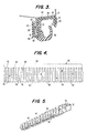
- FIG. 6 shows a sealing and guiding structure 70 having a first U-shaped portion 72, a second U-shaped portion 74 and a third U-shaped portion 76.
- the U-shaped portion 76 attaches to a vehicle flange 32.
- an outer wall 90 retains the window within the first U-shaped portion 72.
- a first central wall 92 forms the inner wall of the first U-shaped portion 72 and the outer wall of the second U-shaped portion 74.
- a second inner wall 94 completes the second U-shaped portion 74 and forms the outer wall of the third U-shaped portion 76.
- a sealing lip 96 is clamped between walls 92 and 94 and has its own carrier 98.
- a carrier 80 extends throughout the sealing and guiding element 70 and is formed from a single piece of metal.
- the carrier is bent back on itself at bend 82 to form the support structure for wall 92. Accordingly, in this area, there is a double thickness of carrier.
- this carrier has four parallel walls which must be bent in order to longitudinally bend the sealing and guiding element to conform to the window shape. Accordingly, this carrier is particularly rigid in the longitudinal direction. By punching all of the carrier except for the portion 100 in the outer wall 90, the carrier can be made more flexible and can easily be roll formed.
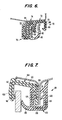
- Fig. 7 shows a third sealing and guiding element 101 which is composed of two separate members.
- a first member 104 is generally U-shaped and has an outer wall 106 and an inner wall 108 connected by a web portion 110.
- a first carrier 112 forms the support for member 104.
- Carrier 112 includes a solid portion 114 imbedded in the outer wall 104. The remainder of carrier 112 is punched so as to enable this portion of the carrier to be easily roll formed to conform to the shape of the window.
- a second member 120 is also U-shaped and has a first leg 122 and a second leg 124 interconnected by a web portion 126.
- a flocked sealing lip 130 extends toward wall 106.
- This member has its own carrier 132. This carrier can be completely punched if desired so as to enable member 120 to be flexed into the desired shape when it is applied to the vehicle.
- the member 104 is first applied to the vehicle flange 32 and is glued or riveted in place. Member 120 is then applied over the flange 32 and inner wall 108 to help hold member 104 to the vehicle body.
- each of the sealing and guiding elements forms a decorative trim piece on the interior of the vehicle.
- wall 122 of sealing and guiding element 101 is exposed to the interior of the vehicle and is intended to be aesthetic. Because a punched carrier is used in this wall, ordinarily, there would be read through of the punched carrier which would compromise the aesthetics of the element. However, it is conventional to flock the outer surface of this member. Flocking provides a rougher surface which hides read through. However, if it is desired to have a smooth surface on the interior, member 120 of sealing and guiding element 101 can also be made with a partially solid and partially punched carrier. That is, the portion of the carrier 132 within inner wall 122 could be made solid to eliminate read through.
- both element 104 and element 120 could be easily manufactured and roll formed into the desired shape and then mounted in place. There would be no read through on either the interior or the exterior of the sealing and guiding element so that aesthetic appeal would be maintained on both the inside and the outside of the vehicle without the need for any flocking applied to exterior surfaces.
Applications Claiming Priority (2)
| Application Number | Priority Date | Filing Date | Title |
|---|---|---|---|
| US9442787A | 1987-09-09 | 1987-09-09 | |
| US94427 | 1987-09-09 |
Publications (2)
| Publication Number | Publication Date |
|---|---|
| EP0307304A2 true EP0307304A2 (fr) | 1989-03-15 |
| EP0307304A3 EP0307304A3 (fr) | 1990-03-21 |
Family
ID=22245129
Family Applications (1)
| Application Number | Title | Priority Date | Filing Date |
|---|---|---|---|
| EP88402243A Withdrawn EP0307304A3 (fr) | 1987-09-09 | 1988-09-07 | Elément d'étanchéité pour fenêtres lisses |
Country Status (2)
| Country | Link |
|---|---|
| EP (1) | EP0307304A3 (fr) |
| JP (1) | JPH023525A (fr) |
Cited By (6)
| Publication number | Priority date | Publication date | Assignee | Title |
|---|---|---|---|---|
| FR2648887A1 (fr) * | 1989-06-21 | 1990-12-28 | Draftex Ind Ltd | Bande d'etancheite a renforcement metallique |
| EP0412782A2 (fr) * | 1989-08-07 | 1991-02-13 | The Standard Products Company | Coulisse de glace avec bande décorative intégrée |
| EP0748711A1 (fr) * | 1995-06-12 | 1996-12-18 | Draftex Industries Limited | Renforcement pour bandes d'étanchéité, de garnissage et de finition et procédés pour fabriquer de tels renforcements |
| FR2775224A1 (fr) * | 1998-02-26 | 1999-08-27 | Btr Sealing Systems France | Nouveau profile d'etancheite pour encadrement de vitre coulissante, notamment de porte de vehicule automobile, et son procede de fabrication |
| FR2794692A1 (fr) * | 1999-06-14 | 2000-12-15 | Btr Sealing Systems France | Nouvelle armature rigide pour profile en elastomere ou plastomere et profile equipe de cette armature |
| WO2008006409A1 (fr) * | 2006-07-12 | 2008-01-17 | Meteor Gummiwerke K.H. Bädje GmbH & Co. KG | Agencement de joint |
Citations (6)
| Publication number | Priority date | Publication date | Assignee | Title |
|---|---|---|---|---|
| GB640966A (en) * | 1948-02-03 | 1950-08-02 | Beckett Laycock & Watkinson | Improvements in or relating to windows |
| US3108338A (en) * | 1961-01-06 | 1963-10-29 | Republic Ind Corp | Weather sealing strips and mounting means therefor |
| FR2297366A1 (fr) * | 1975-01-09 | 1976-08-06 | Draftex Dev Ag | Bande d'etancheite souple formee de deux elements associes longitudinalement |
| GB2140065A (en) * | 1983-05-19 | 1984-11-21 | Mesnel Sa Ets | A sealing strip for a retractible window |
| DE8204475U1 (de) * | 1982-02-18 | 1985-11-28 | Schlegel Gmbh, 2000 Hamburg | Dichtstreifen aus polymerem Werkstoff mit einer metallischen Einlage |
| EP0241264A2 (fr) * | 1986-04-07 | 1987-10-14 | Bridgestone Australia Ltd., | Profilé de guidage pour vitres coulissantes |
-
1988
- 1988-09-07 EP EP88402243A patent/EP0307304A3/fr not_active Withdrawn
- 1988-09-09 JP JP63226306A patent/JPH023525A/ja active Pending
Patent Citations (6)
| Publication number | Priority date | Publication date | Assignee | Title |
|---|---|---|---|---|
| GB640966A (en) * | 1948-02-03 | 1950-08-02 | Beckett Laycock & Watkinson | Improvements in or relating to windows |
| US3108338A (en) * | 1961-01-06 | 1963-10-29 | Republic Ind Corp | Weather sealing strips and mounting means therefor |
| FR2297366A1 (fr) * | 1975-01-09 | 1976-08-06 | Draftex Dev Ag | Bande d'etancheite souple formee de deux elements associes longitudinalement |
| DE8204475U1 (de) * | 1982-02-18 | 1985-11-28 | Schlegel Gmbh, 2000 Hamburg | Dichtstreifen aus polymerem Werkstoff mit einer metallischen Einlage |
| GB2140065A (en) * | 1983-05-19 | 1984-11-21 | Mesnel Sa Ets | A sealing strip for a retractible window |
| EP0241264A2 (fr) * | 1986-04-07 | 1987-10-14 | Bridgestone Australia Ltd., | Profilé de guidage pour vitres coulissantes |
Cited By (11)
| Publication number | Priority date | Publication date | Assignee | Title |
|---|---|---|---|---|
| FR2648887A1 (fr) * | 1989-06-21 | 1990-12-28 | Draftex Ind Ltd | Bande d'etancheite a renforcement metallique |
| EP0412782A2 (fr) * | 1989-08-07 | 1991-02-13 | The Standard Products Company | Coulisse de glace avec bande décorative intégrée |
| EP0412782A3 (en) * | 1989-08-07 | 1991-04-17 | The Standard Products Company | Integral trim and glass run channel |
| US5095656A (en) * | 1989-08-07 | 1992-03-17 | The Standard Products Company | Integral trim and glass run channel |
| AU646636B2 (en) * | 1989-08-07 | 1994-03-03 | Standard Products Company, The | Integral trim and glass run channel |
| EP0748711A1 (fr) * | 1995-06-12 | 1996-12-18 | Draftex Industries Limited | Renforcement pour bandes d'étanchéité, de garnissage et de finition et procédés pour fabriquer de tels renforcements |
| FR2775224A1 (fr) * | 1998-02-26 | 1999-08-27 | Btr Sealing Systems France | Nouveau profile d'etancheite pour encadrement de vitre coulissante, notamment de porte de vehicule automobile, et son procede de fabrication |
| EP0938995A1 (fr) | 1998-02-26 | 1999-09-01 | Btr Sealing Systems France | Nouveau profilé d'étanchéité pour encadrement de vitre coulissante, notamment de porte de véhicule automobile, et son procédé de fabrication |
| FR2794692A1 (fr) * | 1999-06-14 | 2000-12-15 | Btr Sealing Systems France | Nouvelle armature rigide pour profile en elastomere ou plastomere et profile equipe de cette armature |
| EP1060929A1 (fr) * | 1999-06-14 | 2000-12-20 | Btr Sealing Systems France | Nouvelle armature rigide pour profilé en élastomère ou plastomère et profilé équipé de cette armature. |
| WO2008006409A1 (fr) * | 2006-07-12 | 2008-01-17 | Meteor Gummiwerke K.H. Bädje GmbH & Co. KG | Agencement de joint |
Also Published As
| Publication number | Publication date |
|---|---|
| EP0307304A3 (fr) | 1990-03-21 |
| JPH023525A (ja) | 1990-01-09 |
Similar Documents
| Publication | Publication Date | Title |
|---|---|---|
| US5493814A (en) | Weatherstrip assembly including a glass run channel and belt weatherstrip with decorative cover | |
| US4949507A (en) | One-piece expandable weatherstrip | |
| US5194312A (en) | Profiled sealing strip with two reinforcing bands | |
| US4800681A (en) | Sealing and guiding element for flush mounted movable automobile window | |
| EP1232887B1 (fr) | Structure de cadre de porte pour véhicule automobile | |
| EP0437974B1 (fr) | Bande d'étanchéité intégrée avec une section lissée à une courbure d'angle | |
| US5095656A (en) | Integral trim and glass run channel | |
| EP0532163B1 (fr) | Bande d'étanchéité de largeur extensible | |
| EP0327141A2 (fr) | Structure pour les fenêtres dans une véhicule automobile | |
| US5475947A (en) | Flexible sealing unit for movable windows | |
| JPH078636B2 (ja) | シールストリツプ | |
| JPS59223517A (ja) | 窓ガラスを窓開口に取り付けるための装置 | |
| EP0307304A2 (fr) | Elément d'étanchéité pour fenêtres lisses | |
| KR970005782B1 (ko) | 차량부착 모울딩 | |
| JP2001341591A (ja) | ドアシール構造 | |
| JPH05139217A (ja) | 自動車用ウエザストリツプ | |
| EP0246008A1 (fr) | Bande d'étanchéité | |
| JP3040334B2 (ja) | 芯材入りウエザーストリップ | |
| GB2429027A (en) | Window sealing and guiding arrangements | |
| JP3178325B2 (ja) | ドアガラスウエザストリップの取付構造 | |
| GB2421268A (en) | Sealing, trimming and finishing strips and vehicle doors incorporating such strips | |
| JP2677109B2 (ja) | 自動車用ウエザストリップ | |
| JP3104259B2 (ja) | 自動車用ウェザーストリップ | |
| JPH1148879A (ja) | 自動車用オープニングトリム | |
| JPH0542889Y2 (fr) |
Legal Events
| Date | Code | Title | Description |
|---|---|---|---|
| PUAI | Public reference made under article 153(3) epc to a published international application that has entered the european phase |
Free format text: ORIGINAL CODE: 0009012 |
|
| AK | Designated contracting states |
Kind code of ref document: A2 Designated state(s): DE FR GB |
|
| PUAL | Search report despatched |
Free format text: ORIGINAL CODE: 0009013 |
|
| AK | Designated contracting states |
Kind code of ref document: A3 Designated state(s): DE FR GB |
|
| RAP1 | Party data changed (applicant data changed or rights of an application transferred) |
Owner name: SHELLER-GLOBE CORPORATION |
|
| 17P | Request for examination filed |
Effective date: 19900706 |
|
| 17Q | First examination report despatched |
Effective date: 19910604 |
|
| STAA | Information on the status of an ep patent application or granted ep patent |
Free format text: STATUS: THE APPLICATION IS DEEMED TO BE WITHDRAWN |
|
| 18D | Application deemed to be withdrawn |
Effective date: 19911015 |