EP0306928B1 - Magnet für einen Motor und Herstellungsverfahren - Google Patents
Magnet für einen Motor und Herstellungsverfahren Download PDFInfo
- Publication number
- EP0306928B1 EP0306928B1 EP88114628A EP88114628A EP0306928B1 EP 0306928 B1 EP0306928 B1 EP 0306928B1 EP 88114628 A EP88114628 A EP 88114628A EP 88114628 A EP88114628 A EP 88114628A EP 0306928 B1 EP0306928 B1 EP 0306928B1
- Authority
- EP
- European Patent Office
- Prior art keywords
- magnet
- less
- magnets
- ihc
- motor
- Prior art date
- Legal status (The legal status is an assumption and is not a legal conclusion. Google has not performed a legal analysis and makes no representation as to the accuracy of the status listed.)
- Expired - Lifetime
Links
Images
Classifications
-
- H—ELECTRICITY
- H01—ELECTRIC ELEMENTS
- H01F—MAGNETS; INDUCTANCES; TRANSFORMERS; SELECTION OF MATERIALS FOR THEIR MAGNETIC PROPERTIES
- H01F1/00—Magnets or magnetic bodies characterised by the magnetic materials therefor; Selection of materials for their magnetic properties
- H01F1/01—Magnets or magnetic bodies characterised by the magnetic materials therefor; Selection of materials for their magnetic properties of inorganic materials
- H01F1/03—Magnets or magnetic bodies characterised by the magnetic materials therefor; Selection of materials for their magnetic properties of inorganic materials characterised by their coercivity
- H01F1/032—Magnets or magnetic bodies characterised by the magnetic materials therefor; Selection of materials for their magnetic properties of inorganic materials characterised by their coercivity of hard-magnetic materials
- H01F1/04—Magnets or magnetic bodies characterised by the magnetic materials therefor; Selection of materials for their magnetic properties of inorganic materials characterised by their coercivity of hard-magnetic materials metals or alloys
- H01F1/047—Alloys characterised by their composition
- H01F1/053—Alloys characterised by their composition containing rare earth metals
- H01F1/055—Alloys characterised by their composition containing rare earth metals and magnetic transition metals, e.g. SmCo5
- H01F1/057—Alloys characterised by their composition containing rare earth metals and magnetic transition metals, e.g. SmCo5 and IIIa elements, e.g. Nd2Fe14B
- H01F1/0571—Alloys characterised by their composition containing rare earth metals and magnetic transition metals, e.g. SmCo5 and IIIa elements, e.g. Nd2Fe14B in the form of particles, e.g. rapid quenched powders or ribbon flakes
- H01F1/0575—Alloys characterised by their composition containing rare earth metals and magnetic transition metals, e.g. SmCo5 and IIIa elements, e.g. Nd2Fe14B in the form of particles, e.g. rapid quenched powders or ribbon flakes pressed, sintered or bonded together
- H01F1/0576—Alloys characterised by their composition containing rare earth metals and magnetic transition metals, e.g. SmCo5 and IIIa elements, e.g. Nd2Fe14B in the form of particles, e.g. rapid quenched powders or ribbon flakes pressed, sintered or bonded together pressed, e.g. hot working
-
- B—PERFORMING OPERATIONS; TRANSPORTING
- B22—CASTING; POWDER METALLURGY
- B22F—WORKING METALLIC POWDER; MANUFACTURE OF ARTICLES FROM METALLIC POWDER; MAKING METALLIC POWDER; APPARATUS OR DEVICES SPECIALLY ADAPTED FOR METALLIC POWDER
- B22F3/00—Manufacture of workpieces or articles from metallic powder characterised by the manner of compacting or sintering; Apparatus specially adapted therefor ; Presses and furnaces
- B22F3/12—Both compacting and sintering
- B22F3/14—Both compacting and sintering simultaneously
-
- H—ELECTRICITY
- H01—ELECTRIC ELEMENTS
- H01F—MAGNETS; INDUCTANCES; TRANSFORMERS; SELECTION OF MATERIALS FOR THEIR MAGNETIC PROPERTIES
- H01F1/00—Magnets or magnetic bodies characterised by the magnetic materials therefor; Selection of materials for their magnetic properties
- H01F1/01—Magnets or magnetic bodies characterised by the magnetic materials therefor; Selection of materials for their magnetic properties of inorganic materials
- H01F1/03—Magnets or magnetic bodies characterised by the magnetic materials therefor; Selection of materials for their magnetic properties of inorganic materials characterised by their coercivity
- H01F1/032—Magnets or magnetic bodies characterised by the magnetic materials therefor; Selection of materials for their magnetic properties of inorganic materials characterised by their coercivity of hard-magnetic materials
- H01F1/04—Magnets or magnetic bodies characterised by the magnetic materials therefor; Selection of materials for their magnetic properties of inorganic materials characterised by their coercivity of hard-magnetic materials metals or alloys
- H01F1/047—Alloys characterised by their composition
- H01F1/053—Alloys characterised by their composition containing rare earth metals
- H01F1/055—Alloys characterised by their composition containing rare earth metals and magnetic transition metals, e.g. SmCo5
- H01F1/057—Alloys characterised by their composition containing rare earth metals and magnetic transition metals, e.g. SmCo5 and IIIa elements, e.g. Nd2Fe14B
-
- H—ELECTRICITY
- H02—GENERATION; CONVERSION OR DISTRIBUTION OF ELECTRIC POWER
- H02K—DYNAMO-ELECTRIC MACHINES
- H02K1/00—Details of the magnetic circuit
- H02K1/02—Details of the magnetic circuit characterised by the magnetic material
-
- H—ELECTRICITY
- H02—GENERATION; CONVERSION OR DISTRIBUTION OF ELECTRIC POWER
- H02K—DYNAMO-ELECTRIC MACHINES
- H02K15/00—Processes or apparatus specially adapted for manufacturing, assembling, maintaining or repairing of dynamo-electric machines
- H02K15/02—Processes or apparatus specially adapted for manufacturing, assembling, maintaining or repairing of dynamo-electric machines of stator or rotor bodies
- H02K15/03—Processes or apparatus specially adapted for manufacturing, assembling, maintaining or repairing of dynamo-electric machines of stator or rotor bodies having permanent magnets
Definitions
- the present invention relates to a magnet suitable for use in a voice coil motor used in the external memory of an electronic computer or for a motor used in household electrical appliances or factory automation (FA) devices, and, more particularly, to a magnet having a complicated shape which is very difficult for known techniques to provide.
- FA factory automation
- VCM voice coil motors
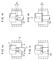
- Figs. 2 and 3 Since the electromagnetic force is proportional to Bg. le, where Bg is the magnetic flux density of a gap and le is the effective length of a coil, larger and flatter plate-shaped magnets or longer ring-shaped magnets having a larger diameter have been sought after so that better magnetic characteristics and a large le can be provided.
- a rare-earth element (R) - Fe - B type permanent magnet having both larger residual flux density (hereinafter referred to as Br) and larger inherent coercive force (hereinafter referred to as iHc) in the VCM in place of a conventionally employed SmCo magnet.
- the Japanese Patent Laid-Open No. 61-266056 discloses a magnet for use in the VCM which has a magnetic flux density Bg in a magnetic circuit increased in order to improve an electromagnetic force (k F ), to increase the control gain (related to 1/k F ) for a transfer function, and to decrease the positioning errors.
- Japanese Patent Laid-Open No. 61-210862 discloses a magnet for use in the VCM which has a magnetic flux density of not less than 0.9 T at a operating point and an excellent rectangularity ratio in the demagnetizing curve.
- Disk rotor type brushless motors employed in household electrical appliances such as VTR and cassette decks incorporate a disk-shaped rotor made of a permanent magnet such as that shown in Fig. 4.
- a decreased moment of inertia reduces the ability to cope with disturbances and increases in wow and flutter (unevenness in rotation). Therefore, flat and large disk-shaped magnets have been sought in order to improve the "flywheel effect" (GD2), where D is the diameter of the rotor and G is the gravitational constant.
- the present inventor proposes a concept of "surface magnification" to standardize the shape of magnet for use in a motor. More specifically, the surface magnification is defined by (the volume of a magnet)/(the thickness in the direction of easy magnetization)3, and it can be said that permanent magnets having a large surface magnification have been demanded when improving performance of office automation (OA) devices.
- OA office automation
- permanent magnets are manufactured by the transverse magnetic field compacting method, in which the direction of application of a magnetic field is perpendicular to the direction of compacting. They are also manufactured by the longitudinal magnetic field compacting method in which the direction of application of the magnetic field is parallel to the direction of compacting. It is known from experience that rare earth type magnets made of the same materials have different magnetic characteristics when the different methods are adapted to manufacture the magnets, and that the former method produces a permanent magnet having a higher Br.
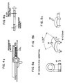
- the magnet shown in Fig. 5(a) has a ring-like shape in which the direction of easy magnetization (M) coincides with the direction of thickness.
- the magnet shown in Fig. 5(b) has a C-shape in which L is long compared with the width.
- Fig. 5(c) shows a magnet having a fan-like shape in which L is long.
- magnets for use in VCM and magnets for use in disk-rotor type brushless motors must be manufactured by the longitudinal magnetic field compacting method.
- the direction of application of the magnetic field coincides with the direction of compression in this method, the orientation of grains are disturbed in the direction of thickness, decreasing Br during the compacting. Therefore, it has been impossible to manufacture anisotropic sintered magnets appropriate for the use which have the above-described shapes.
- warm working magnets have been proposed in order to eliminate the above-described problems of the sintering (see European Patent Laid-Open Publication No. 0133758).
- magnetically anisotropic magnets are manufactured by plastically warm deforming the alloy powder produced by the rapid quenching method.
- the direction of compression becomes substantially identical with the direction of easy magnetization during plastic deformation, disturbance of orientation of grains only occurs at a very low level, unlike the sintered magnets, and this makes warm working suitable to the manufacture of plate-like magnets.
- an object of the present invention is to provide a flat Nd - Fe - B type magnet produced by warm working which has a Br in the direction of thickness higher than that of sintered magnets and a surface magnification of 6 or more.
- the present invention provides, in one of its aspect, a magnetically anisotropic magnet for use in a motor, comprising at least one rare earth element (R), Fe and boron (B), said magnet having fine crystal grains, said magnet further comprising Ga so that the magnet has a surface magnification of not less than 6, a residual magnetic flux density in the direction of easy magnetization of not less than 1.1 T and a coercive force of not less than 960 kA/m.
- R rare earth element
- B boron
- Ga is added to the composition of the magnet for the motor so that the resultant magnet has a residual magnetic flux density in the direction of easy magnetization of not less than 11 kG and a coercive force of not less than 12 kOe.
- the composition of the magnet is represented by RaFe ba1 Co b B c Ga d M e in terms of atomic percent in which the R is at least one element selected from a group consisting of Nd, Pr, Dy, Tb and Ce which satisfies (Nd + Pr)/R ⁇ 0.7 , M being at least element selected from a group consisting of Zn, Al, Si, Nb, Ta, Ti, Zr, Hf and W, 12 ⁇ a ⁇ 18, 0 ⁇ b ⁇ 30, 4 ⁇ c ⁇ 10, 0 ⁇ d ⁇ 3, and 0 ⁇ e ⁇ 2.
- the average crystal grain size thereof is between 0.01 and 0.5 ⁇ m.
- the magnet is made to have anisotropy by the plastic deformation process so that the magnet has improved Br in the direction of thickness, and reduction in iHc apt to occur by heating and plastic deformation processes is suppressed by the addition of Ga, thereby enabling provision of a large magnet having excellent magnetic characteristics and a surface magnification of not less than 6.
- Br is set to 1.1 T or more, because this characteristic has been sought after in recent years and because it is difficult to provide it by the sintering which is effected by use of a press under a longitudinal magnetic field.
- the magnet for the VCM is often used in an air-conditioned computer room, a heat resistance of 80°C or more is in general required because of rise in temperature in the interior of the devices. Therefore, a value of the iHc of 960 kA/m or more is preferable.
- Magnets for use in disk rotor type brushless motors are used under severer conditions than those of the voice coil motors, and a heat-resistance of 100°C or above is in general required.
- iHc is preferably set to 1200 kA/m or more.
- the composition of the R - Fe - B type magnet according to the present invention is substantially the same as that of the conventional magnet except for Ga.
- the R - Fe - B type magnet essentially has R2Fe14B phase or R2(Fe, Co)14B phase.
- the composition of the magnet is determined in the above-described range for the following reasons: if R is set to less than 12 at %, ⁇ -Fe appears, preventing provision of a sufficient proper iHc. If R exceeds 18 at %, Br is reduced. If Nd or Pr which has a high saturation magnetization value is selected as R, (Pr + Nd)/R ⁇ 0.7 should be satisfied in order to attain the Br of 1.1 T or more.
- Ce is contained in an inexpensive material such as didymium etc.
- the magnetic characteristics of a resultant magnet are not adversely affected if the amount of Ce added is small (Ce/R ⁇ 0.1) .
- Dy and Tb are effective to improve iHc.
- the amount thereof should be limited to a value which satisfies (Tb + Dy)/R ⁇ 0.3 in order to obtain the Br of 1.1 T or more.
- the amount of B added is less than 4 at %, the R2Fe14B phase is not sufficiently formed, and Br and iHc are not increased.
- the amount of B is determined between 4 at % and 11 at %.
- Ga is effective to improve iHc. However, if the amount of Ga is less than 0.001 at %, no improvement of iHc is recognized. In order to obtain iHc of 1200 kA/m or more, the amount of Ga should be 0.01 at % or more. However, when the amount of Ga exceeds 2 at %, Br starts to decrease. iHc decreases down to a value lower than that of a magnet which contains no Ga, if the amount of Ga exceeds 3 at %. In consequence, it is preferable for the amount of Ga to be set between 0.001 at % and 3 at %. More preferably, it is set between 0.01 at % and 2 at %.
- M is effective to improve iHc and suppress the growth of crystal grains.
- Zn, Al and Si are capable of improving iHc. If the amount of these elements added is 2 at % or less, degree of decrease in Br is small.
- Nb, Ta, Ti, Zr, Hf and W are effective to suppress the growth of crystal grains. The amount of these elements should be 2 at % or less so as to prevent deterioration of workability.
- the grains of the magnet according to the present invention have a substantially disk-like shape which is prepared by deforming flatly a shape of tetragonal system. Therefore, the average grain size of the magnet according to the present invention is expressed by the diameter of a sphere calculated by a method comprising the steps of : measuring the sizes of thirty or more crystals in the direction of the C axis which is identical with the direction of the easy magnetization by use of the intercept method (defined in JIS G-0551) to thereby calculate an average size of the crystals in the direction of the C axis ; measuring the thicknesses of those crystals to thereby calculate an average thickness of the crystals ; and calculating a diameter of the sphere having the same volume as those crystals' average volume calculated from both the average size and thickness.
- the average grain diameter is set to 0.5 ⁇ m or less, since a diameter of more than 0.5 ⁇ m decreases the iHc.
- the present invention provides, in another of its aspects, a method of manufacturing a magnet for a motor, which comprising the steps of: forming flakes by rapid quenching a molten alloy consisting of at least one rare earth element (R), Fe, boron (B) and an optional metal element (M); compacting the flakes to provide a green compact; and warm plastic working the green compact at a temperature between 600°C and 800°C at a strain rate of 0.0001 to 0.1 per second with a plastic working ratio (ho/h) of not less than 2 so that a resultant magnet is magnetically anisotropic and has a surface magnification of not less than 6, a residual magnetic flux density in the direction of easy magnetization of not less than 1.1 T, and a coercive force of not less than 960 kA/m.
- a method of manufacturing a magnet for a motor comprising the steps of: forming flakes by rapid quenching a molten alloy consisting of at least one rare earth element (R), Fe,
- a magnet having a surface magnification of 6 or more by the transverse magnetic field press.
- a magnet having a rectangular shape or any of the above-described shapes can be readily worked since it is made magnetically anisotropic by the plastic deformation process.
- a plastic working ratio is expressed by ho/h, where ho is the height of a sample which is not plastically worked and h is the height of a plastically worked sample.
- the plastic working ratio is set to 2 or more so as to obtain the Br of 1.1 T or more.
- compacting is conducted so as to increase the density of a magnet.
- Usual hot press or hot hydrostatic extrusion may be employed.
- Upsetting, extrusion, forging or spinning may be employed to perform plastic deformation in the present invention.
- warm upsetting is most preferable, since it is capable of applying magnetic anisotropy to a magnet most effectively. If dies shaped into a final form are employed, near net shape working is possible.
- the deformation temperature is set between 600°C and 800°C, because a temperature less than 600°C greatly increases deformation resistance and produces a magnet having a low Br. With the temperature of more than 800°C, iHc becomes less than 960 kA/m due to the growth of crystal grains.
- the strain rate is set to 0.0001 per sec. or more because, if the working time is long, iHc is reduced, which is undesirable from the viewpoint of production efficiency. Also, the strain rate is set to 0.01 per sec. or less because, if it is higher than this maximum value, it is impossible to sufficiently make a magnet anisotropic and because cracks are apt to be caused.
- EP-A-258 609 considered only with respect to novelty
- EP-A-248 981 also considered only with respect to novelty
- EP-A-216 254 and in Patent Abstracts of Japan, Vol. 11, No. 117 (E-498) (2564), dated April 11, 1987.
- EP-A-216 254 teaches the features found in the first part of claim 1, but fails to disclose either the surface magnification feature or a magnet which is anisotropic, and does not teach a residual magnification in the direct of easy magnification of at least 11 kG.
- EP-A-133 758 discloses a method of producing a magnet of the R-Fe-B type by hot working, as in the first part of method claim 2.
- this reference fails to disclose either Ga or the surface magnification feature discussed above, as well as the steps of compacting alloy flakes into a green compact and then warm plastic working the green compact at a strain rate of 0.0001 to 0.1 per second with a plastic working ratio (ho/h) of not less than 2.
- An alloy having the composition of Nd14-Fe 79.25 B6Ga 0.75 in terms of atomic % was prepared by the arc melting, and the prepared alloy was then formed into flakes in an Ar atmosphere by the single roll method.
- the peripheral speed of the roll was 30 m/sec, and the obtained flakes had various shapes having a thickness of 25 ⁇ 3 ⁇ m. It was found by the X-ray analysis that the thus-obtained flakes were a mixture of amorphous and crystal. Subsequently, these flakes were roughly ground to 32 mesh or less, and the ground flakes were shaped into a compact having a diameter of 60 mm and a height of 21 mm by use of dies under the pressure of 3.0 kbar.
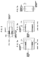
- the compact was set in working space defined by an upper punch 1, a lower punch 4 and dies 3 made of a heat-resistant alloy, as shown in Fig. 1(a).
- a high-frequency coil 2 was provided around the dies 3.
- the upper punch 1 employed in this example was of the flat type, while the lower punch 4 had a protrusion 5 at its upper portion.
- the body set in the working space was compacted until it had a height (ho) of 16 mm while the surface of the dies was being heated up to about 620°C by the high-frequency coil, as shown in Fig. 1(b).
- the density of 5.8 g/cm3 of the green compact 51 prior to compacting was increased to 7.5 g/cm3 after the compacting (52). At this time, the body did not yet show magnetic anisotropy.
- Fig. 1(c) shows the state of a sample 53 which is being warm upset
- Fig. 1(d) shows a sample 54 which has been warm upset.
- the height (h) of the sample which had been warm upset was 7 mm. Therefore, the plastic working ratio ho/h was 2.3.
- the rate at which the temperature was raised was 80°C/min, the compacting time was 0.4 minute, and the strain rate of the plastic working was 0.025 sec ⁇ 1.
- the obtained magnet had a size of 60 in diameter and 7 mm in height.
- the volume thereof was 10,996 mm3, and the thickness thereof in the direction of easy magnetization was 7 mm. Therefore, the surface magnification obtained by dividing the volume of the magnet by the cube of the thickness was 32.
- the end surfaces of the obtained magnet had substantially no cracks.
- the average grain diameter was 0.4 ⁇ m, the Br in the direction of thickness was 1.22 T, and iHc was 1570 kA/m.
- a sintered magnet having a composition Nd13Dy2Fe77B6, was prepared for comparison by use of the longitudinal magnetic field press method.
- the transverse magnetic field press method in which the direction of compression was perpendicular to the direction of application of the magnetic field was also tried.
- the orientation of grains was extremely non-uniform, and it was impossible to obtain a sintered magnet.
- the Br was 1.16 T, and the iHc was 1370 kA/m.
- the gap magnetic flux density of the voice coil motor employing the magnet according to the present invention was 0.69 T, while that of the voice coil motor employing the comparison example was 0,6 T, which means that an improvement of about 15% was achieved in the invention.
- Magnets containing Ga in various amounts ranging between 0 at % and 5 at % were manufactured in the same manner as in the case of Example 1.
- Table 1 shows the magnetic characteristics of those magnets and the gap magnetic flux densities Bg of the voice coil motors employing these magnets.
- Table 1 Amount of Ga (at %) Br (T) iHc (kA/m) Bg (T) 0 1.31 936 0.600 0.001 1.26 1024 0.628 0.01 1.24 1296 0.685 0.1 1.20 1592 0.692 1 1.18 1632 0.695 2 1.16 1648 0.697 3 1.11 1672 0.698 5 0.98 912 0.699
- Permanent magnets having the composition of Nd14Fe bal B6Ga 0.2 M e (where M is one element selected from the group of Zn, Al, Si, Nb, Ta, Ti, Zr, Hf and W, and e is equal to 2 or 3) in terms of atomic % were manufactured in the same manner as in the case of Example 1.
- Table 2 shows the characteristics of these magnets. It is obvious that addition of up to 2 atomic % of Zn, Al or Si improves the iHc and increases the Br to 1.1 T or more.
- Magnets were manufactured under the same conditions as those of Example 1 with the exception that various amount of Co were added.
- Table 3 shows the magnetic characteristics of the thus-obtained magnets.
- ⁇ denotes the mean temperature coefficient of Br obtained when the temperature varied between 25 and 140°C.
- Magnets were manufactured under the same conditions as those in Example 1 except for strain rate.
- Table 4 shows the magnetic characteristics obtained at various strain rates. As can be seen from the table, it is preferable for the strain rate to be set between 0.0001 and 0.1 per second.
- Magnets were manufactured under the same conditions as those in Example 1 except for deformation temperature.
- Table 6 shows the magnetic characteristics obtained when deformation temperature was varied. From the Table 6, it is clear that the deformation temperature is preferably selected in a range of 600 to 800°C.
- Table 6 Temperature (°C) iHc (kA/m) Br (T) Cracks 550 1864 0.97 Many 600 1784 1.10 Few 700 1608 1.21 No crack 800 1296 1.23 No crack 850 864 1.07 No crack
- Permanent magnets having various surface magnifications were manufactured in the same manner as in the case of Example 1 by use of compacts having various heights.
- Tables 7 and 8 show the magnetic characteristics of the magnets manufactured in this Example and the sintered magnets, respectively. It was impossible to obtain sintered magnets having a surface magnification of 6 or more.
- Magnets were manufactured under the same conditions as those of Example 1 except for thickness. At the same time, disk-like shaped magnets which were comparison examples (sintered magnets having the same components) were manufactured. Both the magnets had dimensions of an outer diameter of 60 mm, an inner diameter of 8 mm and a thickness of 3 mm (the direction of easy magnetization being the direction of the thickness). The thus-obtained magnets were assembled to provide disk rotor type brushless motors by using a shaft and thirty two magnetic poles. When the output characteristics of the motors were examined, the output characteristic of the motor employing the magnets according to the present invention were 21% higher than that of the comparison example. No irregular rotation nor wow flatter occurred, and good torque ripple rate were obtained.
- the magnet for the motor according to the present invention can be formed into a complicated shape and can have a residual magnetic flux density of 1.1 T or more and a coercive force of 960 kA/m or more. In consequence, the performance of a resultant motor can be improved, and the size thereof can be decreased.
Landscapes
- Engineering & Computer Science (AREA)
- Power Engineering (AREA)
- Manufacturing & Machinery (AREA)
- Chemical & Material Sciences (AREA)
- Crystallography & Structural Chemistry (AREA)
- Inorganic Chemistry (AREA)
- Mechanical Engineering (AREA)
- Hard Magnetic Materials (AREA)
- Permanent Field Magnets Of Synchronous Machinery (AREA)
- Reciprocating, Oscillating Or Vibrating Motors (AREA)
Claims (4)
- Magnet zur Verwendung in einem Motor, der mindestens ein Seltenerd-Element (R), Fe, B und Ga enthält und feinkristalline Körner einer mittleren Größe nicht über 0,5 µm, eine magnetische Remanenz-Flußdichte von nicht weniger als 1,1 T und eine Koerzitivkraft von nicht weniger als 960 kA/m hat, wobei
der Magnet magnetisch anisotrop ist,
die magnetische Remanenz-Flußdichte von nicht weniger als 1,1 T in der Richtung leichter Magnetisierung vorliegt und
der Magnet eine Oberflächenvergrößerung, definiert als (Magnetvolumen) dividiert durch (Dicke in Richtung der leichten Magnetisierung)³, von nicht weniger als 6 aufweist. - Magnet nach Anspruch 1 mit einer Zusammensetzung
RaFeRestCobBcGadMe
in Atomprozent, wobei R mindestens eines der Elemente Nd, Pr, Dy, Tb und Ce mit
- Verfahren zur Herstellung eines Magneten nach Anspruch 1 oder 2, gekennzeichnet durch die folgenden Schritte:
Herstellen von Flocken durch rasches Abschrecken,
Verdichten der Flocken unter Bildung eines grünen verdichteten Produktes und
plastisches Warmverformen des grünen verdichteten Erzeugnisses bei einer Temperatur zwischen 600 und 800 °C, einer Dehnungsrate von 0,0001 bis 0,1 s⁻¹, und einem Verhältnis der plastischen Verformung (ho/h) von nicht weniger als 2. - Verfahren nach Anspruch 3, wobei die plastische Warmverformung in einem Warmpressen besteht.
Applications Claiming Priority (2)
| Application Number | Priority Date | Filing Date | Title |
|---|---|---|---|
| JP62225892A JPH01257308A (ja) | 1987-09-09 | 1987-09-09 | ボイスコイルモーター用磁石 |
| JP225892/87 | 1987-09-09 |
Publications (3)
| Publication Number | Publication Date |
|---|---|
| EP0306928A2 EP0306928A2 (de) | 1989-03-15 |
| EP0306928A3 EP0306928A3 (en) | 1989-10-11 |
| EP0306928B1 true EP0306928B1 (de) | 1993-12-01 |
Family
ID=16836511
Family Applications (1)
| Application Number | Title | Priority Date | Filing Date |
|---|---|---|---|
| EP88114628A Expired - Lifetime EP0306928B1 (de) | 1987-09-09 | 1988-09-07 | Magnet für einen Motor und Herstellungsverfahren |
Country Status (5)
| Country | Link |
|---|---|
| US (1) | US4960474A (de) |
| EP (1) | EP0306928B1 (de) |
| JP (1) | JPH01257308A (de) |
| CA (1) | CA1310821C (de) |
| DE (1) | DE3885980T2 (de) |
Families Citing this family (15)
| Publication number | Priority date | Publication date | Assignee | Title |
|---|---|---|---|---|
| JP2553278B2 (ja) * | 1987-10-08 | 1996-11-13 | 川崎製鉄株式会社 | 希土類−遷移金属系磁石合金 |
| JP3037699B2 (ja) * | 1988-09-30 | 2000-04-24 | 日立金属株式会社 | 耐割れ性及び配向性を改善した温間加工磁石ならびにその製造方法 |
| US5098486A (en) * | 1989-05-23 | 1992-03-24 | Hitachi Metals, Ltd. | Magnetically anisotropic hotworked magnet and method of producing same |
| US5143560A (en) * | 1990-04-20 | 1992-09-01 | Hitachi Metals, Inc., Ltd. | Method for forming Fe-B-R-T alloy powder by hydrogen decrepitation of die-upset billets |
| US5178691A (en) * | 1990-05-29 | 1993-01-12 | Matsushita Electric Industrial Co., Ltd. | Process for producing a rare earth element-iron anisotropic magnet |
| US5395462A (en) * | 1991-01-28 | 1995-03-07 | Mitsubishi Materials Corporation | Anisotropic rare earth-Fe-B system and rare earth-Fe-Co-B system magnet |
| US6004407A (en) * | 1995-09-22 | 1999-12-21 | Alps Electric Co., Ltd. | Hard magnetic materials and method of producing the same |
| US6332932B1 (en) * | 1999-04-20 | 2001-12-25 | Sumitomo Special Metals Co., Ltd. | Punch, powder pressing apparatus and powder pressing method |
| US6633457B1 (en) * | 2000-07-25 | 2003-10-14 | Data Storage Institute | Actuator assembly with orthogonal force generation |
| EP1180772B1 (de) * | 2000-08-11 | 2011-01-12 | Nissan Motor Company Limited | Anisotroper Magnet und zugehöriges Herstellungsverfahren |
| JP2004515193A (ja) * | 2000-11-27 | 2004-05-20 | フランク・ジェイ・フェセラ | 永久磁石モータ |
| US7675202B1 (en) | 2007-07-18 | 2010-03-09 | Benjamin Huang | Isotropic ring magnet linear voice coil motor |
| JP2013098485A (ja) * | 2011-11-04 | 2013-05-20 | Toyota Motor Corp | 希土類磁石の製造装置と製造方法 |
| JP2013098486A (ja) * | 2011-11-04 | 2013-05-20 | Toyota Motor Corp | 希土類磁石の製造方法 |
| JP6668289B2 (ja) * | 2017-05-12 | 2020-03-18 | ミネベアミツミ株式会社 | R−t−b系永久磁石の製造方法およびr−t−b系永久磁石 |
Citations (3)
| Publication number | Priority date | Publication date | Assignee | Title |
|---|---|---|---|---|
| EP0133758A2 (de) * | 1983-08-04 | 1985-03-06 | General Motors Corporation | Permanente Magnete aus Eisen, Metallen aus seltenen Erden und Bor durch Wärmebehandlung |
| EP0216254A1 (de) * | 1985-09-10 | 1987-04-01 | Kabushiki Kaisha Toshiba | Dauermagnet |
| EP0248981A2 (de) * | 1986-06-12 | 1987-12-16 | Kabushiki Kaisha Toshiba | Dauermagnet und Dauermagnetlegierung |
Family Cites Families (3)
| Publication number | Priority date | Publication date | Assignee | Title |
|---|---|---|---|---|
| US4374665A (en) * | 1981-10-23 | 1983-02-22 | The United States Of America As Represented By The Secretary Of The Navy | Magnetostrictive devices |
| US4827235A (en) * | 1986-07-18 | 1989-05-02 | Kabushiki Kaisha Toshiba | Magnetic field generator useful for a magnetic resonance imaging instrument |
| EP0258609B1 (de) * | 1986-07-23 | 1993-02-03 | Hitachi Metals, Ltd. | Dauermagnet mit guter thermischer Stabilität |
-
1987
- 1987-09-09 JP JP62225892A patent/JPH01257308A/ja active Pending
-
1988
- 1988-09-07 DE DE88114628T patent/DE3885980T2/de not_active Expired - Fee Related
- 1988-09-07 EP EP88114628A patent/EP0306928B1/de not_active Expired - Lifetime
- 1988-09-08 CA CA000576754A patent/CA1310821C/en not_active Expired - Lifetime
- 1988-09-08 US US07/241,735 patent/US4960474A/en not_active Expired - Fee Related
Patent Citations (3)
| Publication number | Priority date | Publication date | Assignee | Title |
|---|---|---|---|---|
| EP0133758A2 (de) * | 1983-08-04 | 1985-03-06 | General Motors Corporation | Permanente Magnete aus Eisen, Metallen aus seltenen Erden und Bor durch Wärmebehandlung |
| EP0216254A1 (de) * | 1985-09-10 | 1987-04-01 | Kabushiki Kaisha Toshiba | Dauermagnet |
| EP0248981A2 (de) * | 1986-06-12 | 1987-12-16 | Kabushiki Kaisha Toshiba | Dauermagnet und Dauermagnetlegierung |
Non-Patent Citations (1)
| Title |
|---|
| Patent Abstracts of Japan, vol. 11, No. 117, (E-498)(2564), April 11, 1987 * |
Also Published As
| Publication number | Publication date |
|---|---|
| JPH01257308A (ja) | 1989-10-13 |
| CA1310821C (en) | 1992-12-01 |
| EP0306928A3 (en) | 1989-10-11 |
| DE3885980T2 (de) | 1994-03-24 |
| US4960474A (en) | 1990-10-02 |
| DE3885980D1 (de) | 1994-01-13 |
| EP0306928A2 (de) | 1989-03-15 |
Similar Documents
| Publication | Publication Date | Title |
|---|---|---|
| US4601875A (en) | Process for producing magnetic materials | |
| EP0306928B1 (de) | Magnet für einen Motor und Herstellungsverfahren | |
| US4814139A (en) | Permanent magnet having good thermal stability and method for manufacturing same | |
| US4921553A (en) | Magnetically anisotropic bond magnet, magnetic powder for the magnet and manufacturing method of the powder | |
| US4975130A (en) | Permanent magnet materials | |
| US4859255A (en) | Permanent magnets | |
| EP0134305A1 (de) | Permanentmagnet | |
| EP4439594A1 (de) | Neodym-eisen-bor-magnet sowie herstellungsverfahren dafür und verwendung davon | |
| US5009706A (en) | Rare-earth antisotropic powders and magnets and their manufacturing processes | |
| JP3084748B2 (ja) | 希土類永久磁石の製造方法 | |
| JP3092672B2 (ja) | 希土類−Fe−Co−B系異方性磁石 | |
| JPH01219143A (ja) | 焼結永久磁石材料とその製造方法 | |
| US5536334A (en) | Permanent magnet and a manufacturing method thereof | |
| EP0477810A2 (de) | Permanent magnetisierbares Puder vom R-Fe-B Typ und Verbundmagnet daraus | |
| JPH02308512A (ja) | 偏倚異方性を有するR―Fe―B系永久磁石及びその製造方法 | |
| JP2576672B2 (ja) | 磁気的異方性および耐食性に優れた希土類ーFeーCoーB系永久磁石粉末およびボンド磁石 | |
| JPH045740B2 (de) | ||
| JP3196224B2 (ja) | 希土類−Fe−Co−B系異方性磁石 | |
| KR900006533B1 (ko) | 이방성 자성분말과 이의 자석 및 이의 제조방법 | |
| JP2586199B2 (ja) | 磁気的異方性および耐食性に優れた希土類―Fe―Co―B系永久磁石粉末およびボンド磁石 | |
| JPH045738B2 (de) | ||
| JPH044385B2 (de) | ||
| JPS6077961A (ja) | 永久磁石材料の製造方法 | |
| KR930002559B1 (ko) | 영구자석 및 그 제조방법 | |
| JPH04314315A (ja) | ボンド磁石の製造方法 |
Legal Events
| Date | Code | Title | Description |
|---|---|---|---|
| PUAI | Public reference made under article 153(3) epc to a published international application that has entered the european phase |
Free format text: ORIGINAL CODE: 0009012 |
|
| AK | Designated contracting states |
Kind code of ref document: A2 Designated state(s): DE FR GB |
|
| RAP1 | Party data changed (applicant data changed or rights of an application transferred) |
Owner name: HITACHI METALS, LTD. |
|
| PUAL | Search report despatched |
Free format text: ORIGINAL CODE: 0009013 |
|
| AK | Designated contracting states |
Kind code of ref document: A3 Designated state(s): DE FR GB |
|
| 17P | Request for examination filed |
Effective date: 19891221 |
|
| 17Q | First examination report despatched |
Effective date: 19920317 |
|
| GRAA | (expected) grant |
Free format text: ORIGINAL CODE: 0009210 |
|
| AK | Designated contracting states |
Kind code of ref document: B1 Designated state(s): DE FR GB |
|
| REF | Corresponds to: |
Ref document number: 3885980 Country of ref document: DE Date of ref document: 19940113 |
|
| ET | Fr: translation filed | ||
| PG25 | Lapsed in a contracting state [announced via postgrant information from national office to epo] |
Ref country code: GB Effective date: 19940907 |
|
| PLBE | No opposition filed within time limit |
Free format text: ORIGINAL CODE: 0009261 |
|
| STAA | Information on the status of an ep patent application or granted ep patent |
Free format text: STATUS: NO OPPOSITION FILED WITHIN TIME LIMIT |
|
| 26N | No opposition filed | ||
| GBPC | Gb: european patent ceased through non-payment of renewal fee |
Effective date: 19940907 |
|
| PGFP | Annual fee paid to national office [announced via postgrant information from national office to epo] |
Ref country code: FR Payment date: 19950911 Year of fee payment: 8 |
|
| PGFP | Annual fee paid to national office [announced via postgrant information from national office to epo] |
Ref country code: DE Payment date: 19950918 Year of fee payment: 8 |
|
| PG25 | Lapsed in a contracting state [announced via postgrant information from national office to epo] |
Ref country code: FR Effective date: 19960930 |
|
| PG25 | Lapsed in a contracting state [announced via postgrant information from national office to epo] |
Ref country code: DE Effective date: 19970603 |
|
| REG | Reference to a national code |
Ref country code: FR Ref legal event code: ST |
|
| REG | Reference to a national code |
Ref country code: FR Ref legal event code: ST |