EP0306754A2 - Dispositif pour le montage d'un branchement d'une seule âme d'un câble multiconducteur - Google Patents
Dispositif pour le montage d'un branchement d'une seule âme d'un câble multiconducteur Download PDFInfo
- Publication number
- EP0306754A2 EP0306754A2 EP88113552A EP88113552A EP0306754A2 EP 0306754 A2 EP0306754 A2 EP 0306754A2 EP 88113552 A EP88113552 A EP 88113552A EP 88113552 A EP88113552 A EP 88113552A EP 0306754 A2 EP0306754 A2 EP 0306754A2
- Authority
- EP
- European Patent Office
- Prior art keywords
- clamping
- clamping element
- projection
- bore
- conductor
- Prior art date
- Legal status (The legal status is an assumption and is not a legal conclusion. Google has not performed a legal analysis and makes no representation as to the accuracy of the status listed.)
- Granted
Links
Images

Classifications
-
- H—ELECTRICITY
- H01—ELECTRIC ELEMENTS
- H01R—ELECTRICALLY-CONDUCTIVE CONNECTIONS; STRUCTURAL ASSOCIATIONS OF A PLURALITY OF MUTUALLY-INSULATED ELECTRICAL CONNECTING ELEMENTS; COUPLING DEVICES; CURRENT COLLECTORS
- H01R4/00—Electrically-conductive connections between two or more conductive members in direct contact, i.e. touching one another; Means for effecting or maintaining such contact; Electrically-conductive connections having two or more spaced connecting locations for conductors and using contact members penetrating insulation
- H01R4/24—Connections using contact members penetrating or cutting insulation or cable strands
- H01R4/2404—Connections using contact members penetrating or cutting insulation or cable strands the contact members having teeth, prongs, pins or needles penetrating the insulation
- H01R4/2408—Connections using contact members penetrating or cutting insulation or cable strands the contact members having teeth, prongs, pins or needles penetrating the insulation actuated by clamping screws
-
- H—ELECTRICITY
- H01—ELECTRIC ELEMENTS
- H01R—ELECTRICALLY-CONDUCTIVE CONNECTIONS; STRUCTURAL ASSOCIATIONS OF A PLURALITY OF MUTUALLY-INSULATED ELECTRICAL CONNECTING ELEMENTS; COUPLING DEVICES; CURRENT COLLECTORS
- H01R4/00—Electrically-conductive connections between two or more conductive members in direct contact, i.e. touching one another; Means for effecting or maintaining such contact; Electrically-conductive connections having two or more spaced connecting locations for conductors and using contact members penetrating insulation
- H01R4/28—Clamped connections, spring connections
- H01R4/38—Clamped connections, spring connections utilising a clamping member acted on by screw or nut
- H01R4/44—Clamping areas on both sides of screw
Definitions
- the present invention relates to a device for producing a branch from a single insulated wire of a multi-conductor cable, wherein a first and a second clamping element can be brought into clamping contact with one another by means of a screw arrangement.
- branch terminal which consists of detachably connectable segments, spacers being provided between the individual segments.
- the present invention has for its object to provide a device for branching a single insulated wire of a multi-conductor cable, which can be assembled in a very simple manner with a minimum number of individual parts without much time.
- the features according to the invention result in a simple clamping contact of the main wire by means of a screw with simple assembly.
- the distance between the tilting support and the recesses for the main wire ensures high clamping forces.
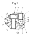
- a device shown in FIGS. 1 and 2 for branching a single insulated wire of a multi-conductor cable has a first 1 and a second 2 clamping element. These two clamping elements can be pressed against one another by means of a screw arrangement 3, so that a clamping contact arises between the individual elements 1 and 2.
- the first clamping element 1 has a projection 5 through which a bore 4 runs. This hole is intended to accommodate a branch conductor.
- a recess 7 is provided in the first clamping element 1. This recess is designed to span the main vein.
- the second clamping element 2 each has a recess 15 and 9, the part-circular recess 15 forming the support part 8 for the clamping element 1.
- the radius of the recess 15 corresponds approximately to the radius of the projection 5, so that when the clamping contact is produced, the projection 5 is spanned by the recess 15 along a wide area of its circumference.
- the projection 5 can be rotated about the drilling axis 6 in the recess 15, the recess 15 forming a tilting support 16. In the case of a clamp contact to be produced, this arrangement also guarantees the necessary anti-rotation protection.
- the clamping elements are provided with an insulating surface coating.
- the recessed clamping screws 3a make the proposed clamp very space-saving.
- the assembly is also correspondingly simple:
- a prepared branch conductor is guided through the bore 4 and clamped by means of a screw 13.
- the clamping element with its recesses 7 and 9 is then pushed onto the main wire.
- the screw 3a is tightened so that the clamping elements 1 and 2 are brought into clamping contact.
- the annular cutting edges 11 penetrate into the insulating material of the main wire and displace it into the cavities 12. As soon as the annular cutting edges 11 have penetrated the insulating material, the clamping contact is produced.
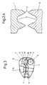
- the projection 5 of the clamping element 1 is nose-shaped.
- the support part 8 of the clamping element 2 has a flat support surface 10, whereby the rounded nose creates a linear support of the clamping element 1 on the clamping part 2, about which the clamping element 2 can be pivoted about the tilting support 16 when tightened by means of the screw arrangement 3.
- the clamping element 1 has an eye 14 for the screw 13 for clamping the branch conductor in the bore 4.
- a contact surface 10 is arranged on each side of the eye 14.
- the arrangement of the projections 5 on both sides of the eye 14 prevents the two clamping elements 1, 2 from rotating relative to one another when the screw 3a is tightened.
- the recesses 9 and 7 with the annular cutting edges 11 correspond to the embodiment variant shown in FIGS. 1 and 2, wherein the cavities 12 between the annular cutting edges 11 can also be semicircular in cross section in order to reduce notch stresses, as shown in FIG. 2a.
Landscapes
- Suspension Of Electric Lines Or Cables (AREA)
- Testing Of Short-Circuits, Discontinuities, Leakage, Or Incorrect Line Connections (AREA)
- Connections By Means Of Piercing Elements, Nuts, Or Screws (AREA)
- Multi-Conductor Connections (AREA)
- Cable Accessories (AREA)
- Communication Cables (AREA)
Priority Applications (1)
| Application Number | Priority Date | Filing Date | Title |
|---|---|---|---|
| AT88113552T ATE83338T1 (de) | 1987-09-07 | 1988-08-20 | Einrichtung zur herstellung einer abzweigung von einer einzelnen ader eines mehrleiterkabels. |
Applications Claiming Priority (2)
| Application Number | Priority Date | Filing Date | Title |
|---|---|---|---|
| CH3440/87 | 1987-09-07 | ||
| CH3440/87A CH673910A5 (fr) | 1987-09-07 | 1987-09-07 |
Publications (3)
| Publication Number | Publication Date |
|---|---|
| EP0306754A2 true EP0306754A2 (fr) | 1989-03-15 |
| EP0306754A3 EP0306754A3 (en) | 1990-06-13 |
| EP0306754B1 EP0306754B1 (fr) | 1992-12-09 |
Family
ID=4256002
Family Applications (1)
| Application Number | Title | Priority Date | Filing Date |
|---|---|---|---|
| EP88113552A Expired - Lifetime EP0306754B1 (fr) | 1987-09-07 | 1988-08-20 | Dispositif pour le montage d'un branchement d'une seule âme d'un câble multiconducteur |
Country Status (5)
| Country | Link |
|---|---|
| EP (1) | EP0306754B1 (fr) |
| AT (1) | ATE83338T1 (fr) |
| CH (1) | CH673910A5 (fr) |
| DE (1) | DE3876548D1 (fr) |
| DK (1) | DK167787B1 (fr) |
Cited By (1)
| Publication number | Priority date | Publication date | Assignee | Title |
|---|---|---|---|---|
| CN102646954A (zh) * | 2012-05-17 | 2012-08-22 | 天津玖辰机械设备制造有限公司 | 一种用于低压电力电缆的机械式分支连接器 |
Family Cites Families (4)
| Publication number | Priority date | Publication date | Assignee | Title |
|---|---|---|---|---|
| DE1117685C2 (de) * | 1958-09-08 | 1962-06-07 | Alois Schiffmann Dipl Kfm | Zweibacken-Starkstromklemme |
| DE1198435B (de) * | 1961-04-17 | 1965-08-12 | Alois Schiffmann Dipl Kfm | Verbindungs- und Abzweigklemme fuer isolierte Leitungen |
| FR2294556A1 (fr) * | 1974-12-12 | 1976-07-09 | Verlant Et Beaurain | Connecteur de derivation, notamment pour lignes sous tension |
| DE2903960C3 (de) * | 1979-02-02 | 1984-01-19 | Karl Pfisterer Elektrotechnische Spezialartikel Gmbh & Co Kg, 7000 Stuttgart | Vollisolierte Abzweigklemme |
-
1987
- 1987-09-07 CH CH3440/87A patent/CH673910A5/de not_active IP Right Cessation
-
1988
- 1988-08-20 EP EP88113552A patent/EP0306754B1/fr not_active Expired - Lifetime
- 1988-08-20 DE DE8888113552T patent/DE3876548D1/de not_active Expired - Fee Related
- 1988-08-20 AT AT88113552T patent/ATE83338T1/de not_active IP Right Cessation
- 1988-09-06 DK DK495088A patent/DK167787B1/da not_active Application Discontinuation
Cited By (1)
| Publication number | Priority date | Publication date | Assignee | Title |
|---|---|---|---|---|
| CN102646954A (zh) * | 2012-05-17 | 2012-08-22 | 天津玖辰机械设备制造有限公司 | 一种用于低压电力电缆的机械式分支连接器 |
Also Published As
| Publication number | Publication date |
|---|---|
| DK167787B1 (da) | 1993-12-13 |
| DK495088D0 (da) | 1988-09-06 |
| DK495088A (da) | 1989-03-08 |
| CH673910A5 (fr) | 1990-04-12 |
| ATE83338T1 (de) | 1992-12-15 |
| EP0306754A3 (en) | 1990-06-13 |
| DE3876548D1 (de) | 1993-01-21 |
| EP0306754B1 (fr) | 1992-12-09 |
Similar Documents
| Publication | Publication Date | Title |
|---|---|---|
| DE69712414T2 (de) | Verfahren und Anordung zum schnellen Anschliessen zweier elektrischen Käbel | |
| EP1423890B1 (fr) | Raccord de câbles | |
| DE2735838C2 (de) | Elektrische Anschlußklemme und elektrisches Kabelverbindungsglied | |
| EP0218133A2 (fr) | Borne électrique sans vis | |
| EP0083738B1 (fr) | Elément de connexion pour câbles électriques pourvu de bornes tranchantes | |
| DE2305403C3 (de) | Lötfreie Anschlußstelle | |
| CH687113A5 (de) | Leiteranschlussvorrichtung fuer Schwachstromanlagen. | |
| EP0306754B1 (fr) | Dispositif pour le montage d'un branchement d'une seule âme d'un câble multiconducteur | |
| DE2653357A1 (de) | Klemmelement zum abisolierfreien anschluss elektrischer leiter | |
| DE19604615C1 (de) | Kontaktierungseinrichtung | |
| DE69804524T2 (de) | Isolations-Perforierverbinder | |
| DE10216491C1 (de) | Steckverbinder mit Schneidklemmkontakten | |
| DE29709127U1 (de) | Elektrische Steckvorrichtung | |
| DE10210789A1 (de) | Anschlussklemme zum Verbinden eines elektrischen Leiters an einer einzelnen Stromschiene | |
| DE3601788C2 (fr) | ||
| EP0993689B1 (fr) | Dispositif de connexion pour conducteurs electriques isoles non denudes | |
| DE2932966C2 (fr) | ||
| DE2352430C3 (de) | Elektrische Anschluß- oder/und Verbindungsklemme für insbesondere rohrförmige Leiter | |
| AT527571B1 (de) | Erdungsklemme | |
| DE3127284A1 (de) | Batterieklemme | |
| DE3621483C2 (fr) | ||
| DE3436256C2 (fr) | ||
| DE2528487A1 (de) | Schraubenlose klemmverbindung | |
| DE10309004A1 (de) | Anschlußvorrichtung mit Steckverbindung | |
| AT394647B (de) | Vollisolierte abzweigklemme fuer isolierte freileitungsleiter |
Legal Events
| Date | Code | Title | Description |
|---|---|---|---|
| PUAI | Public reference made under article 153(3) epc to a published international application that has entered the european phase |
Free format text: ORIGINAL CODE: 0009012 |
|
| 17P | Request for examination filed |
Effective date: 19880820 |
|
| AK | Designated contracting states |
Kind code of ref document: A2 Designated state(s): AT CH DE LI NL SE |
|
| PUAL | Search report despatched |
Free format text: ORIGINAL CODE: 0009013 |
|
| AK | Designated contracting states |
Kind code of ref document: A3 Designated state(s): AT CH DE LI NL SE |
|
| 17Q | First examination report despatched |
Effective date: 19920413 |
|
| GRAA | (expected) grant |
Free format text: ORIGINAL CODE: 0009210 |
|
| AK | Designated contracting states |
Kind code of ref document: B1 Designated state(s): AT CH DE LI NL SE |
|
| REF | Corresponds to: |
Ref document number: 83338 Country of ref document: AT Date of ref document: 19921215 Kind code of ref document: T |
|
| REF | Corresponds to: |
Ref document number: 3876548 Country of ref document: DE Date of ref document: 19930121 |
|
| PLBE | No opposition filed within time limit |
Free format text: ORIGINAL CODE: 0009261 |
|
| STAA | Information on the status of an ep patent application or granted ep patent |
Free format text: STATUS: NO OPPOSITION FILED WITHIN TIME LIMIT |
|
| 26N | No opposition filed | ||
| PGFP | Annual fee paid to national office [announced via postgrant information from national office to epo] |
Ref country code: DE Payment date: 19940713 Year of fee payment: 7 |
|
| PGFP | Annual fee paid to national office [announced via postgrant information from national office to epo] |
Ref country code: AT Payment date: 19940719 Year of fee payment: 7 |
|
| PGFP | Annual fee paid to national office [announced via postgrant information from national office to epo] |
Ref country code: SE Payment date: 19940831 Year of fee payment: 7 Ref country code: NL Payment date: 19940831 Year of fee payment: 7 |
|
| PGFP | Annual fee paid to national office [announced via postgrant information from national office to epo] |
Ref country code: CH Payment date: 19941107 Year of fee payment: 7 |
|
| EAL | Se: european patent in force in sweden |
Ref document number: 88113552.9 |
|
| PG25 | Lapsed in a contracting state [announced via postgrant information from national office to epo] |
Ref country code: AT Effective date: 19950820 |
|
| PG25 | Lapsed in a contracting state [announced via postgrant information from national office to epo] |
Ref country code: SE Effective date: 19950821 |
|
| PG25 | Lapsed in a contracting state [announced via postgrant information from national office to epo] |
Ref country code: LI Effective date: 19950831 Ref country code: CH Effective date: 19950831 |
|
| PG25 | Lapsed in a contracting state [announced via postgrant information from national office to epo] |
Ref country code: NL Effective date: 19960301 |
|
| REG | Reference to a national code |
Ref country code: CH Ref legal event code: PL |
|
| NLV4 | Nl: lapsed or anulled due to non-payment of the annual fee |
Effective date: 19960301 |
|
| PG25 | Lapsed in a contracting state [announced via postgrant information from national office to epo] |
Ref country code: DE Effective date: 19960501 |
|
| EUG | Se: european patent has lapsed |
Ref document number: 88113552.9 |