EP0306623B1 - Electric steam iron - Google Patents
Electric steam iron Download PDFInfo
- Publication number
- EP0306623B1 EP0306623B1 EP88108964A EP88108964A EP0306623B1 EP 0306623 B1 EP0306623 B1 EP 0306623B1 EP 88108964 A EP88108964 A EP 88108964A EP 88108964 A EP88108964 A EP 88108964A EP 0306623 B1 EP0306623 B1 EP 0306623B1
- Authority
- EP
- European Patent Office
- Prior art keywords
- steam iron
- receiving space
- water
- opening
- water tank
- Prior art date
- Legal status (The legal status is an assumption and is not a legal conclusion. Google has not performed a legal analysis and makes no representation as to the accuracy of the status listed.)
- Expired - Lifetime
Links
Images
Classifications
-
- D—TEXTILES; PAPER
- D06—TREATMENT OF TEXTILES OR THE LIKE; LAUNDERING; FLEXIBLE MATERIALS NOT OTHERWISE PROVIDED FOR
- D06F—LAUNDERING, DRYING, IRONING, PRESSING OR FOLDING TEXTILE ARTICLES
- D06F75/00—Hand irons
- D06F75/08—Hand irons internally heated by electricity
- D06F75/10—Hand irons internally heated by electricity with means for supplying steam to the article being ironed
- D06F75/14—Hand irons internally heated by electricity with means for supplying steam to the article being ironed the steam being produced from water in a reservoir carried by the iron
-
- C—CHEMISTRY; METALLURGY
- C02—TREATMENT OF WATER, WASTE WATER, SEWAGE, OR SLUDGE
- C02F—TREATMENT OF WATER, WASTE WATER, SEWAGE, OR SLUDGE
- C02F1/00—Treatment of water, waste water, or sewage
- C02F1/42—Treatment of water, waste water, or sewage by ion-exchange
Definitions
- the invention relates to an electrically operated steam iron with a handle housing, the lower opening is closed by a sole plate provided with outlet openings and with a water tank, a receiving space for a decalcifying agent, which connects to the outlet of the water tank and one under Interposition of a control device connectable evaporator chamber and with a controllable heating device.
- Such electrically operated steam irons require the use of water, which must be evaporated, when used as intended.
- Tap water is often used by the user. From a chemical point of view, such tap water is not pure. Rather, in addition to dissolved gases, it contains a number of salts, or the like, from soils, rocks. are detached.
- the salts contained in tap water include calcium bicarbonate, calcium sulfate and magnesium carbonate. In summary, this is called “hardness" of the water.
- degree of hardness is used to indicate the hardness of the water. The higher the value of a degree of hardness, the harder the water.
- the hardness of the water filled into the water tank plays an important role, because when the tap water is heated, the water is separated into individual components. Some of the separated components, in particular the carbonates, are deposited on the water-carrying parts of the steam iron as a "scale". Scale is undesirable for several reasons. It acts as a heat insulator, which translates into increased energy consumption. In addition, however, pipes or small-diameter lines can become completely clogged with scale over time.
- the scale can be removed by acids. If it is copper, brass or the like. Metals can be used to remove scale from dilute solutions of lactic acid or acetic acid.
- the manufacturers or distributors of electrically operated steam irons therefore generally recommend descaling within certain time intervals. The time intervals in which such descaling must be carried out depend on the degree of hardness of the tap water used.
- So-called descaling display devices are also known, which often operate on an electrical or electronic basis. They have not been able to assert themselves in practice, not least because they require considerable technical effort on the one hand and, on the other hand, because they do do not bring the desired, optimal result.
- a steam iron has become known in which a decalcifying agent is arranged in the area of the inlet of the water tank, the decalcifying agent for recognizing its nature from the outside through a viewing window is visible.
- the decalcifying agent is in a container which is accommodated in a recess in the handle of the steam iron. This recess is closed to the outside of the handle by a removable wall part, which in turn has the viewing window.
- the disadvantage here is that the descaling agent is arranged in the area of the inlet of the water tank. This makes it difficult to fill the water tank because the descaling agent takes a long time to flow through the water.
- the viewing window is part of a section of the handle of the steam iron.
- the container containing the decalcifying agent has no transparent area.
- DE 3 o33 964 A1 shows an electrically heated steam iron, in the water tank of which a softener (a decalcifying agent) is arranged, the softener being separated from the interior of the water tank by a sieve-like, water-permeable wall. It is also intended to accommodate the softener in a cartridge with a sieve-like wall.
- a cartridge is arranged with its water-permeable wall - penetrating the water tank wall - inside the water tank.
- the water-impermeable cartridge bottom is detachably connected to the outer jacket of the water tank.
- the cartridge is screwed into the container wall of the water container and a seal is provided between the cartridge and the water container.
- the softener mass is added loosely to the water tank.
- the container inlet and outlet are closed by sieves. On the one hand, these are intended to prevent the softener from entering the evaporation chamber and, on the other hand, they are to ensure that the contents of the water tank can be emptied if necessary without the softener being lost.
- a closable opening is provided in the container wall to remove the used softener.
- An arrangement of the decalcifying agent in the area of the outlet of a water container is known from DE-A 3014493 for a household appliance with a hot water heater, in particular a coffee machine.
- a multi-part device which is to be used for ironing textiles.
- This device includes a box-shaped housing, the upper side of which is to be used for setting up a steam iron.
- a water container is arranged on the top of the housing in such a way that it can be pivoted into two end positions is. In the effective one end position, water can be taken from the water tank, which is not possible in the other end position. In the effective end position of the water tank, the water can drain through an opening in its wall. It passes through downstream management and control devices into a pipeline, the other end of which is connected to a cartridge which is filled with a decalcifying agent or with a water softener.
- the water is treated in the cartridge and can then be decalcified from there.
- a viewing window is located above the cartridge in the top of the housing. This enables the user of the device to monitor the descaling agent in the cartridge.
- the steam iron itself has neither a decalcification cartridge nor a viewing window in the device according to US Pat. No. 4,565,019. Rather, these parts are housed in the box-shaped, separate housing on which the steam iron can be placed.
- the invention aims to further improve the known steam iron according to JP-OS 6o-16o997.
- the invention has for its object to further improve electrically operated steam irons of this type so that an easy replacement of the decalcifying agent from the receiving space is possible in the housing of the steam iron, parts of the receiving space should also serve to recognize the nature of the decalcifying agent.
- this object is achieved in that the steam iron has a viewing window for recognizing the nature of the decalcifying agent from the outside, in particular of its color state and the receiving space has an at least partially transparent peripheral wall through which the decalcifying agent is visible and that the receiving space for the decalcifying agent is arranged on a holder which penetrates an opening in the rear wall of the steam iron and carries the viewing window , which closes the opening and that the holder has guide and locking elements for its detachable attachment to the rear wall of the steam iron.
- the inventive design of an electrically operated steam iron brings considerable advantages over the above-mentioned Japanese patent application.
- the user of the steam iron has the possibility at any time - as is known per se - to check whether the decalcifying agent is still effective. Through the viewing window, he can determine the nature of the decalcifying agent, in particular whether the color has changed.
- Another advantage of the invention is that the receiving space for the decalcifying agent itself has a transparent peripheral wall in some areas, through which the decalcifying agent is visible.
- the receiving space for the decalcifying agent is arranged on a holder which passes through an opening in the housing wall of the steam iron and carries the viewing window which closes the opening, it is both easy to attach and remove the receiving space on or from the housing steam iron possible.
- the bottom of the receiving space for the decalcifying agent is a bottom sieve through which the softened water can be fed to the evaporator chamber.
- the softened water emerging through the bottom sieve of the receiving space can be fed to a conveying device, such as a water pump, a metering device, such as a drip valve, and from there reaches the evaporator chamber of the steam iron in metered fashion.
- a conveying device such as a water pump
- a metering device such as a drip valve
- peripheral wall of the receiving space is connected to the viewing window via connectors and that the connectors and the boundary walls of the opening in the rear wall have the cooperating guide and / or locking elements.
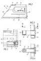
- FIGS. 1 to 4 of the drawings show the embodiment of the electrically operated steam iron according to the invention.
- the steam iron 2o has a housing 39, which can be composed of several parts in a known manner.
- the housing 39 is closed at the bottom by a sole plate 21.
- the Sole plate can be provided in a known manner with a plurality of outlet openings 37, only one of which is shown schematically in FIG. 2 of the drawing. The number and arrangement of the outlet openings is variable.
- the housing 39 On the side opposite the soleplate, the housing 39 has a handle 24. Below this is an adjusting wheel 27 for the temperature control.
- a rotary knob 25 is arranged in a known manner, with which, for example, a continuous regulation of the amount of care steam is possible.
- a pushbutton 4o is provided to the side of the rotary knob 25. By pressing this water spray button, the fabrics to be ironed can be moistened.
- the spray nozzle 26 arranged in the region of the end face of the housing 39 serves this purpose.
- the parts of the electrically operated steam iron 2o which interact with the adjusting wheel 27, the rotary knob 25, the pushbutton 4o and the spray nozzle 26 are known and are therefore neither drawn nor described.
- a water level indicator 28 through which the user can see how much water is still in the water tank 23, which is accommodated in the interior of the housing 39 in a known manner.
- an evaporator chamber 22 Above the sole plate 21 is an evaporator chamber 22, which can likewise have a known design and which, in a further known manner, interacts with the control and regulating devices accommodated in the interior of the housing.
- the water tank 23 has an outlet 36 lying in the region of the rear wall 29 of the housing 39 of the steam iron 2o, which is followed by a decalcifying agent 41 according to the invention.
- an opening 30 is provided in the lower area of the rear wall 29 of the housing 39, through which a holder 31 can be passed.
- the holder is the selected embodiment, an essentially one-piece plastic body, which has a receiving space 33 for the decalcifying agent 41 on its end lying inside the housing 39.
- the bottom of the receiving space 33 is designed as a sieve bottom 35.
- the receiving space 33 is delimited by a circumferential peripheral wall 34 which is open at the top.
- the decalcifying agent 41 is introduced into the receiving space 33. This can either be done in a solid, pressed form or a refill cartridge can be used, that is, one that can be refilled after the decalcifying agent it contains has been used up.
- the holder 31 has two spaced and parallel connectors 42 which are equipped with guide and / or locking elements 43. These interact with the counter catches or counter guides in the region of the boundary wall of the opening 3o of the rear wall 29. It can be tongue and groove. In addition, simple detents and counter detents of known training can also be used. It does not matter whether the catches are attached to the connectors or the boundary walls or vice versa.
- the holder 31 has a viewing window 32.
- the user of the steam iron can see through this viewing window whether the decalcifying agent contained in the receiving space 33 is still effective.
- the side of the peripheral wall 34 facing the viewing window 32 is transparent.
- the decalcifying agent 41 is ineffective when the color changes. It should be mentioned at this point that commercially available chemicals can be used as decalcifying agents.
- the holder 31 can be pulled out of the rear wall 29 in a simple manner by the user.
- the used decalcifying agent is then removed and the receiving space 33 is refilled, leaving the user free to choose whether to use a solid, pressed decalcifying agent or a refill cartridge.
- the softened water from the bottom sieve 35 leaves the receiving space and is then passed on, for example, via supply lines 38.
- the softened water is conveyed and conveyed through e.g. is fed to a drip valve. From there, it can be metered into the evaporation chamber 22.
- the existing supply lines are identified only schematically by 38. The known conveying and metering devices for the softened water are omitted for the sake of simplicity.
- the embodiment shown is only one example of realizing the invention and it is not restricted to this. Rather, many other designs and applications are possible.
- the invention can also be used in other known embodiments of steam irons.
- the decalcifying agents can be configured differently from those shown.
- refill cartridges are used, they can also be adapted to the shape and dimensions of the receiving space in which they are to be accommodated. All commercially available chemicals that soften water can be used as decalcifying agents. When dimensioning the decalcifying agent, care must be taken to ensure that the water can pass through quickly.
- the invention can also be used in other electrically operated household appliances which work with hot water and which therefore have the problem of scaling. It is thought for example of coffee or tea machines or the like.
Description
Die Erfindung bezieht sich auf ein elektrisch betriebenes Dampfbügeleisen mit einem einen Handgriff aufweisenden Gehäuse, dessen untere Öffnung durch eine mit Auslaßöffnungen versehene Sohlenplatte verschlossen ist sowie mit einem Wasserbehälter, einem Aufnahmeraum für ein Entkalkungsmittel, der sich an den Auslaß des Wasserbehälters anschließt und einer damit unter Zwischenschaltung einer Regeleinrichtung verbindbaren Verdampferkammer und mit einer regelbaren Heizeinrichtung.The invention relates to an electrically operated steam iron with a handle housing, the lower opening is closed by a sole plate provided with outlet openings and with a water tank, a receiving space for a decalcifying agent, which connects to the outlet of the water tank and one under Interposition of a control device connectable evaporator chamber and with a controllable heating device.
Derartige elektrisch betriebene Dampfbügeleisen, die in unterschiedlichen Ausführungsformen bekannt sind, benötigen beim bestimmungsgemäßen Gebrauch die Verwendung von Wasser, welches verdampft werden muß. Häufig wird dabei von dem Benutzer Leitungswasser eingesetzt. Solches Leitungswasser ist chemisch gesehen nicht rein. Vielmehr enthält es neben aufgelösten Gasen eine Reihe von Salzen, die aus Böden, Gestein od.dgl. herausgelöst sind. Zu den Salzen, die im Leitungswasser enthalten sind, gehören u.a. Calciumbikarbonet, Calciumsulfat und Magnesiumkarbonat. Zusammenfassend bezeichnet man diese als "Härte" des Wassers. Zur Kennzeichnung der Härte des Wassers ist die Bezeichnung "Härtegrad" in Gebrauch. Je höher der Wert eines Härtegrades ist, umso härter ist das Wasser.Such electrically operated steam irons, which are known in different embodiments, require the use of water, which must be evaporated, when used as intended. Tap water is often used by the user. From a chemical point of view, such tap water is not pure. Rather, in addition to dissolved gases, it contains a number of salts, or the like, from soils, rocks. are detached. The salts contained in tap water include calcium bicarbonate, calcium sulfate and magnesium carbonate. In summary, this is called "hardness" of the water. The term "degree of hardness" is used to indicate the hardness of the water. The higher the value of a degree of hardness, the harder the water.
Bei der Benutzung elektrisch betriebener Dampfbügeleisen spielt die Härte des in den Wasserbehälter eingefüllten Wassers eine wesentliche Rolle und zwar deshalb, weil bei einer Erhitzung von Leitungswasser eine Abscheidung des Wassers in einzelne Bestandteile stattfindet. Ein Teil der abgeschiedenen Bestandteile, insbesondere die Karbonate schlagen sich als sogenannter "Kesselstein" an den wasserführenden Teilen des Dampfbügeleisens nieder. Kesselstein ist aus verschiedenen Gründen unerwünscht. Er wirkt einmal als Wärmeisolator, was sich in einem erhöhten Energieverbrauch niederschlägt. Darüber hinaus können aber Rohre oder durchmesserkleine Leitungen sich mit der Zeit durch Kesselstein völlig zusetzen.When using electrically operated steam irons, the hardness of the water filled into the water tank plays an important role, because when the tap water is heated, the water is separated into individual components. Some of the separated components, in particular the carbonates, are deposited on the water-carrying parts of the steam iron as a "scale". Scale is undesirable for several reasons. It acts as a heat insulator, which translates into increased energy consumption. In addition, however, pipes or small-diameter lines can become completely clogged with scale over time.
In der Praxis läßt sich der Kesselstein durch Säuren beseitigen. Sofern es sich um Kupfer, Messing od.dgl. Metalle handelt, können zum Entfernen von Kesselstein verdünnte Lösungen von Milchsäure oder Essigsäure verwendet werden. Die Hersteller bzw. Verteiler von elektrisch betriebenen Dampfbügeleisen empfehlen daher in aller Regel innerhalb bestimmter Zeitintervalle ein Entkalken. Die Zeitabstände, in denen ein solches Entkalken durchgeführt werden muß, sind aber von dem Härtegrad des benutzten Leitungswassers abhängig.In practice, the scale can be removed by acids. If it is copper, brass or the like. Metals can be used to remove scale from dilute solutions of lactic acid or acetic acid. The manufacturers or distributors of electrically operated steam irons therefore generally recommend descaling within certain time intervals. The time intervals in which such descaling must be carried out depend on the degree of hardness of the tap water used.
Es sind auch sogenannte Entkalkungsanzeigevorrichtungen bekannt, die vielfach auf elektrischer oder elektronischer Basis arbeiten. Sie haben sich in der Praxis nicht durchsetzen können, nicht zuletzt deshalb, weil sie einmal einen erheblichen technischen Aufwand erfordern und zum anderen, weil sie trotzdem nicht das gewünschte, optimale Ergebnis bringen.So-called descaling display devices are also known, which often operate on an electrical or electronic basis. They have not been able to assert themselves in practice, not least because they require considerable technical effort on the one hand and, on the other hand, because they do do not bring the desired, optimal result.
Darüber hinaus gibt es auch mehrere Ausführungsformen von Dampfbügeleisen der eingangs näher gekennzeichneten Art, bei denen ein Entkalkungsmittel des Wassers benutzt wird. Ein solches Dampfbügeleisen ist in der JP-OS 6o-16o997 offenbart. Bei dieser Ausführungsform des Dampfbügeleisens ist im Bereich der Ausflußöffnung des Wasserbehälters ein Entkalkungsmittel angeordnet. Dieses Entkalkungsmittel befindet sich in einem rohrförmigen Verbindungsstück zwischen dem Wasserbehälter und der Verdampferkammer des Dampfbügeleisens. An sich ist es vorteilhaft, ein Entkalkungsmittel im Bereich der Austrittsöffnung des Wasserbehälters anzuordnen, weil dann in die Verdampferkammer nur entkalktes Wasser gelangt. Jedoch hat diese bekannte Ausbildung des Dampfbügeleisens auch Nachteile, einmal bereitet es Schwierigkeiten, das Entkalkungsmittel in das rohrförmige Verbindungsstück einzubringen, weil es in einem verhältnismäßig schwer zugänglichen Bereich des Innenraumes des Gehäuses liegt. Zum anderen ist die im Verbindungsstück unterzubringende Menge an Entkalkungsmittel relativ klein. Der Benutzer dieses bekannten Dampfbügeleisens hat keine Möglichkeit, die Beschaffenheit des Entkalkungsmittels schnell und einfach zu überprüfen. Darüber hinaus ist ein Auswechseln des verbrauchten Entkalkungsmittels schwierig.In addition, there are also several embodiments of steam irons of the type identified in the introduction, in which a decalcifying agent of the water is used. Such a steam iron is disclosed in JP-OS 6o-16o997. In this embodiment of the steam iron, a decalcifying agent is arranged in the region of the outflow opening of the water tank. This decalcifying agent is located in a tubular connector between the water tank and the evaporator chamber of the steam iron. As such, it is advantageous to arrange a decalcifying agent in the area of the outlet opening of the water container, because then only decalcified water gets into the evaporator chamber. However, this known design of the steam iron also has disadvantages. First, it is difficult to introduce the decalcifying agent into the tubular connecting piece because it lies in a relatively difficult to access area of the interior of the housing. On the other hand, the amount of decalcifying agent to be accommodated in the connector is relatively small. The user of this known steam iron has no possibility of checking the nature of the decalcifying agent quickly and easily. In addition, changing the used decalcifying agent is difficult.
Durch die GB-PS 1 o22 697 ist ein Dampfbügeleisen bekanntgeworden, bei dem ein Entkalkungsmittel im Bereich des Einlasses des Wasserbehälters angeordnet ist, wobei das Entkalkungsmittel zum Erkennen seiner Beschaffenheit von außen durch ein Sichtfenster sichtbar ist. Bei diesem Dampfbügeleisen befindet sich das Entkalkungsmittel in einem Behälter, der in einer Ausnehmung des Handgriffes des Dampfbügeleisens untergebracht ist. Diese Ausnehmung ist zur Außenseite des Handgriffes hin durch einen entfernbaren Wandungsteil verschlossen, der seinerseits das Sichtfenster aufweist. Nachteilig ist dabei, daß das Entkalkungsmittel im Bereich des Einlasses des Wasserbehälters angeordnet ist. Dadurch gestaltet sich das Befüllen des Wasserbehälters schwierig, weil das Durchfließen des Wassers durch das Entkalkungsmittel langwierig ist. Darüber hinaus ist das Sichtfenster ein Bestandteil eines Teilstückes des Handgriffes des Dampfbügeleisens. Der das Entkalkungsmittel aufnehmende Behälter hat keinen durchsichtigen Bereich.From GB-
Die DE 3 o33 964 A1 zeigt ein elektrisch beheiztes Dampfbügeleisen, in dessen Wasserbehälter ein Enthärter (ein Entkalkungsmittel) angeordnet ist, wobei der Enthärter durch eine siebartige, wasserdurchlässige Wandung vom Inneren des Wasserbehälters getrennt ist. Dabei ist auch vorgesehen, den Enthärter in einer Patrone mit siebartiger Wandung unterzubringen. Eine solche Patrone ist mit ihrer wasserdurchlässigen Wandung - die Wasserbehälterwandung durchdringend - im Wasserbehälterinneren angeordnet. Der wasserundurchlässige Patronenboden ist dabei mit dem Außenmantel des Wasserbehälters lösbar verbunden. Bei einer konkreten Ausführungsform ist die Patrone in die Behälterwandung des Wasserbehälters geschraubt, und es ist zwischen der Patrone und dem Wasserbehälter eine Dichtung vorgesehen. Es ist bei diesem bekannten Dampfbügeleisen auch offenbart, eine transluzente Tankwandung zu benutzen, um dem Benutzer die Möglichkeit zu geben, feststellen zu können, ob der Enthärter verbraucht ist. Dies kann dadurch festgestellt werden, daß ein Farbumschlag des Enthärters oder eines beigemischten Indikators erfolgt. Bei dieser bekannten Ausführungsform des Dampfbügeleisens erfolgt keine Anordnung der den Enthärter enthaltenden Patrone im Bereich des Auslasses des Wasserbehälters. Vielmehr ragt die Patrone frei in den Wasserbehälter hinein, derart, daß sie vom Wasser völlig umspült werden kann.DE 3 o33 964 A1 shows an electrically heated steam iron, in the water tank of which a softener (a decalcifying agent) is arranged, the softener being separated from the interior of the water tank by a sieve-like, water-permeable wall. It is also intended to accommodate the softener in a cartridge with a sieve-like wall. Such a cartridge is arranged with its water-permeable wall - penetrating the water tank wall - inside the water tank. The water-impermeable cartridge bottom is detachably connected to the outer jacket of the water tank. In a specific embodiment, the cartridge is screwed into the container wall of the water container and a seal is provided between the cartridge and the water container. It is also disclosed in this known steam iron to use a translucent tank wall to give the user the opportunity to be able to determine whether the softener has been used up. This can be determined by a change in color of the softener or an added indicator. In this known embodiment of the steam iron, the cartridge containing the softener is not arranged in the region of the outlet of the water tank. Rather, the cartridge projects freely into the water tank in such a way that it can be completely washed around by the water.
Bei einer Alternativlösung des Dampfbügeleisens nach DE 3 o33 964 A1 ist vorgesehen, die Enthärtermasse lose in den Wasserbehälter zu geben. Behältereinlauf und Behälterauslauf sind dabei durch Siebe verschlossen. Diese sollen einmal verhindern, daß der Enthärter in die Verdampfungskammer gelangt und zum anderen sollen sie dafür sorgen, daß bei Bedarf der Wasserbehälterinhalt ausgeleert werden kann, ohne daß der Enthärter verlorengeht. Zur Entfernung des verbrauchten Enthärters ist in der Behälterwand eine verschließbare Öffnung vorgesehen.In an alternative solution of the steam iron according to DE 3 o33 964 A1, it is provided that the softener mass is added loosely to the water tank. The container inlet and outlet are closed by sieves. On the one hand, these are intended to prevent the softener from entering the evaporation chamber and, on the other hand, they are to ensure that the contents of the water tank can be emptied if necessary without the softener being lost. A closable opening is provided in the container wall to remove the used softener.
Eine Anordnung des Entkalkungsmittels im Bereich des Auslasses eines Wasserbehälters ist aus der DE-A 3 o14 493 für ein Haushaltsgerät mit Heißwasserbeiter, insbesondere einer Kaffeemaschine bekannt.An arrangement of the decalcifying agent in the area of the outlet of a water container is known from DE-A 3014493 for a household appliance with a hot water heater, in particular a coffee machine.
Durch die US-PS 4 565 o19 ist ein mehrteiliges Gerät bekanntgeworden, welches beim Bügeln von Textilien benutzt werden soll. Zu diesem Gerät gehört ein kastenförmiges Gehäuse, dessen obere Seite zum Aufstellen eines Dampfbügeleisens verwendet werden soll. Auf der Oberseite des Gehäuses ist ein Wasserbehälter derart angeordnet, daß sein Verschwenken in zwei Endlagen möglich ist. In der wirksamen einen Endlage kann dem Wasserbehälter Wasser entnommen werden, was in der anderen Endlage nicht möglich ist. In der wirksamen Endlage des Wasserbehälters kann das Wasser durch eine Öffnung in seiner Wand abfließen. Es gelangt über nachgeschaltete Führungs- und Regeleinrichtungen in eine Rohrleitung, deren anderes Ende an eine Patrone angeschlossen ist, die mit einem Entkalkungsmittel bzw. mit einem Wasserweichmacher gefüllt ist. In der Patrone wird das Wasser behandelt und kann dann von dort entkalkt weitergeleitet werden. Oberhalb der Patrone befindet sich in der Oberseite des Gehäuses ein Sichtfenster. Durch dieses besteht für den Benutzer des Gerätes die Möglichkeit der Überwachung des Entkalkungsmittels der Patrone. Das Dampfbügeleisen selbst hat bei dem Gerät nach der US-PS 4 565 o19 weder eine Entkalkungspatrone noch ein Sichtfenster. Diese Teile sind vielmehr in dem kastenförmigen, separaten Gehäuse untergebracht, auf dem das Dampfbügeleisen abgestellt werden kann.From US-PS 4 565 o19 a multi-part device has become known, which is to be used for ironing textiles. This device includes a box-shaped housing, the upper side of which is to be used for setting up a steam iron. A water container is arranged on the top of the housing in such a way that it can be pivoted into two end positions is. In the effective one end position, water can be taken from the water tank, which is not possible in the other end position. In the effective end position of the water tank, the water can drain through an opening in its wall. It passes through downstream management and control devices into a pipeline, the other end of which is connected to a cartridge which is filled with a decalcifying agent or with a water softener. The water is treated in the cartridge and can then be decalcified from there. A viewing window is located above the cartridge in the top of the housing. This enables the user of the device to monitor the descaling agent in the cartridge. The steam iron itself has neither a decalcification cartridge nor a viewing window in the device according to US Pat. No. 4,565,019. Rather, these parts are housed in the box-shaped, separate housing on which the steam iron can be placed.
Die Erfindung will die bekannten Dampfbügeleisen nach der JP-OS 6o-16o997 weiter verbessern.The invention aims to further improve the known steam iron according to JP-OS 6o-16o997.
Der Erfindung liegt die Aufgabe zugrunde, elektrisch betriebene Dampfbügeleisen dieser Art so weiter zu verbessern, daß ein leichtes Auswechseln des Entkalkungsmittels aus dem Aufnahmeraum Im Gehäuse des Dampfbügeleisens möglich ist, wobei zugleich Teile des Aufnahmeraumes zum Erkennen der Beschaffenheit des Entkalkungsmittels dienen sollen.The invention has for its object to further improve electrically operated steam irons of this type so that an easy replacement of the decalcifying agent from the receiving space is possible in the housing of the steam iron, parts of the receiving space should also serve to recognize the nature of the decalcifying agent.
Erfindungsgemäß ist diese Aufgabe dadurch gelöst, daß das Dampfbügeleisen ein Sichtfenster zum Erkennen der Beschaffenheit des Entkalkungsmittels von außen, insbesondere seines Farbzustandes aufweist und der Aufnahmeraum eine wenigstens bereichsweise durchsichtige Umfangswand aufweist, durch welche das Entkalkungsmittel sichtbar ist und daß der Aufnahmeraum für das Entkalkungsmittel an einem Halter angeordnet ist, der einen Durchbruch der Rückwand des Dampfbügeleisens durchgreift und das Sichtfenster trägt, welches den Durchbruch verschließt und daß der Halter Führungs- und Rastelemente zu seiner lösbaren Anbringung an der Rückwand des Dampfbügeleisens aufweist.According to the invention, this object is achieved in that the steam iron has a viewing window for recognizing the nature of the decalcifying agent from the outside, in particular of its color state and the receiving space has an at least partially transparent peripheral wall through which the decalcifying agent is visible and that the receiving space for the decalcifying agent is arranged on a holder which penetrates an opening in the rear wall of the steam iron and carries the viewing window , which closes the opening and that the holder has guide and locking elements for its detachable attachment to the rear wall of the steam iron.
Die erfindungsgemäße Ausbildung eines elektrisch betriebenen Dampfbügeleisens bringt gegenüber der obengenannten japanischen Offenlegungsschrift beachtliche Vorteile. Der Benutzer des Dampfbügeleisens hat jederzeit die Möglichkeit - was an sich bekannt ist - zu kontrollieren, ob das Entkalkungsmittel noch wirksam ist. Er kann durch das Sichtfenster die Beschaffenheit des Entkalkungsmittels feststellen, insbesondere ob ein Farbumschlag stattgefunden hat.The inventive design of an electrically operated steam iron brings considerable advantages over the above-mentioned Japanese patent application. The user of the steam iron has the possibility at any time - as is known per se - to check whether the decalcifying agent is still effective. Through the viewing window, he can determine the nature of the decalcifying agent, in particular whether the color has changed.
Ein weiterer Vorteil der Erfindung besteht darin, daß der Aufnahmeraum für das Entkalkungsmittel selbst bereichsweise eine durchsichtige Umfangswand aufweist, durch welche das Entkalkungsmittel sichtbar ist.Another advantage of the invention is that the receiving space for the decalcifying agent itself has a transparent peripheral wall in some areas, through which the decalcifying agent is visible.
Da der Aufnahmeraum für das Entkalkungsmittel an einem Halter angeordnet ist, der einen Durchbruch der Gehäusewand des Dampfbügeleisens durchgreift und das Sichtfenster trägt, welches den Durchbruch verschließt, ist sowohl ein leichtes Anbringen als auch ein Abnehmen des Aufnahmeraumes am bzw. vom Gehäuse des Dampfbügeleisens möglich.Since the receiving space for the decalcifying agent is arranged on a holder which passes through an opening in the housing wall of the steam iron and carries the viewing window which closes the opening, it is both easy to attach and remove the receiving space on or from the housing steam iron possible.
Es empfiehlt sich, den Boden des Aufnahmeraumes für das Entkalkungsmittel als Bodensieb auszubilden, durch welches das enthärtete Wasser der Verdampferkammer zuführbar ist.It is recommended to design the bottom of the receiving space for the decalcifying agent as a bottom sieve through which the softened water can be fed to the evaporator chamber.
Zweckmäßig ist es, daß das durch das Bodensieb des Aufnahmeraumes austretende enthärtete Wasser einer Fördereinrichtung, wie einer Wasserpumpe, einer Dosiereinrichtung, wie einem Tropfventil, zuführbar ist und von dort dosiert in die Verdampferkammer des Dampfbügeleisens gelangt.It is expedient that the softened water emerging through the bottom sieve of the receiving space can be fed to a conveying device, such as a water pump, a metering device, such as a drip valve, and from there reaches the evaporator chamber of the steam iron in metered fashion.
Es empfiehlt sich, daß die Umfangswand des Aufnahmeraumes über Verbinder mit dem Sichtfenster verbunden ist und daß die Verbinder und die Begrenzungswandungen des Durchbruches der Rückwand die zusammenwirkende Führungs- und/oder Rastelemente aufweisen.It is recommended that the peripheral wall of the receiving space is connected to the viewing window via connectors and that the connectors and the boundary walls of the opening in the rear wall have the cooperating guide and / or locking elements.
Auf der Zeichnung ist die Erfindung in einem Ausführungsbeispiel dargestellt und zwar zeigen:
- Fig. 1
- in Seitenansicht ein erfindungsgemäßes elektrisch betriebenes Dampfbügeleisen mit integriertem Wasserbehälter,
- Fig. 2
- im vergrößerten Maßstab, teilweise weggebrochen, teilweise in Ansicht und teilweise weggeschnitten den rückwärtigen, das Entkalkungsmittel aufweisenden Teil des Dampfbügeleisens gemäß der Fig. 1 der Zeichnung,
- Fig. 3
- im nochmals vergrößerten Maßstab und im Schnitt, teilweise weggebrochen, denjenigen Teil der Rückwand des Dampfbügeleisens nach der Fig. 1, in dem der Halter für das Entkalkungsmittel angebracht ist und
- Fig. 4
- einen Schnitt durch die Rückwand des Bügeleisens entlang der Linie IV-IV der Fig. 3.
- Fig. 1
- in side view an electrically operated steam iron according to the invention with an integrated water tank,
- Fig. 2
- on an enlarged scale, partly broken away, partly in view and partly cut away, the rear part of the steam iron having the decalcifying agent according to FIG. 1 of the drawing,
- Fig. 3
- on a further enlarged scale and in section, partially broken away, that part of the rear wall of the steam iron according to FIG. 1 in which the holder for the decalcifying agent is attached and
- Fig. 4
- a section through the rear wall of the iron along the line IV-IV of Fig. 3rd
Es sei zunächst erwähnt, daß in den Figuren der Zeichnungen nur diejenigen Teile eines elektrisch betriebenen Dampfbügeleisens wiedergegeben sind, die für das Verständnis der Erfindung Bedeutung haben. So fehlen insbesondere die Regel- und Steuereinrichtungen des Dampfbügeleisens und auch die elektrischen Anschlüsse sowie die Heizung für die Sohlenplatte. Ferner sind in den Figuren der Zeichnungen Fördereinrichtungen, wie Wasserpumpen, Tropfventile od.dgl. nicht mit dargestellt. Von diesen sind teilweise lediglich die Handhaben bzw. Bedienungsknöpfe ersichtlich. Im übrigen können alle in den Zeichnungen fehlenden Teile einen an sich bekannten Aufbau haben und in ebenfalls an sich bekannter Weise im oder am Bügeleisen angeordnet werden. Dies gilt auch für die elektrische Versorgungsleitung.It should first be mentioned that only those parts of an electrically operated steam iron are shown in the figures of the drawings which are important for understanding the invention. In particular, the regulating and control devices of the steam iron and also the electrical connections and the heating for the soleplate are missing. Furthermore, conveyor devices such as water pumps, drip valves or the like are in the figures of the drawings. not shown. Of these, only the handles or control buttons are partially visible. In addition, all parts missing in the drawings can have a structure known per se and can be arranged in or on the iron in a manner known per se. This also applies to the electrical supply line.
In den Figuren 1 bis 4 der Zeichnungen ist die erfindungsgemäße Ausführungsform des elektrisch betriebenen Dampfbügeleisens dargestellt. Dieses ist generell mit 2o bezeichnet,. Das Dampfbügeleisen 2o hat ein Gehäuse 39, das in bekannter weise aus mehreren Teilen zusammengesetzt sein kann. Das Gehäuse 39 ist nach unten hin durch eine Sohlenplatte 21 verschlossen. Die Sohlenplatte kann in bekannter Weise mit einer Vielzahl von Auslaßöffnungen 37 versehen sein, von denen in der Fig. 2 der Zeichnung nur eine schematisch dargestellt ist. Die Anzahl und die Anordnung der Auslaßöffnungen ist variabel. Auf der der Sohlenplatte gegenüberliegenden Seite hat das Gehäuse 39 einen Handgriff 24. Unterhalb desselben liegt ein Stellrad 27 für die Temperaturregelung. In Höhe der Oberkante des Handgriffes 24 ist in bekannter Weise ein Drehknopf 25 angeordnet, mit dem z.B. eine stufenlose Regulierung der Pflegedampfmenge möglich ist. Seitlich neben dem Drehknopf 25 ist eine Drucktaste 4o vorgesehen. Durch Druck auf diese Wassersprühtaste ist eine Befeuchtung der zu bügelnden Stoffe möglich. Dazu dient die im Bereich der Stirnfläche des Gehäuses 39 angeordnete Sprühdüse 26. Die mit dem Stellrad 27 , dem Drehknopf 25, der Drucktaste 4o und der Sprühdüse 26 zusammenwirkenden Teile des elektrisch betriebenen Dampfbügeleisens 2o sind bekannt und daher weder gezeichnet noch beschrieben.FIGS. 1 to 4 of the drawings show the embodiment of the electrically operated steam iron according to the invention. This is generally designated 2o. The steam iron 2o has a
Im Bereich der Seitenwand des Gehäuses 39 befindet sich eine Wasserstandsanzeige 28, durch die der Benutzer erkennen kann, wie-viel Wasser sich noch in dem Wasserbehälter 23 befindet, der im Inneren des Gehäuses 39 in bekannter Weise untergebracht ist. Oberhalb der Sohlenplatte 21 liegt eine Verdampferkammer 22, die ebenfalls eine bekannte Ausbildung aufweisen kann und in weiter bekannter Weise mit den im Inneren des Gehäuses untergebrachten Steuer- und Regeleinrichtungen zusammenwirkt.In the area of the side wall of the
Der Wasserbehälter 23 hat im Bereich der Rückwand 29 des Gehäuses 39 des Dampfbügeleisens 2o liegend einen Auslaß 36, dem erfindungsgemäß ein Entkalkungsmittel 41 nachgeschaltet ist.The
Um das Entkalkungsmittel 41 in den Bereich des Auslasses 36 des Wasserbehälters 23 bringen zu können, ist in dem unteren Bereich der Rückwand 29 des Gehäuses 39 ein Durchbruch 3o vorgesehen, durch den ein Halter 31 hindurchgeführt werden kann. Bei dem Halter handelt es sich um gewählten Ausführungsbeispiel um einen im wesentlichen einstückigen Kunststoffkörper, der auf seinem im Inneren des Gehäuses 39 liegenden Ende einen Aufnahmeraum 33 für das Entkalkungsmittel 41 aufweist. Der Boden des Aufnahmeraumes 33 ist als Siebboden 35 ausgebildet. Der Aufnahmeraum 33 wird von einer umlaufenden Umfangswand 34 eingegrenzt, die nach oben hin offen ist. In den Aufnahmeraum 33 wird das Entkalkungsmittel 41 eingebracht. Dies kann entweder in fester, gepreßter Form geschehen oder aber es kann eine Refillpatrone eingesetzt werden, also eine solche, die nach Verbrauch des in ihm enthaltenen Entkalkungsmittels wieder neu gefüllt werden kann.In order to be able to bring the
Die Fig. 4 läßt erkennen, daß der Halter 31 zwei im Abstand und parallel zueinander angeordnete Verbinder 42 aufweist, die mit Führungs- und/oder Rastelementen 43 ausgerüstet sind. Diese wirken mit den Gegenrasten bzw. Gegenführungen im Bereich der Begrenzungswand des Durchbruches 3o der Rückwand 29 zusammen. Es kann sich dabei um Feder und Nut handeln. Daneben können aber auch einfache Rasten und Gegenrasten bekannter Ausbildung benutzt werden. Es ist dabei gleichgültig, ob die Rasten an den Verbindern oder an den Begrenzungswandungen angebracht sind oder umgekehrt.4 shows that the
An dem aus dem Durchbruch herausragenden Ende hat der Halter 31 ein Sichtfenster 32. Durch dieses Sichtfenster hindurch kann der Benutzer des Dampfbügeleisens erkennen, ob das in dem Aufnahmeraum 33 enthaltene Entkalkungsmittel noch wirksam ist. Dazu ist die dem Sichtfenster 32 zugekehrte Seite der Umfangswand 34 durchsichtig. Das Entkalkungsmittel 41 ist dann unwirksam, wenn ein Farbumschlag erfolgt. Es sei an dieser Stelle erwähnt, daß als Entkalkungsmittel im Handel befindliche Chemikalien eingesetzt werden können.At the end protruding from the opening, the
Nach dem Verbrauch des Entkalkungsmittels 33 kann der Halter 31 in einfacher Weise vom Benutzer aus der Rückwand 29 herausgezogen werden. Es erfolgt dann das Entfernen des verbrauchten Entkalkungsmittels und das Neufüllen des Aufnahmeraumes 33, wobei es dem Benutzer freisteht, ob er ein festes gepreßtes Entkalkungsmittel oder eine Refillpatrone benutzt.After the
Es bleibt noch nachzutragen, daß das enthärtete Wasser aus dem Bodensieb 35 den Aufnahmeraum verläßt und dann beispielsweise über Versorgungsleitungen 38 weitergeleitet wird. Zweckmäßig ist es aber, wenn das enthärtete Wasser über Förder- und Steuereinrichtungen z.B. einem Tropfventil zugeleitet wird. Von dort aus kann es dosiert in die Verdampfungskammer 22 überführt werden. In der Fig. 2 der Zeichnung sind die vorhandenen Versorgungsleitungen nur schematisch mit 38 gekennzeichnet. Die an sich bekannten Förder- und Dosiereinrichtungen für das enthärtete Wasser sind der Einfachheit halber fortgelassen.It remains to be added that the softened water from the
Wie bereits erwähnt, ist die dargestellte Ausführung nur eine beispielsweise Verwirklichung der Erfindung und diese nicht darauf beschränkt. Vielmehr sind noch mancherlei andere Ausführungen und Anwendungen möglich. Insbesondere kann die Erfindung auch bei anderen an sich bekannten Ausführungsformen von Dampfbügeleisen eingsetzt werden. Ferner können die Entkalkungsmittel eine andere als die dargestellte Ausbildung erhalten. Insbesondere ist eine Anpassung an den jeweils vorhandenen Aufnahmeraum möglich, soweit es sich um kompaktförmige, feste Entkalkungsmittel handelt. Soweit Refillpatronen benutzt werden, können diese ebenfalls der Gestalt und den Abmessungen des Aufnahmeraumes angepaßt werden, in denen sie untergebracht werden sollen. Als Entkalkungsmittel lassen sich alle im Handel befindlichen Chemikalien benutzen, die dem Enthärten von Wasser dienen. Bei der Dimensionierung des Entkalkungsmittels ist darauf zu achten, daß ein zügiger Durchlaß des Wassers erzielt wird. Darüber hinaus kann die Erfindung auch bei anderen elektrisch betriebenen Haushaltsgeräten eingesetzt werden, die mit heißem Wasser arbeiten und bei denen damit das Problem des Ansetzens von Kesselstein besteht. Gedacht ist z.B. an Kaffee- oder Teeautomaten od.dgl.As already mentioned, the embodiment shown is only one example of realizing the invention and it is not restricted to this. Rather, many other designs and applications are possible. In particular, the invention can also be used in other known embodiments of steam irons. Furthermore, the decalcifying agents can be configured differently from those shown. In particular, it is possible to adapt to the respective receiving space provided that it is compact, solid decalcifying agent. If refill cartridges are used, they can also be adapted to the shape and dimensions of the receiving space in which they are to be accommodated. All commercially available chemicals that soften water can be used as decalcifying agents. When dimensioning the decalcifying agent, care must be taken to ensure that the water can pass through quickly. In addition, the invention can also be used in other electrically operated household appliances which work with hot water and which therefore have the problem of scaling. It is thought for example of coffee or tea machines or the like.
- 2o2o
- - Dampfbügeleisen- Steam iron
- 2121
- - Sohlenplatte (von 2o)- sole plate (from 2o)
- 2222
- - Verdampferkammer (von 2o)- Evaporator chamber (from 2o)
- 2323
- - Wasserbehälter- water tank
- 2424th
- - Handgriff- handle
- 2525th
- - Drehknopf- rotary knob
- 3636
- - Sprühdüse- spray nozzle
- 2727th
- - Stellrad (für Temperaturregelung)- setting wheel (for temperature control)
- 2828
- - Wasserstandsanzeige (für 23)- water level indicator (for 23)
- 2929
- - Rückwand (von 2o)- rear wall (from 2o)
- 3o3o
- - Durchbruch (in 29)- breakthrough (in 29)
- 3131
- - Halter- holder
- 3232
- - Sichtfenster- viewing window
- 3333
- - Aufnahmeraum für Entkalkungsmittel- Room for descaling agents
- 3434
- - Umfangswand( von 33)- peripheral wall (of 33)
- 3535
- - Bodensieb- Bottom strainer
- 3636
- - Auslaß (von 23)- outlet (of 23)
- 3737
- - Auslaßöffnung (in 21)- outlet opening (in 21)
- 3838
- - Verbindungsleitung- connecting line
- 3939
- - Gehäuse (von 2o)- Housing (from 2o)
- 4o4o
- - Drucktaste- push button
- 4141
- - Entkalkungsmittel- descaling agent
- 4242
- - Verbinder (an 31)- connector (to 31)
- 4343
- - Führungs- und/oder Rastelemente- Guide and / or locking elements
Claims (4)
- An electrically operated steam iron (20) comprising a housing which has a handle (24) and the lower opening of which is closed by a sole plate provided with outlet openings, and a water tank, a receiving space (33) for a decalcification agent (41), which connects to the outlet (36) of the water tank (23), and an evaporator chamber which can be connected thereto with the interposition of a regulating device, and a regulatable heating means, characterised in that the steam iron (20) has a sight window (32) for observing the condition of the decalcification agent (41) from the outside, in particular its colour condition, and the receiving space (33) has a peripheral wall (34) which is transparent at least in a region-wise manner and through which the decalcification agent (41) is visible, and that the receiving space (33) for the decalcification agent (41) is arranged on a holder (31) which engages through an opening (30) in the rear wall (29) of the steam iron (20) and carries the sight window (32) which closes the opening (30), and that the holder (31) has guide and retaining elements (43) for releasably mounting same to the rear wall (29) of the steam iron (20).
- A steam iron according to claim 1 characterised in that the bottom of the receiving space (33) for the decalcification agent (41) is in the form of a bottom sieve (35) through which the softened water can be passed to the evaporator chamber (22).
- A steam iron according to claim 1 or claim 2 characterised in that the softened water which issues through the bottom sieve (35) of the receiving space (33) can be passed to a conveyor means such as a water pump, a metering means such as a drip valve, and from there passes in a metered fashion into the evaporator chamber (22) of the steam iron (20).
- A steam iron according to one or more of the preceding claims characterised in that the peripheral wall (34) of the receiving space (35) is connected to the sight window (32) by way of connectors (42) and that the connectors (42) and the boundary walls of the opening (30) in the rear wall (29) have the co-operating guide and/or retaining elements (43).
Priority Applications (1)
| Application Number | Priority Date | Filing Date | Title |
|---|---|---|---|
| EP92103138A EP0489714B1 (en) | 1987-09-05 | 1988-06-04 | Electric steam iron |
Applications Claiming Priority (2)
| Application Number | Priority Date | Filing Date | Title |
|---|---|---|---|
| DE3729800 | 1987-09-05 | ||
| DE19873729800 DE3729800A1 (en) | 1987-09-05 | 1987-09-05 | ELECTRICALLY OPERATED STEAM IRON |
Related Child Applications (1)
| Application Number | Title | Priority Date | Filing Date |
|---|---|---|---|
| EP92103138.1 Division-Into | 1988-06-04 |
Publications (2)
| Publication Number | Publication Date |
|---|---|
| EP0306623A1 EP0306623A1 (en) | 1989-03-15 |
| EP0306623B1 true EP0306623B1 (en) | 1992-09-09 |
Family
ID=6335338
Family Applications (2)
| Application Number | Title | Priority Date | Filing Date |
|---|---|---|---|
| EP88108964A Expired - Lifetime EP0306623B1 (en) | 1987-09-05 | 1988-06-04 | Electric steam iron |
| EP92103138A Expired - Lifetime EP0489714B1 (en) | 1987-09-05 | 1988-06-04 | Electric steam iron |
Family Applications After (1)
| Application Number | Title | Priority Date | Filing Date |
|---|---|---|---|
| EP92103138A Expired - Lifetime EP0489714B1 (en) | 1987-09-05 | 1988-06-04 | Electric steam iron |
Country Status (4)
| Country | Link |
|---|---|
| US (1) | US4893422A (en) |
| EP (2) | EP0306623B1 (en) |
| JP (1) | JP2681376B2 (en) |
| DE (1) | DE3729800A1 (en) |
Families Citing this family (44)
| Publication number | Priority date | Publication date | Assignee | Title |
|---|---|---|---|---|
| DE3918561C2 (en) * | 1989-06-07 | 1997-09-11 | Brita Wasserfilter | Water treatment device |
| FR2648485B1 (en) * | 1989-06-08 | 1991-11-15 | Seb Sa | INCLINED TANK IRON |
| FR2648163B1 (en) * | 1989-06-08 | 1991-10-18 | Seb Sa | IRON WITH DEMINERALIZING CARTRIDGE |
| FR2653455A1 (en) * | 1989-10-20 | 1991-04-26 | Seb Sa | Water container for (pressing) iron and iron including such a container |
| FR2663052B1 (en) * | 1990-06-11 | 1992-09-04 | Seb Sa | ELECTRIC IRON WITH DEMINERALIZING CARTRIDGE AND IMPROVED WATER TANK. |
| US5068030A (en) * | 1990-11-09 | 1991-11-26 | Oxford Science Industrial Co., Ltd. | Water filtering sterilizing and heating apparatus |
| FR2683218B1 (en) * | 1991-10-31 | 1994-09-02 | Moulinex Sa | REMOVABLE DEMINERALIZATION CARTRIDGE. |
| IT1264522B (en) * | 1992-01-21 | 1996-10-02 | WATER MEASURE FOR STEAM IRON WITH TRIPLE FUNCTION. | |
| DE69320843T2 (en) * | 1992-01-27 | 1999-03-25 | Seb Sa | Steam iron with a cartridge for treating water and / or ironing textiles |
| DE4203414A1 (en) * | 1992-02-06 | 1993-08-12 | Braun Ag | STEAM IRON WITH REPLACEABLE FILTER INSERT |
| SG49330A1 (en) * | 1993-02-08 | 1998-05-18 | Koninkl Philips Electronics Nv | Steam iron |
| DK47493D0 (en) * | 1993-04-27 | 1993-04-27 | Novo Nordisk As | METHOD OF PRODUCING CHEESE |
| US5409619A (en) * | 1993-08-23 | 1995-04-25 | Reckitt & Colman Inc. | Ironing aid composition |
| US6163990A (en) * | 1997-10-13 | 2000-12-26 | Matsushita Electric Industrial Co., Ltd. | Steam iron with scale deposit repression |
| DE69910171T2 (en) * | 1998-09-22 | 2004-06-17 | Koninklijke Philips Electronics N.V. | STEAM IRON WITH SCALING INDICATOR |
| ES2168891B1 (en) * | 1999-01-21 | 2003-11-16 | Krainel Sa | DECALCIFIER DEVICE FOR ELECTRIC STEAM IRONS. |
| SG81338A1 (en) * | 1999-12-17 | 2001-06-19 | Koninkl Philips Electronics Nv | Water-processing domestic appliance with assembly for de-ionizing water |
| EP1174539B1 (en) * | 2000-07-19 | 2004-10-20 | Euroflex S.r.l. | Professional steam iron with removable rear cold water tank |
| WO2006040556A1 (en) * | 2004-10-13 | 2006-04-20 | Kenwood Limited | Steaming appliances comprising water-treatment means |
| GB2419607A (en) * | 2004-10-26 | 2006-05-03 | Kenwood Marks Ltd | Steam station with water filter |
| WO2006070327A1 (en) * | 2004-12-28 | 2006-07-06 | Koninklijke Philips Electronics N.V. | Water tank for use in a steam ironing device |
| FR2882765B1 (en) * | 2005-03-07 | 2007-04-27 | Rowenta Werke Gmbh Ges Mit Bes | APPARATUS FOR IRONING OR IRISHING THE LAUNDRY COMPRISING AN ADDITIVE RESERVOIR |
| GB0511943D0 (en) | 2005-06-13 | 2005-07-20 | Reckitt Benckiser Uk Ltd | Device |
| US7390413B2 (en) | 2005-11-30 | 2008-06-24 | General Electric Company | Water softener system and method |
| US7303512B1 (en) * | 2006-05-23 | 2007-12-04 | Tucker Toys, Inc. | Pogo ball |
| KR100735707B1 (en) * | 2006-09-29 | 2007-07-06 | 엘지전자 주식회사 | Laundry dryer and method for controlling the same |
| EP1911874A1 (en) * | 2006-10-09 | 2008-04-16 | Koninklijke Philips Electronics N.V. | Soleplate for an iron |
| EP1911873A1 (en) * | 2006-10-09 | 2008-04-16 | Koninklijke Philips Electronics N.V. | Ironing shoe |
| BRPI0807386A2 (en) * | 2007-02-28 | 2014-05-20 | Koninkl Philips Electronics Nv | VAPORIZATION SYSTEM, AND IRONING DEVICE |
| GB2451889B (en) * | 2007-08-16 | 2012-04-25 | Danakim Invest Ltd | Apparatus for treating the skin with steam |
| ES2371736T3 (en) * | 2008-04-07 | 2012-01-09 | Nestec S.A. | DEVICE FOR THE PREPARATION OF DRINKS WITH THE INRUSTRATION ELIMINATION SYSTEM ONLINE AND THE INCRUSTATION ELIMINATION METHOD USING SUCH SYSTEM. |
| EP2116516B1 (en) * | 2008-05-09 | 2014-03-12 | ELECTROLUX PROFESSIONAL S.p.A. | Machine with water heating means and anti-scale device |
| IT1395081B1 (en) * | 2009-07-23 | 2012-09-05 | Unitekno Societa Per Azioni | DEVICE FOR THE DOSED TRANSFER OF FILTERED AND SOFTENED WATER TO THE STEAM BOILERS OF STEAM APPLIANCES. |
| CN102268812A (en) * | 2010-10-22 | 2011-12-07 | 上海市第一中学 | Steam iron with filtering function |
| ES2391679B1 (en) * | 2010-11-12 | 2013-11-22 | Bsh Electrodomésticos España, S.A. | Domestic appliance, especially steam iron. |
| FR2981371B1 (en) * | 2011-10-18 | 2015-02-06 | Seb Sa | IRON IRON COMPRISING A VAPORIZING CHAMBER CONNECTED TO A TARTAR RECOVERY CAVITY COMPRISING A DESCALING ORIFICE |
| FR2981372B1 (en) * | 2011-10-18 | 2013-11-01 | Seb Sa | IRON IRON COMPRISING A VAPORIZING CHAMBER CONNECTED TO A TARTAR RECOVERY CAVITY COMPRISING A DESCALING ORIFICE |
| FR3005665B1 (en) * | 2013-05-16 | 2015-04-24 | Seb Sa | IRONING APPARATUS COMPRISING A WATER TREATMENT DEVICE |
| FR3010420B1 (en) * | 2013-09-10 | 2015-09-25 | Seb Sa | IRONING HOUSEHOLD APPLIANCE COMPRISING A FILTER FOR RETAINING VAPOR TRANSPARENT TARTRE PARTICLES |
| FR3033339B1 (en) * | 2015-03-03 | 2017-02-24 | Seb Sa | IRONING APPLIANCE COMPRISING A TANK COMPRISING ANTI-TARIFF AGENT AND A STEAM DISTRIBUTION CIRCUIT COMPRISING A FILTER |
| ITUA20162801A1 (en) * | 2016-04-21 | 2017-10-21 | De Longhi Appliances Srl | BOILER |
| CN106436250B (en) * | 2016-10-18 | 2018-12-11 | 宁波凯波集团有限公司 | Steam and dry iron vaporization chamber impurity collection structure |
| CN106521912B (en) * | 2016-11-21 | 2019-01-18 | 宁波凯波集团有限公司 | The assembling structure of steam and dry iron vaporization chamber impurity collection box |
| JP2019209020A (en) * | 2018-06-08 | 2019-12-12 | パナソニックIpマネジメント株式会社 | Steam generation device and steam iron |
Citations (3)
| Publication number | Priority date | Publication date | Assignee | Title |
|---|---|---|---|---|
| US4400279A (en) * | 1978-10-07 | 1983-08-23 | Dornier System Gmbh | Process and equipment for rendering visible the charge of ion exchangers |
| JPS60160997A (en) * | 1984-02-02 | 1985-08-22 | 松下電器産業株式会社 | Steam iron |
| US4565019A (en) * | 1983-10-24 | 1986-01-21 | Alfredo Cavalli | Steam iron stand with pivotable water reservoir |
Family Cites Families (12)
| Publication number | Priority date | Publication date | Assignee | Title |
|---|---|---|---|---|
| GB735606A (en) * | 1953-08-24 | 1955-08-24 | Samuel Israel Ward | Improvements in or relating to liquid treating apparatus |
| US2749307A (en) * | 1954-04-23 | 1956-06-05 | Hal J Ellison | Deionizing device |
| US2869724A (en) * | 1955-06-29 | 1959-01-20 | Harry J Mcdevitt | Device for demineralizing water |
| GB1022697A (en) * | 1963-11-13 | 1966-03-16 | Morphy Richards Cray Ltd | Improvements in or relating to portable appliances for example, steam irons adapted for the heating of water |
| US3722117A (en) * | 1972-05-15 | 1973-03-27 | Gen Electric | Steam nozzle iron |
| DE2242402A1 (en) * | 1972-08-29 | 1974-03-07 | Licentia Gmbh | Steam iron with decalcifying cartridge - disposable or rechargeable cartridge screws into water filler |
| DE2351245A1 (en) * | 1973-10-12 | 1975-04-24 | Agewas Apparatebau Ges Fuer Wa | Miniature water softening bottle - of transparent plastics with long narrow neck for intensive ion exchanger/water contact |
| US3949499A (en) * | 1974-12-19 | 1976-04-13 | General Electric Company | Removable tank iron |
| DE3014493A1 (en) * | 1980-04-16 | 1981-10-22 | Emide-Metallindustrie Gebr. Streicher, 7209 Denkingen | Domestic coffee machine with continuous flow electric heater - has filter housing in water supply container with inlets and outlets on opposite sides ensuring full use of filter material |
| DE3033964C2 (en) * | 1980-09-10 | 1983-07-28 | Rowenta-Werke Gmbh, 6050 Offenbach | Electrically heated steam iron |
| JPS6020389Y2 (en) * | 1981-02-14 | 1985-06-18 | 松下電器産業株式会社 | steam iron |
| JPS61179194A (en) * | 1985-02-01 | 1986-08-11 | 松下電器産業株式会社 | Fur adhesion preventing method of steam iron |
-
1987
- 1987-09-05 DE DE19873729800 patent/DE3729800A1/en active Granted
-
1988
- 1988-06-04 EP EP88108964A patent/EP0306623B1/en not_active Expired - Lifetime
- 1988-06-04 EP EP92103138A patent/EP0489714B1/en not_active Expired - Lifetime
- 1988-08-31 US US07/239,211 patent/US4893422A/en not_active Expired - Lifetime
- 1988-09-02 JP JP63218641A patent/JP2681376B2/en not_active Expired - Lifetime
Patent Citations (3)
| Publication number | Priority date | Publication date | Assignee | Title |
|---|---|---|---|---|
| US4400279A (en) * | 1978-10-07 | 1983-08-23 | Dornier System Gmbh | Process and equipment for rendering visible the charge of ion exchangers |
| US4565019A (en) * | 1983-10-24 | 1986-01-21 | Alfredo Cavalli | Steam iron stand with pivotable water reservoir |
| JPS60160997A (en) * | 1984-02-02 | 1985-08-22 | 松下電器産業株式会社 | Steam iron |
Also Published As
| Publication number | Publication date |
|---|---|
| EP0489714A1 (en) | 1992-06-10 |
| JPS6470100A (en) | 1989-03-15 |
| EP0489714B1 (en) | 1995-12-27 |
| DE3729800A1 (en) | 1989-03-16 |
| DE3729800C2 (en) | 1992-02-13 |
| US4893422B1 (en) | 1992-03-03 |
| JP2681376B2 (en) | 1997-11-26 |
| US4893422A (en) | 1990-01-16 |
| EP0306623A1 (en) | 1989-03-15 |
Similar Documents
| Publication | Publication Date | Title |
|---|---|---|
| EP0306623B1 (en) | Electric steam iron | |
| EP0306722B1 (en) | Electric machine for making hot beverages such as coffee, tea or the like, in particular a coffee machine | |
| DE2854917C2 (en) | Electric steam iron | |
| DE1812771B2 (en) | DISHWASHER | |
| EP0725182A1 (en) | Water supply device for household appliance with water flow | |
| DE2419734C3 (en) | Self-cleaning steam iron | |
| DE2601080A1 (en) | DEVICE FOR THE PROCESSING OF DRINKING WATER | |
| DE3403852A1 (en) | Automatically controlled washing machine | |
| DE60304611T2 (en) | Process for making coffee and coffee maker | |
| DE2739145A1 (en) | DEVICE FOR WATER RESERVATION FOR DISHWASHING MACHINES | |
| DE2622785C3 (en) | Dishwasher with a device for controlling the pressure of the washing water in the spray arms | |
| DE60200222T2 (en) | Dishwasher with a washing compartment that can be divided into two parts | |
| DE2356062C3 (en) | Electric steam iron | |
| EP0599110A1 (en) | Washing machines and dish washers with an improved detergent dispenser | |
| DE2853773C2 (en) | Softener for household appliances | |
| DE2555772B2 (en) | Dispensing device for washing machines | |
| DE102006031554A1 (en) | Dishwasher and method for its control | |
| DE2557054B2 (en) | Softening device for household appliances, in particular for dishwashers | |
| DE3745002C2 (en) | Electric steam, spray and dry iron | |
| DE2724426A1 (en) | HOUSEHOLD WASHING MACHINE | |
| DE2635047B2 (en) | Coffee or tea machine with a volume and temperature adjustment device for the brewing water | |
| DE3623803C2 (en) | Detergent dispenser, especially for washing machines | |
| DE2242402A1 (en) | Steam iron with decalcifying cartridge - disposable or rechargeable cartridge screws into water filler | |
| DE60126371T2 (en) | Electric household appliance with a removable cartridge for treating water | |
| EP0493696B1 (en) | Salt container for water softeners of household appliances, particularly dishwashing machines |
Legal Events
| Date | Code | Title | Description |
|---|---|---|---|
| PUAI | Public reference made under article 153(3) epc to a published international application that has entered the european phase |
Free format text: ORIGINAL CODE: 0009012 |
|
| AK | Designated contracting states |
Kind code of ref document: A1 Designated state(s): CH FR GB IT LI NL SE |
|
| 17P | Request for examination filed |
Effective date: 19890220 |
|
| 17Q | First examination report despatched |
Effective date: 19900802 |
|
| RAP1 | Party data changed (applicant data changed or rights of an application transferred) |
Owner name: ROBERT KRUPS GMBH & CO. KG |
|
| EL | Fr: translation of claims filed | ||
| GRAA | (expected) grant |
Free format text: ORIGINAL CODE: 0009210 |
|
| ITF | It: translation for a ep patent filed |
Owner name: CALVANI SALVI E VERONELLI S.R.L. |
|
| AK | Designated contracting states |
Kind code of ref document: B1 Designated state(s): CH FR GB IT LI NL SE |
|
| XX | Miscellaneous (additional remarks) |
Free format text: TEILANMELDUNG 92103138.1 EINGEREICHT AM 04/06/88. |
|
| RBV | Designated contracting states (corrected) | ||
| ET | Fr: translation filed | ||
| GBT | Gb: translation of ep patent filed (gb section 77(6)(a)/1977) | ||
| PLBE | No opposition filed within time limit |
Free format text: ORIGINAL CODE: 0009261 |
|
| STAA | Information on the status of an ep patent application or granted ep patent |
Free format text: STATUS: NO OPPOSITION FILED WITHIN TIME LIMIT |
|
| 26N | No opposition filed | ||
| PGFP | Annual fee paid to national office [announced via postgrant information from national office to epo] |
Ref country code: CH Payment date: 19960517 Year of fee payment: 9 |
|
| PG25 | Lapsed in a contracting state [announced via postgrant information from national office to epo] |
Ref country code: LI Free format text: LAPSE BECAUSE OF NON-PAYMENT OF DUE FEES Effective date: 19970630 Ref country code: CH Free format text: LAPSE BECAUSE OF NON-PAYMENT OF DUE FEES Effective date: 19970630 |
|
| REG | Reference to a national code |
Ref country code: CH Ref legal event code: PL |
|
| PGFP | Annual fee paid to national office [announced via postgrant information from national office to epo] |
Ref country code: GB Payment date: 20010621 Year of fee payment: 14 |
|
| PGFP | Annual fee paid to national office [announced via postgrant information from national office to epo] |
Ref country code: NL Payment date: 20010630 Year of fee payment: 14 |
|
| REG | Reference to a national code |
Ref country code: GB Ref legal event code: IF02 |
|
| PG25 | Lapsed in a contracting state [announced via postgrant information from national office to epo] |
Ref country code: GB Free format text: LAPSE BECAUSE OF NON-PAYMENT OF DUE FEES Effective date: 20020604 |
|
| PG25 | Lapsed in a contracting state [announced via postgrant information from national office to epo] |
Ref country code: NL Free format text: LAPSE BECAUSE OF NON-PAYMENT OF DUE FEES Effective date: 20030101 |
|
| GBPC | Gb: european patent ceased through non-payment of renewal fee |
Effective date: 20020604 |
|
| NLV4 | Nl: lapsed or anulled due to non-payment of the annual fee |
Effective date: 20030101 |
|
| PGFP | Annual fee paid to national office [announced via postgrant information from national office to epo] |
Ref country code: FR Payment date: 20040420 Year of fee payment: 17 |
|
| PG25 | Lapsed in a contracting state [announced via postgrant information from national office to epo] |
Ref country code: IT Free format text: LAPSE BECAUSE OF NON-PAYMENT OF DUE FEES;WARNING: LAPSES OF ITALIAN PATENTS WITH EFFECTIVE DATE BEFORE 2007 MAY HAVE OCCURRED AT ANY TIME BEFORE 2007. THE CORRECT EFFECTIVE DATE MAY BE DIFFERENT FROM THE ONE RECORDED. Effective date: 20050604 |
|
| PG25 | Lapsed in a contracting state [announced via postgrant information from national office to epo] |
Ref country code: FR Free format text: LAPSE BECAUSE OF NON-PAYMENT OF DUE FEES Effective date: 20060228 |
|
| REG | Reference to a national code |
Ref country code: FR Ref legal event code: ST Effective date: 20060228 |