EP0306554B1 - Verbindungssystem - Google Patents
Verbindungssystem Download PDFInfo
- Publication number
- EP0306554B1 EP0306554B1 EP87114772A EP87114772A EP0306554B1 EP 0306554 B1 EP0306554 B1 EP 0306554B1 EP 87114772 A EP87114772 A EP 87114772A EP 87114772 A EP87114772 A EP 87114772A EP 0306554 B1 EP0306554 B1 EP 0306554B1
- Authority
- EP
- European Patent Office
- Prior art keywords
- outer sleeve
- pipe
- composition
- boss
- pipe ends
- Prior art date
- Legal status (The legal status is an assumption and is not a legal conclusion. Google has not performed a legal analysis and makes no representation as to the accuracy of the status listed.)
- Expired - Lifetime
Links
- 229920003023 plastic Polymers 0.000 claims abstract description 22
- 239000004033 plastic Substances 0.000 claims abstract description 21
- 238000000034 method Methods 0.000 claims description 19
- 229920001169 thermoplastic Polymers 0.000 claims description 14
- 239000004416 thermosoftening plastic Substances 0.000 claims description 14
- 239000000203 mixture Substances 0.000 claims description 12
- 230000009969 flowable effect Effects 0.000 claims description 7
- 239000000463 material Substances 0.000 claims description 5
- 239000002184 metal Substances 0.000 claims description 5
- 229910052751 metal Inorganic materials 0.000 claims description 5
- 238000002844 melting Methods 0.000 claims description 3
- 239000004793 Polystyrene Substances 0.000 claims description 2
- 239000000806 elastomer Substances 0.000 claims description 2
- 229920001971 elastomer Polymers 0.000 claims description 2
- 229920002223 polystyrene Polymers 0.000 claims description 2
- 239000011888 foil Substances 0.000 claims 1
- 150000002739 metals Chemical class 0.000 claims 1
- 238000000465 moulding Methods 0.000 claims 1
- 230000000717 retained effect Effects 0.000 claims 1
- 238000009416 shuttering Methods 0.000 claims 1
- 238000007789 sealing Methods 0.000 abstract description 9
- 238000004519 manufacturing process Methods 0.000 abstract description 3
- 230000007774 longterm Effects 0.000 abstract description 2
- 238000005266 casting Methods 0.000 description 18
- 150000001875 compounds Chemical class 0.000 description 14
- 238000004382 potting Methods 0.000 description 6
- 238000009434 installation Methods 0.000 description 5
- 239000007787 solid Substances 0.000 description 4
- 239000000919 ceramic Substances 0.000 description 3
- 238000005516 engineering process Methods 0.000 description 3
- 229920005989 resin Polymers 0.000 description 3
- 239000011347 resin Substances 0.000 description 3
- 238000009423 ventilation Methods 0.000 description 3
- 238000009415 formwork Methods 0.000 description 2
- 239000007788 liquid Substances 0.000 description 2
- 230000008018 melting Effects 0.000 description 2
- 238000005058 metal casting Methods 0.000 description 2
- 230000004048 modification Effects 0.000 description 2
- 238000012986 modification Methods 0.000 description 2
- 229920000642 polymer Polymers 0.000 description 2
- 230000007704 transition Effects 0.000 description 2
- 244000089486 Phragmites australis subsp australis Species 0.000 description 1
- 239000004698 Polyethylene Substances 0.000 description 1
- 239000000853 adhesive Substances 0.000 description 1
- 230000001070 adhesive effect Effects 0.000 description 1
- 239000012790 adhesive layer Substances 0.000 description 1
- 230000008901 benefit Effects 0.000 description 1
- 229910010293 ceramic material Inorganic materials 0.000 description 1
- 230000008859 change Effects 0.000 description 1
- 229920003020 cross-linked polyethylene Polymers 0.000 description 1
- 239000004703 cross-linked polyethylene Substances 0.000 description 1
- 230000007423 decrease Effects 0.000 description 1
- 238000010438 heat treatment Methods 0.000 description 1
- 238000007654 immersion Methods 0.000 description 1
- 238000003780 insertion Methods 0.000 description 1
- 230000037431 insertion Effects 0.000 description 1
- 239000010410 layer Substances 0.000 description 1
- -1 polyethylene Polymers 0.000 description 1
- 229920000573 polyethylene Polymers 0.000 description 1
- 230000008569 process Effects 0.000 description 1
- 238000004904 shortening Methods 0.000 description 1
- 229920006300 shrink film Polymers 0.000 description 1
- 239000002904 solvent Substances 0.000 description 1
- 230000003068 static effect Effects 0.000 description 1
- XLYOFNOQVPJJNP-UHFFFAOYSA-N water Substances O XLYOFNOQVPJJNP-UHFFFAOYSA-N 0.000 description 1
Images

Classifications
-
- B—PERFORMING OPERATIONS; TRANSPORTING
- B29—WORKING OF PLASTICS; WORKING OF SUBSTANCES IN A PLASTIC STATE IN GENERAL
- B29C—SHAPING OR JOINING OF PLASTICS; SHAPING OF MATERIAL IN A PLASTIC STATE, NOT OTHERWISE PROVIDED FOR; AFTER-TREATMENT OF THE SHAPED PRODUCTS, e.g. REPAIRING
- B29C65/00—Joining or sealing of preformed parts, e.g. welding of plastics materials; Apparatus therefor
- B29C65/70—Joining or sealing of preformed parts, e.g. welding of plastics materials; Apparatus therefor by moulding
-
- B—PERFORMING OPERATIONS; TRANSPORTING
- B29—WORKING OF PLASTICS; WORKING OF SUBSTANCES IN A PLASTIC STATE IN GENERAL
- B29C—SHAPING OR JOINING OF PLASTICS; SHAPING OF MATERIAL IN A PLASTIC STATE, NOT OTHERWISE PROVIDED FOR; AFTER-TREATMENT OF THE SHAPED PRODUCTS, e.g. REPAIRING
- B29C39/00—Shaping by casting, i.e. introducing the moulding material into a mould or between confining surfaces without significant moulding pressure; Apparatus therefor
- B29C39/14—Shaping by casting, i.e. introducing the moulding material into a mould or between confining surfaces without significant moulding pressure; Apparatus therefor for making articles of indefinite length
- B29C39/18—Shaping by casting, i.e. introducing the moulding material into a mould or between confining surfaces without significant moulding pressure; Apparatus therefor for making articles of indefinite length incorporating preformed parts or layers, e.g. casting around inserts or for coating articles
-
- B—PERFORMING OPERATIONS; TRANSPORTING
- B29—WORKING OF PLASTICS; WORKING OF SUBSTANCES IN A PLASTIC STATE IN GENERAL
- B29C—SHAPING OR JOINING OF PLASTICS; SHAPING OF MATERIAL IN A PLASTIC STATE, NOT OTHERWISE PROVIDED FOR; AFTER-TREATMENT OF THE SHAPED PRODUCTS, e.g. REPAIRING
- B29C66/00—General aspects of processes or apparatus for joining preformed parts
- B29C66/01—General aspects dealing with the joint area or with the area to be joined
- B29C66/05—Particular design of joint configurations
- B29C66/10—Particular design of joint configurations particular design of the joint cross-sections
- B29C66/11—Joint cross-sections comprising a single joint-segment, i.e. one of the parts to be joined comprising a single joint-segment in the joint cross-section
- B29C66/112—Single lapped joints
- B29C66/1122—Single lap to lap joints, i.e. overlap joints
-
- B—PERFORMING OPERATIONS; TRANSPORTING
- B29—WORKING OF PLASTICS; WORKING OF SUBSTANCES IN A PLASTIC STATE IN GENERAL
- B29C—SHAPING OR JOINING OF PLASTICS; SHAPING OF MATERIAL IN A PLASTIC STATE, NOT OTHERWISE PROVIDED FOR; AFTER-TREATMENT OF THE SHAPED PRODUCTS, e.g. REPAIRING
- B29C66/00—General aspects of processes or apparatus for joining preformed parts
- B29C66/01—General aspects dealing with the joint area or with the area to be joined
- B29C66/05—Particular design of joint configurations
- B29C66/10—Particular design of joint configurations particular design of the joint cross-sections
- B29C66/12—Joint cross-sections combining only two joint-segments; Tongue and groove joints; Tenon and mortise joints; Stepped joint cross-sections
- B29C66/122—Joint cross-sections combining only two joint-segments, i.e. one of the parts to be joined comprising only two joint-segments in the joint cross-section
- B29C66/1222—Joint cross-sections combining only two joint-segments, i.e. one of the parts to be joined comprising only two joint-segments in the joint cross-section comprising at least a lapped joint-segment
-
- B—PERFORMING OPERATIONS; TRANSPORTING
- B29—WORKING OF PLASTICS; WORKING OF SUBSTANCES IN A PLASTIC STATE IN GENERAL
- B29C—SHAPING OR JOINING OF PLASTICS; SHAPING OF MATERIAL IN A PLASTIC STATE, NOT OTHERWISE PROVIDED FOR; AFTER-TREATMENT OF THE SHAPED PRODUCTS, e.g. REPAIRING
- B29C66/00—General aspects of processes or apparatus for joining preformed parts
- B29C66/01—General aspects dealing with the joint area or with the area to be joined
- B29C66/05—Particular design of joint configurations
- B29C66/10—Particular design of joint configurations particular design of the joint cross-sections
- B29C66/12—Joint cross-sections combining only two joint-segments; Tongue and groove joints; Tenon and mortise joints; Stepped joint cross-sections
- B29C66/122—Joint cross-sections combining only two joint-segments, i.e. one of the parts to be joined comprising only two joint-segments in the joint cross-section
- B29C66/1224—Joint cross-sections combining only two joint-segments, i.e. one of the parts to be joined comprising only two joint-segments in the joint cross-section comprising at least a butt joint-segment
-
- B—PERFORMING OPERATIONS; TRANSPORTING
- B29—WORKING OF PLASTICS; WORKING OF SUBSTANCES IN A PLASTIC STATE IN GENERAL
- B29C—SHAPING OR JOINING OF PLASTICS; SHAPING OF MATERIAL IN A PLASTIC STATE, NOT OTHERWISE PROVIDED FOR; AFTER-TREATMENT OF THE SHAPED PRODUCTS, e.g. REPAIRING
- B29C66/00—General aspects of processes or apparatus for joining preformed parts
- B29C66/50—General aspects of joining tubular articles; General aspects of joining long products, i.e. bars or profiled elements; General aspects of joining single elements to tubular articles, hollow articles or bars; General aspects of joining several hollow-preforms to form hollow or tubular articles
- B29C66/51—Joining tubular articles, profiled elements or bars; Joining single elements to tubular articles, hollow articles or bars; Joining several hollow-preforms to form hollow or tubular articles
- B29C66/52—Joining tubular articles, bars or profiled elements
- B29C66/522—Joining tubular articles
- B29C66/5221—Joining tubular articles for forming coaxial connections, i.e. the tubular articles to be joined forming a zero angle relative to each other
-
- B—PERFORMING OPERATIONS; TRANSPORTING
- B29—WORKING OF PLASTICS; WORKING OF SUBSTANCES IN A PLASTIC STATE IN GENERAL
- B29C—SHAPING OR JOINING OF PLASTICS; SHAPING OF MATERIAL IN A PLASTIC STATE, NOT OTHERWISE PROVIDED FOR; AFTER-TREATMENT OF THE SHAPED PRODUCTS, e.g. REPAIRING
- B29C66/00—General aspects of processes or apparatus for joining preformed parts
- B29C66/50—General aspects of joining tubular articles; General aspects of joining long products, i.e. bars or profiled elements; General aspects of joining single elements to tubular articles, hollow articles or bars; General aspects of joining several hollow-preforms to form hollow or tubular articles
- B29C66/51—Joining tubular articles, profiled elements or bars; Joining single elements to tubular articles, hollow articles or bars; Joining several hollow-preforms to form hollow or tubular articles
- B29C66/52—Joining tubular articles, bars or profiled elements
- B29C66/522—Joining tubular articles
- B29C66/5224—Joining tubular articles for forming fork-shaped connections, e.g. for making Y-shaped pieces
- B29C66/52241—Joining tubular articles for forming fork-shaped connections, e.g. for making Y-shaped pieces with two right angles, e.g. for making T-shaped pieces
-
- B—PERFORMING OPERATIONS; TRANSPORTING
- B29—WORKING OF PLASTICS; WORKING OF SUBSTANCES IN A PLASTIC STATE IN GENERAL
- B29C—SHAPING OR JOINING OF PLASTICS; SHAPING OF MATERIAL IN A PLASTIC STATE, NOT OTHERWISE PROVIDED FOR; AFTER-TREATMENT OF THE SHAPED PRODUCTS, e.g. REPAIRING
- B29C66/00—General aspects of processes or apparatus for joining preformed parts
- B29C66/50—General aspects of joining tubular articles; General aspects of joining long products, i.e. bars or profiled elements; General aspects of joining single elements to tubular articles, hollow articles or bars; General aspects of joining several hollow-preforms to form hollow or tubular articles
- B29C66/51—Joining tubular articles, profiled elements or bars; Joining single elements to tubular articles, hollow articles or bars; Joining several hollow-preforms to form hollow or tubular articles
- B29C66/52—Joining tubular articles, bars or profiled elements
- B29C66/522—Joining tubular articles
- B29C66/5229—Joining tubular articles involving the use of a socket
- B29C66/52291—Joining tubular articles involving the use of a socket said socket comprising a stop
- B29C66/52293—Joining tubular articles involving the use of a socket said socket comprising a stop said stop being external
-
- B—PERFORMING OPERATIONS; TRANSPORTING
- B29—WORKING OF PLASTICS; WORKING OF SUBSTANCES IN A PLASTIC STATE IN GENERAL
- B29C—SHAPING OR JOINING OF PLASTICS; SHAPING OF MATERIAL IN A PLASTIC STATE, NOT OTHERWISE PROVIDED FOR; AFTER-TREATMENT OF THE SHAPED PRODUCTS, e.g. REPAIRING
- B29C66/00—General aspects of processes or apparatus for joining preformed parts
- B29C66/50—General aspects of joining tubular articles; General aspects of joining long products, i.e. bars or profiled elements; General aspects of joining single elements to tubular articles, hollow articles or bars; General aspects of joining several hollow-preforms to form hollow or tubular articles
- B29C66/51—Joining tubular articles, profiled elements or bars; Joining single elements to tubular articles, hollow articles or bars; Joining several hollow-preforms to form hollow or tubular articles
- B29C66/52—Joining tubular articles, bars or profiled elements
- B29C66/522—Joining tubular articles
- B29C66/5229—Joining tubular articles involving the use of a socket
- B29C66/52296—Joining tubular articles involving the use of a socket said socket comprising sealing elements, e.g. gaskets
-
- B—PERFORMING OPERATIONS; TRANSPORTING
- B29—WORKING OF PLASTICS; WORKING OF SUBSTANCES IN A PLASTIC STATE IN GENERAL
- B29C—SHAPING OR JOINING OF PLASTICS; SHAPING OF MATERIAL IN A PLASTIC STATE, NOT OTHERWISE PROVIDED FOR; AFTER-TREATMENT OF THE SHAPED PRODUCTS, e.g. REPAIRING
- B29C66/00—General aspects of processes or apparatus for joining preformed parts
- B29C66/50—General aspects of joining tubular articles; General aspects of joining long products, i.e. bars or profiled elements; General aspects of joining single elements to tubular articles, hollow articles or bars; General aspects of joining several hollow-preforms to form hollow or tubular articles
- B29C66/51—Joining tubular articles, profiled elements or bars; Joining single elements to tubular articles, hollow articles or bars; Joining several hollow-preforms to form hollow or tubular articles
- B29C66/52—Joining tubular articles, bars or profiled elements
- B29C66/522—Joining tubular articles
- B29C66/5229—Joining tubular articles involving the use of a socket
- B29C66/52297—Joining tubular articles involving the use of a socket said socket comprising slip-off prevention means
-
- B—PERFORMING OPERATIONS; TRANSPORTING
- B29—WORKING OF PLASTICS; WORKING OF SUBSTANCES IN A PLASTIC STATE IN GENERAL
- B29C—SHAPING OR JOINING OF PLASTICS; SHAPING OF MATERIAL IN A PLASTIC STATE, NOT OTHERWISE PROVIDED FOR; AFTER-TREATMENT OF THE SHAPED PRODUCTS, e.g. REPAIRING
- B29C66/00—General aspects of processes or apparatus for joining preformed parts
- B29C66/50—General aspects of joining tubular articles; General aspects of joining long products, i.e. bars or profiled elements; General aspects of joining single elements to tubular articles, hollow articles or bars; General aspects of joining several hollow-preforms to form hollow or tubular articles
- B29C66/51—Joining tubular articles, profiled elements or bars; Joining single elements to tubular articles, hollow articles or bars; Joining several hollow-preforms to form hollow or tubular articles
- B29C66/52—Joining tubular articles, bars or profiled elements
- B29C66/522—Joining tubular articles
- B29C66/5229—Joining tubular articles involving the use of a socket
- B29C66/52298—Joining tubular articles involving the use of a socket said socket being composed by several elements
-
- B—PERFORMING OPERATIONS; TRANSPORTING
- B29—WORKING OF PLASTICS; WORKING OF SUBSTANCES IN A PLASTIC STATE IN GENERAL
- B29C—SHAPING OR JOINING OF PLASTICS; SHAPING OF MATERIAL IN A PLASTIC STATE, NOT OTHERWISE PROVIDED FOR; AFTER-TREATMENT OF THE SHAPED PRODUCTS, e.g. REPAIRING
- B29C66/00—General aspects of processes or apparatus for joining preformed parts
- B29C66/50—General aspects of joining tubular articles; General aspects of joining long products, i.e. bars or profiled elements; General aspects of joining single elements to tubular articles, hollow articles or bars; General aspects of joining several hollow-preforms to form hollow or tubular articles
- B29C66/63—Internally supporting the article during joining
- B29C66/636—Internally supporting the article during joining using a support which remains in the joined object
-
- B—PERFORMING OPERATIONS; TRANSPORTING
- B29—WORKING OF PLASTICS; WORKING OF SUBSTANCES IN A PLASTIC STATE IN GENERAL
- B29C—SHAPING OR JOINING OF PLASTICS; SHAPING OF MATERIAL IN A PLASTIC STATE, NOT OTHERWISE PROVIDED FOR; AFTER-TREATMENT OF THE SHAPED PRODUCTS, e.g. REPAIRING
- B29C70/00—Shaping composites, i.e. plastics material comprising reinforcements, fillers or preformed parts, e.g. inserts
- B29C70/68—Shaping composites, i.e. plastics material comprising reinforcements, fillers or preformed parts, e.g. inserts by incorporating or moulding on preformed parts, e.g. inserts or layers, e.g. foam blocks
- B29C70/84—Shaping composites, i.e. plastics material comprising reinforcements, fillers or preformed parts, e.g. inserts by incorporating or moulding on preformed parts, e.g. inserts or layers, e.g. foam blocks by moulding material on preformed parts to be joined
-
- F—MECHANICAL ENGINEERING; LIGHTING; HEATING; WEAPONS; BLASTING
- F16—ENGINEERING ELEMENTS AND UNITS; GENERAL MEASURES FOR PRODUCING AND MAINTAINING EFFECTIVE FUNCTIONING OF MACHINES OR INSTALLATIONS; THERMAL INSULATION IN GENERAL
- F16L—PIPES; JOINTS OR FITTINGS FOR PIPES; SUPPORTS FOR PIPES, CABLES OR PROTECTIVE TUBING; MEANS FOR THERMAL INSULATION IN GENERAL
- F16L47/00—Connecting arrangements or other fittings specially adapted to be made of plastics or to be used with pipes made of plastics
- F16L47/02—Welded joints; Adhesive joints
-
- F—MECHANICAL ENGINEERING; LIGHTING; HEATING; WEAPONS; BLASTING
- F16—ENGINEERING ELEMENTS AND UNITS; GENERAL MEASURES FOR PRODUCING AND MAINTAINING EFFECTIVE FUNCTIONING OF MACHINES OR INSTALLATIONS; THERMAL INSULATION IN GENERAL
- F16L—PIPES; JOINTS OR FITTINGS FOR PIPES; SUPPORTS FOR PIPES, CABLES OR PROTECTIVE TUBING; MEANS FOR THERMAL INSULATION IN GENERAL
- F16L47/00—Connecting arrangements or other fittings specially adapted to be made of plastics or to be used with pipes made of plastics
- F16L47/20—Connecting arrangements or other fittings specially adapted to be made of plastics or to be used with pipes made of plastics based principally on specific properties of plastics
- F16L47/22—Connecting arrangements or other fittings specially adapted to be made of plastics or to be used with pipes made of plastics based principally on specific properties of plastics using shrink-down material
-
- B—PERFORMING OPERATIONS; TRANSPORTING
- B29—WORKING OF PLASTICS; WORKING OF SUBSTANCES IN A PLASTIC STATE IN GENERAL
- B29C—SHAPING OR JOINING OF PLASTICS; SHAPING OF MATERIAL IN A PLASTIC STATE, NOT OTHERWISE PROVIDED FOR; AFTER-TREATMENT OF THE SHAPED PRODUCTS, e.g. REPAIRING
- B29C66/00—General aspects of processes or apparatus for joining preformed parts
- B29C66/70—General aspects of processes or apparatus for joining preformed parts characterised by the composition, physical properties or the structure of the material of the parts to be joined; Joining with non-plastics material
- B29C66/71—General aspects of processes or apparatus for joining preformed parts characterised by the composition, physical properties or the structure of the material of the parts to be joined; Joining with non-plastics material characterised by the composition of the plastics material of the parts to be joined
Definitions
- the invention relates to a method for connecting two pipe ends or fittings provided with sockets to one pipe end.
- the two pipe ends are pushed onto the two ends of a tightly fitting inner sleeve or the pipe end to be connected to the socket onto a pipe seat of the socket and then fixed with means spanning the pushed-on area, corresponding to feature b) of claim 1.
- connections can be applied to plastic, metal or ceramic pipes.
- Shaped pieces are understood to mean, for example, T-pieces, transition pieces, distributors, valves and the like known from installation technology.
- the connection method and the connection are particularly suitable for plastic pipes made of cross-linked polyethylene (VPE) to be used in the field of service water installation.
- VPE cross-linked polyethylene
- connections are generally used that consist of an insert that is inserted into the end of a plastic tube, a cross-sectionally wedge-shaped, longitudinally slit clamping ring that is placed on the outside of the pipe end, and a clamping ring that is screwed to the insert overlap and with the pipe end interposed against the insert nut.
- the individual parts are complex to manufacture and therefore expensive, especially with larger pipe dimensions.
- Another disadvantage is that the screw connection, depending on who carries it out, more or is tightened less, which leads to strong scatter in the quality of the pipe connection.
- Another disadvantage is that plastic pipes tend to flow under pressure so that the screw pressure on the pipe decreases with time. This so-called relaxation leads to leaks in the pipe connection and, to avoid them, requires constant checking and tightening of the screw connection.
- the disadvantage here is that the sealing compound does not contribute to the rigidity of the connection, but rather only forms a thin sealing or adhesive layer.
- connection of the type mentioned in which the sealing layer between the outer sleeve and inner jacket contributes significantly to the rigidity of the connection, which can be carried out inexpensively, is simple and can be produced with constant quality, and which has a high long-term stability and -tightness guaranteed.
- potting compounds are all material and temperature compatible materials, such as. B. concrete or ceramic masses, bitumens, metal casting compounds with low melting points, hardening one- or multi-component resins, Elastomers, duromers or meltable plastics (thermoplastics), in particular polymers, insofar as they are initially in a flowing state or are brought and then change into a solid or quasi-solid state.
- thermoplastic around the outer sleeve and the at least partially outside of the sleeve, z.
- a thermoplastic a covering of heat-shrinking film is pushed on, then the connection area is heated to a temperature at which the thermoplastic, if used, is flowable and the film shrinks, the covering exerting pressure on the flowing mass and the latter to be embedded Areas presses.
- the plastic pipe and optionally the (installation) element at its connection end on the outside increases static friction, for. B. with substantially circumferential grooves or webs, protruding teeth, pressed-on toothed rings or the like, structured and a hollow cylindrical inner sleeve inserted sealingly in the tube end.
- a chemotechnical structuring can also occur, e.g. B. by loosened surface areas, which can also be done for example by a solvent added to the potting compound.
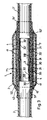
- Figure 1 shows two plastic tubes 2 and 2 ', which are connected to each other in the region of their ends 20 and 20'.
- the two tube ends 20 and 20 ' have circumferential grooves 21 and 21' which, for. B. run parallel to each other or the shape of a Can have thread.
- Both pipe ends 20 and 20 ⁇ are pushed onto the ends 30, 30 ⁇ of a metal inner sleeve 3.
- grooves 32 and 32 ⁇ are cut into each of these on the outside, into each of which a circumferential elastic sealing ring 33 and 33 ⁇ is inserted.
- the sealing rings 33 and 33 ⁇ are, as the drawing shows, preferably arranged in a region of the tube 2 or 2 ⁇ that is not weakened by the grooves 21 or 21 ⁇ in the outside of the tube ends 20 and 20 ⁇ . Between the ends of the tubes 2 and 2 ⁇ is a central flange 31 of the inner sleeve 3, which ensures that the insertion depths for the two tube ends 20 and 20 ⁇ are the same.
- an outer sleeve 4 is arranged around the pipe ends 20 and 20 ⁇ , leaving a space 42 open.
- the outer sleeve 4 is metallic here; however, it can also consist, for example, of a ceramic material or a plastic.
- the outer sleeve 4 has the shape of a hollow cylinder and has a multiplicity of evenly distributed openings 41.
- the outer part of the pipe connection 1 forms a formwork or casting mold 5, which is preferably in the form of two interconnectable, z. B. glued lockable half-shells is formed. It has tube openings 51 and 51 ⁇ at its front ends, the inside diameter of which corresponds to the outside diameter of the tubes 2 and 2 ⁇ . Furthermore, the casting mold 5 has in the region of the ends of the outer sleeve 4 in each case a step 52 or 52 ⁇ , by means of which the outer sleeve 4 is fixed in its position with respect to the tubes 2 and 2 ⁇ and the inner sleeve 3.
- the space 42 between the tube ends 20 and 20 ⁇ and the outer sleeve 4 and between the outer sleeve 4 and the mold 5 is initially with a jacket 55 flowable, then hardening mass filled.
- Such compositions are suitable, for example, two-component resins based on polyether-urethane or else thermoplastics.
- other suitable compositions are known to the person skilled in the art.
- To introduce the pourable mass into the interior of the casting mold 5, this has in its upper, middle part a filling opening 53 and in its upper part two ventilation openings 54 and 54 ⁇ offset relative to the filling opening 53 towards the end faces, in order to escape the inflowing one Potting compound to allow displaced air from inside the mold 5.
- the casting mold 5 is preferably made of a transparent plastic, e.g. B. polystyrene.
- the pipe connection shown in FIG. 1 is preferably produced according to the following procedure: First, the ends 20 and 20 ⁇ of the two plastic pipes 2 and 2 ⁇ to be connected to one another are provided with the grooves 21 and 21 ⁇ , which can be done, for example, with a thread cutter or another suitable tool. Then the outer sleeve 4 is pushed loosely over one of the pipes 2 and 2 und and first brought into a waiting position laterally offset from the pipe connection 1. Next, the sleeve ends 30 and 30 ⁇ of the inner sleeve 3 are inserted into the tube ends 20 and 20 ⁇ with the interposition of the sealing rings 33 and 33 ⁇ . Next, the outer sleeve 4 is shifted into its correct position, ie brought into the position shown in FIG. 1.
- the next step is to put on the casting mold 5, which, as mentioned, preferably consists of two half-shells.
- the outer sleeve 4 is fixed in position relative to the pipe ends 20 and 20 Rohr.
- the orientation of the casting mold 5 is of course to be chosen so that the filling opening 53 and the ventilation openings 54 and 54 ⁇ point upwards.
- the liquid, later hardening casting compound is then poured into the interior of the casting mold 5 through the filling opening 53 until all the voids and gaps in the interior of the casting mold 5 are completely filled with it.
- the pipe connection 1 is ready for use.
- the casting mold 5 remains as lost formwork on the pipe connection 1.
- FIG. 2 shows a pipe connection 1 ⁇ between a plastic pipe 2 and a metal T-piece 6.
- the end 20 of the plastic pipe 2 is provided on the outside with grooves 21, which here have a rectangular cross-sectional shape.
- a pipe seat 3 ' is inserted with the interposition of a sealing ring 33 inserted into a groove 32.
- the tube seat 3 ⁇ is made in one piece with the nozzle 60 of the T-piece 6.
- this also has grooves 34 on the outside, which here too have a rectangular cross-sectional shape.
- a metallic outer sleeve 4 is arranged, which in turn is designed with openings 41.
- the pipe connection 1 is closed by a suitably designed casting mold 5, which has a pipe opening 51 on its left end face, the inside diameter of which corresponds to the outside diameter of the plastic pipe 2, and which has a pipe opening 51 ⁇ on its right end side, the inside diameter of which corresponds to the outside diameter of the socket 60 of the T-piece 6 corresponds.
- the casting mold 5 again has steps 52 and 52 ⁇ for fixing the outer sleeve 4 relative to the pipe end 20 and the socket 60 of the T-piece 6.
- This space 42 and the space between the outer sleeve 4 and the mold 5 is again filled with the potting compound jacket 55.
- the casting compound in the exemplary embodiment according to FIG. 2 it has an upper-side filling opening 53 arranged in the area of the right front side and an upper-side ventilation opening 54 arranged near the left front side.
- the pipe connection 1 according to FIG. 2 is produced analogously to the pipe connection described in FIG. 1, but here the grooves 34 in the connection end 60 of the T-piece are expediently already introduced during its manufacture.
- the pipe seat 3 ⁇ can also be connected to the T-piece 6, e.g. B. to be screwed or soldered component.
- the pipe connection 1 can of course also be used for other constellations of pipes and / or other elements, in particular in installation technology, such as, for. B. for corner connections, branches, transitions from a pipe diameter to another diameter, for connections to valves or flow meters and the like.
- potting compounds are all material and temperature compatible materials, such as. B. concrete or ceramic masses, bitumens, metal casting compounds, hardening one- or multi-component resins or meltable plastics (thermoplastics), in particular polymers, insofar as they are initially in a flowing state and then in a solid or quasi-solid Overcome condition.
- FIG. 3 shows a further exemplary embodiment with a method variant in which, in contrast to the exemplary embodiment according to FIG. 1, no mold 55 is used.
- a thermoplastic at least partially outside the sleeve 4, e.g. melting polyethylene, a covering 7 of heat-shrinking film is pushed on, which envelops the thermoplastic composition 55 and the outer sleeve 4 as a whole and closes tightly at the ends. Otherwise, the configuration is the same as in FIG. 1.
- a temperature is generated in the connection area in which the thermoplastic is flowable and the film shrinks, so that the covering 7 exerts pressure on the mass 55 and this is the areas to be embedded.
- thermoplastic caused to flow, can for example be pushed on beforehand as a thermoplastic sleeve 75. Due to the shrinking sheath 7, a considerable pressure is exerted, which creates a tight, all-round jacket.
- the heating can take place, for example, using warm air blowers, high-frequency generators or immersion baths in heated liquids.
- Such a shrinkable covering 7 can also be used to inject a flowable mass which is not a thermoplastic, but which, according to its composition, maintains its flowable consistency for a certain time and can be pressed into the areas to be embedded during the time of its flowability analogously to the processes described .
Landscapes
- Engineering & Computer Science (AREA)
- Mechanical Engineering (AREA)
- General Engineering & Computer Science (AREA)
- Chemical & Material Sciences (AREA)
- Composite Materials (AREA)
- Lining Or Joining Of Plastics Or The Like (AREA)
- Mutual Connection Of Rods And Tubes (AREA)
- Laying Of Electric Cables Or Lines Outside (AREA)
- Exchange Systems With Centralized Control (AREA)
- Mechanical Coupling Of Light Guides (AREA)
- Joints With Sleeves (AREA)
Description
- Die Erfindung betrifft ein Verfahren zum Verbinden von zwei Rohrenden oder von mit Stutzen versehenen Formstücken mit einem Rohrende. Die beiden Rohrenden werden dabei auf die beiden Enden einer dicht anliegenden Innenhülse oder das mit dem Stutzen zu verbindende Rohrende auf einen Rohrsitz des Stutzen aufgeschoben und anschließend mit außen den aufgeschobenen Bereich umspannenden Mitteln festgelegt, entsprechend dem Merkmal b) des Anspruches 1.
- Derartige Verbindungen können angewandt werden auf Kunststoff-, Metall- oder Keramikrohre. Unter mit Stutzen versehen Formstücken werden beispielsweise aus der Instalationstechnik bekannte T-Stücke, Übergangsstücke, Verteiler, Ventile und dergleichen verstanden. Insbesondere eignet sich das Verbindungsverfahren und die Verbindung für im Bereich der Brauchwasserinstallation zu verwendende Kunststoffrohre aus vernetztem Polyethylen (VPE). In der Installationstechnik verwendet man im allgemeinen Verbindungen, die aus einem Einsatzstück, das in das Ende eines Kunststoffrohres eingesteckt wird, aus einem im Querschnitt keilförmigen, längsgeschlitzten Klemmring, der außen auf das Rohrende aufgesetzt wird und aus einer mit dem Einsatzstück zu verschraubenden, den Klemmring überdeckenden und unter Zwischenlage des Rohrendes gegen das Einsatzstück verspannenden Überwurfmutter bestehen. Die einzelnen Teile sind aufwendig in der Herstellung und damit teuer, insbesondere bei größeren Rohrdimensionen. Ein anderer Nachteil ist, daß die Verschraubung, je nachdem, wer sie ausführt, mehr oder weniger fest angezogen wird, was zu starken Streuungen in der Qualität der Rohrverbindung führt. Als weiterer Nachteil ist noch anzuführen, daß Kunststoffrohre dazu neigen, unter Preßdruck zu fließen, so daß mit der Zeit der Verschraubungsdruck auf das Rohr nachläßt. Diese sogenannte Relaxation führt zu Undichtigkeiten der Rohrverbindung und erfordert zu deren Vermeidung eine ständige Kontrolle und ein Nachziehen der Verschraubung.
- Es ist weiterhin bekannt ein Verfahren der eingangs genannten Art (vgl. FR-A-2 113 512), bei dam um die Rohrenden, die auf die Innenhülse geschoben sind, eine verflüssigbare Masse aus Kunststoff außen angebracht wird. Anschließend wird eine steife Außenhülse über die Rohrenden geschoben, wobei dann der Zwischenraum zwischen Innenmantel der Außenhülse und Außenseite der Rohrenden mit der genannten elastischen Dichtungs- oder Klebemasse gefüllt ist.
- Als nachteilig wird hierbei empfungen, daß die Dichtungsmasse zu der Steifigkeit der Verbindung nicht beiträgt, sondern lediglich eine dünne Dicht- oder Klebeschicht bildet.
- Es stellt sich daher die Aufgabe, eine Verbindung der eingangs genannten Art zu schaffen, bei der auch die Dichtungsschicht zwischen Außenhülse und Innenmantel zur Steifigkeit der Verbindung wesentlich beiträgt, die kostengünstig ausführbar ist, einfach und mit gleichbleibender Qualität herstellbar ist und die eine hohe Langzeitstabilität und -dichtigkeit gewährleistet.
- Die Lösung dieser Aufgabe gelingt erfindungsgemäß durch ein Verfahren gemäß dem kennzeichnenden Teil des Anspruches 1.
- Als Vergußmassen eignen sich alle material- und temperaturverträglichen Materialien, wie z. B. betonartige oder keramische Massen, Bitumina, metallene Vergußmassen mit niedrigen Schmelzpunkten, aushärtende Ein- bzw. Mehr-Komponenten-Harze, Elastomere, Duromere oder schmelzfähige Kunststoffe (Thermoplaste), insbesondere Polymerisate, soweit sie zunächst in einem fließenden Zustand sich befinden oder gebracht werden und anschließend in einen festen oder quasi festen Zustand übergehen.
- Von besonderem Vorteil ist eine an sich aus der FR-A-2 113 512 bekannte Verfahrensvariante, bei der um die Außenhülse und der wenigstens teilweise außerhalb der Hülse befindlichen Masse, z. B. einem Thermoplasten, eine Umhüllung aus wärmeschrumpfender Folie aufgeschoben wird, anschließend der Verbindungsbereich auf eine, Temperatur erhitzt wird, bei der der gegebenenfalls verwendete Thermoplast fließfähig ist und die Folie schrumpft, wobei die Umhüllung Druck auf die fließende Masse ausübt und diese in die einzubettenden Bereiche drückt.
- In Abwandlung dazu kann auch mit einer Gießform gearbeitet werden, in die die Masse eingegossen wird.
- Vorzugsweise werden das Kunststoffrohr und gegebenenfalls das (Installations-)Element an seinem Verbindungsende außenseitig haftreibungserhöhend, z. B. mit im wesentlichen in Umfangsrichtung verlaufenden Rillen oder Stegen, vorstehenden Zähnen, aufgepreßten Zahnringen oder dergleichen, strukturiert und in das Rohrende eine hohlzylindrische Innenhülse dichtend eingesetzt. Anstelle einer mechanischen Strukturierung kann auch eine chemotechnische Strukturierung treten, z. B. durch angelöste Oberflächenbereiche, wobei dies auch beispielsweise durch ein der Vergußmasse beigefügtes Lösungsmittel geschehen kann.
- Von Vorteil ist, daß bei der erhaltenen Rohrverbindung kein Druck auf das Kunststoffrohr ausgeübt wird, so daß es nicht zu einem Fließen des Kunststoffes kommen kann. In Längsrichtung der Verbindung wirkende Kräfte werden von der mit den strukturierten Oberflächen von Rohrende und Außenhülse verzahnten Vergußmasse aufgefangen. Die Außenhülse sorgt zudem für eine sichere Aufnahme von nach außen wirkenden Kräften. Die bei thermischen Wechselbelastungen auftretenden Dehnungen und Verkürzungen werden von der Vergußmasse elastisch aufgefangen. Damit bietet die neue Verbindung ein hohes Maß an Sicherheit hinsichtlich Dichtigkeit und Stabilität über einen langen Zeitraum auch bei hohen Druck- und Temperaturbelastungen.
- Vorteilhafte Ausgestaltungen der Erfindung sind in den Unteransprüchen angegeben.
- Die Erfindung wird im folgenden anhand einer Zeichnung erläutert. Die Figuren der Zeichnung zeigen:
- Figur 1
- eine Rohrverbindung zwischen zwei Kunststoffrohren,
- Figur 2
- eine Rohrverbindung zwischen einem Kunststoffrohr und einem Metall-T-Stück und
- Figur 3
- eine Rohrverbindung gemäß Figur 1, die mit einem Schlauch aus Schrumpffolie durchgeführt wird.
- Figur 1 zeigt zwei Kunststoffrohre 2 und 2', die im Bereich ihrer Enden 20 und 20' miteinander verbunden sind. Außenseitig weisen die beiden Rohrenden 20 und 20' in Umfangsrichtung verlaufende Rillen 21 bzw. 21' auf, die z. B. parallel zueinander verlaufen oder die Form eines Gewindes haben können. Beide Rohrenden 20 bzw. 20ʹ sind auf die Enden 30, 30ʹ einer metallenen Innenhülse 3 aufgeschoben. Im Bereich der Enden 30 und 30ʹ sind in diese jeweils außenseitige Nuten 32 bzw. 32ʹ eingeschnitten, in welche jeweils ein umlaufender elastischer Dichtring 33 bzw. 33ʹ eingelegt ist. Die Dichtringe 33 und 33ʹ sind dabei, wie die Zeichnung zeigt, vorzugsweise in einem Bereich des Rohres 2 bzw. 2ʹ angeordnet, der nicht durch die Rillen 21 bzw. 21ʹ in der Außenseite der Rohrenden 20 und 20ʹ geschwächt ist. Zwischen den Stirnenden der Rohre 2 und 2ʹ liegt ein Mittelflansch 31 der Innenhülse 3, der dafür sorgt, daß die Einstecktiefen für die beiden Rohrenden 20 und 20ʹ gleich sind.
- In Richtung nach außen folgend ist um die Rohrenden 20 und 20ʹ herum unter Freilassung eines Zwischenraumes 42 eine Außenhülse 4 angeordnet. Die Außenhülse 4 ist hier metallisch ausgeführt; sie kann jedoch auch beispielsweise aus einem keramischen Material oder aus einem Kunststoff bestehen. Die Außenhülse 4 hat die Form eines Hohlzylinders und weist eine Vielzahl von gleichmäßig verteilten Durchbrechungen 41 auf.
- Den äußeren Teil der Rohrverbindung 1 bildet eine Schalung oder Gießform 5, die vorzugsweise in Form zweier miteinander verbindbarer, z. B. verklebbarer verrastbarer Halbschalen ausgebildet ist. Sie weist an ihren stirnseitigen Enden Rohröffnungen 51 und 51ʹ auf, deren Innendurchmesser dem Außendurchmesser der Rohre 2 und 2ʹ entspricht. Weiterhin besitzt die Gießform 5 im Bereich der Enden der Außenhülse 4 jeweils eine Stufung 52 bzw. 52ʹ, mittels welcher die Außenhülse 4 in ihrer Lage zu den Rohren 2 und 2ʹ sowie der Innenhülse 3 fixiert wird.
- Der Zwischenraum 42 zwischen den Rohrenden 20 bzw. 20ʹ und der Außenhülse 4 sowie zwischen der Außenhülse 4 und der Gießform 5 ist mit einem Mantel 55 aus einer zunächst fließfähigen, anschließend erhärtenden Masse ausgefüllt. Als derartige Massen eignen sich beispielsweise Zwei-Komponenten-Harze auf Polyether-Urethan-Basis oder aber auch Thermoplasten. Darüberhinaus sind dem Fachmann weitere geeignete Massen bekannt. Zur Einbringung der vergießfähigen Masse in das Innere der Gießform 5 weist diese in ihrem oberen, mittleren Teil eine Einfüllöffnung 53 und in ihrem oberen Teil zwei gegenüber der Einfüllöffnung 53 zu den Stirnseiten hin versetzte Entlüftungsöffnungen 54 und 54ʹ auf, um ein Entweichen der von der einströmenden Vergußmasse Verdrängten Luft aus dem Inneren der Vergießform 5 zu ermöglichen. Zur genauen Kontrolle des Gießvorganges besteht die Gießform 5 vorzugsweise aus einem durchsichtigen Kunststoff, z. B. Polystyrol.
- Die Herstellung der in Figur 1 gezeigten Rohrverbindung erfolgt vorzugsweise nach folgendem Verfahrensablauf:
Zunächst werden die Enden 20 und 20ʹ der beiden miteinander zu verbindenden Kunststoffrohre 2 und 2ʹ mit den Rillen 21 bzw. 21ʹ versehen, was beispielsweise mit einem Gewindeschneider oder einem anderen geeigneten Werkzeug erfolgen kann. Anschließend wird die Außenhülse 4 lose über eines der Rohre 2 und 2ʹ geschoben und zunächst in eine gegenüber der Rohrverbindung 1 seitlich versetzte Warteposition gebracht. Als nächstes werden die Hülsenenden 30 und 30ʹ der Innenhülse 3 in die Rohrenden 20 und 20ʹ unter Zwischenlage der Dichtringe 33 und 33ʹ eingesteckt. Als nächstes wird die Außenhülse 4 in ihre richtige Position verschoben, d. h. in die in der Figur 1 dargestellte Lage gebracht. Der nächste Schritt ist das Anlegen der Gießform 5, die, wie erwähnt, vorzugsweise aus zwei Halbschalen besteht. Durch das Anlegen der Gießform 5 wird zugleich die Außenhülse 4 in ihrer Lage relativ zu den Rohrenden 20 und 20ʹ fixiert. Die orientierung der Gießform 5 ist dabei selbstverständlich so zu wählen, daß die Einfüllöffnung 53 und die Entlüftungsöffnungen 54 und 54ʹ nach oben weisen. Anschliessend wird durch die Einfüllöffnung 53 die flüssige, später aushärtende Vergußmasse in das Innere der Gießform 5 eingefüllt, bis alle Hohl- und Zwischenräume im Inneren der Gießform 5 vollständig damit gefüllt sind. Nach dem Erhärten der Vergußmasse ist die Rohrverbindung 1 einsatzfertig. Die Gießform 5 verbleibt als verlorene Schalung an der Rohrverbindung 1. - Figur 2 zeigt eine Rohrverbindung 1ʹ zwischen einem Kunststoffrohr 2 und einem metallenen T-Stück 6. Auch bei diesem Ausführungsbeispiel der Rohrverbindung ist das Ende 20 des Kunststoffrohres 2 außenseitig mit Rillen 21 versehen, die hier eine rechteckige Querschnittsform aufweisen. An das Rohrende 20 ist unter Zwischenlage eines in eine Nut 32 eingelegten Dichtringes 33 ein Rohrsitz 3ʹ eingeschoben. Der Rohrsitz 3ʹ ist mit dem Stutzen 60 des T-Stücks 6 einstückig ausgeführt. Im Bereich des Stutzens 60 des T-Stückes 6 weist dieses außenseitig ebenfalls Rillen 34 auf, die auch hier eine rechteckige Querschnittsform haben. Um das Rohrende 20 und die Teile 60 und 3ʹ des T-Stückes 6 herum ist eine metallische Außenhülse 4 angeordnet, die hier wiederum mit Durchbrechungen 41 ausgeführt ist.
- Nach außen wird die Rohrverbindung 1 abgeschlossen durch eine passend ausgebildete Gießform 5, die an ihrer linken Stirnseite eine Rohröffnung 51 aufweist, deren Innendurchmesser dem Außendurchmesser des Kunststoffrohres 2 entspricht und die an ihrer rechten Stirnseite eine Rohröffnung 51ʹ aufweist, deren Innendurchmesser dem Außendurchmesser des Stutzens 60 des T-Stückes 6 entspricht. Weiterhin besitzt die Gießform 5 auch hier wieder Stufungen 52 bzw. 52ʹ für die Fixierung der Außenhülse 4 relativ zu dem Rohrende 20 und dem Stutzen 60 des T-Stückes 6. Auch hier ist wieder ein Zwischenraum 42 zwischen dem Rohrende 20 und dem Stutzen 60 des T-Stückes 6 sowie der Außenhülse 4 vorhanden, der in der Praxis vorzugsweise einige Millimeter weit ist. Dieser Zwischenraum 42 sowie der Raum zwischen der Außenhülse 4 und der Gießform 5 ist wieder mit dem Vergußmasse-Mantel 55 ausgefüllt. Zur Einbringung der Vergußmasse in die Gießform 5 weist diese beim Ausführungsbeispiel nach Figur 2 eine im Bereich der rechten Stirnseite angeordnete oberseitige Einfüllöffnung 53 sowie eine in der Nähe der linken Stirnseite angeordnete oberseitige Entlüftungsöffnung 54 auf.
- Die Herstellung der Rohrverbindung 1 gemäß Figur 2 erfolgt analog zu der unter Figur 1 beschriebenen Rohrverbindung, wobei hier allerdings die Rillen 34 in dem Verbindungsende 60 des T-Stückes zweckmäßig bereits bei dessen Herstellung eingebracht sind. In Abwandlung der Rohrverbindung 1 nach Figur 2 kann der Rohrsitz 3ʹ auch als mit dem T-Stück 6 zu verbindendes, z. B. zu verschraubendes oder zu verlötendes Bauteil ausgeführt sein.
- Außer den beschriebenen Ausführungsbeispielen kann die Rohrverbindung 1 selbstverständlich auch für andere Konstellationen von Rohren und/oder anderen Elementen, insbesondere in der Installationstechnik verwendet werden, wie z. B. für Eckverbindungen, Abzweigungen, Übergänge von einem Rohrdurchmesser zu einem anderen Durchmesser, für Anschlüsse an Ventile oder Durchflußmesser und dergleichen mehr.
- Als Vergußmassen eignen sich alle material- und temperaturverträglichen Materialien, wie z. B. betonartige oder keramische Massen, Bitumina, metallene Vergußmassen, aushärtende Ein- bzw. Mehr-Komponenten-Harze oder schmelzfähige Kunststoffe (Thermoplaste), insbesondere Polymerisate, soweit sie zunächst in einem fließenden Zustand sich befinden und anschließend in einen festen oder quasi-festen Zustand übergehen.
- Figur 3 zeigt ein weiteres Ausführungsbeispiel mit einer Verfahrensvariante, bei der im Gegensatz zum Ausführungsbeispiel gemäß Figur 1 keine Gießform 55 verwendet wird. Um die Außenhülse 4 und einem wenigstens teilweise außerhalb der Hülse 4 befindlichen Thermoplasten, z.B. schmelzendes Polyethylen, ist eine Umhüllung 7 aus wärmeschrumpfender Folie aufgeschoben, die die thermoplastische Masse 55 und die Außenhülse 4 insgesamt einhüllt und an den Enden fest abschließt. Im übrigen handelt es sich um dieselbe Konfiguration wie in Figur 1. Zur Herstellung der Verbindung wird im Verbindungsbereich eine Temperatur erzeugt, in der der Thermoplast fließfähig ist und die Folie schrumpft, so daß die Umhüllung 7 einen Druck auf die Masse 55 ausübt und diesein die einzubettenden Bereiche hineindrückt. Die thermoplastische, zum Fließen gebrachte Masse, kann beispielsweise als eine thermoplastische Hülse 75 vorher aufgeschoben werden. Durch die schrumpfende Umhüllung 7 wird ein erheblicher Druck ausgeübt, der einen dichten, allseits anliegenden Mantel entstehen läßt. Das Erwärmen kann beispielsweise durch Warmluftgebläse, Hochfrequenz-Generatoren oder durch Tauchbäder in erwärmten Flüssigkeiten geschehen.
- Eine solche schrumpffähige Umhüllung 7 kann auch zum Einpressen einer fließfähigen Masse verwendet werden, die kein Thermoplast ist, sondern entsprechend ihrer Zusammensetzung für eine bestimmte Zeit ihre fließfähige Konsistenz bewahrt und sich während der Zeit ihrer Fließfähigkeit analog zu den beschriebenen Vorgängen in die einzubettenden Bereiche drücken läßt.
Claims (10)
- Verfahren zum Verbinden von zwei Rohrenden (20, 20') oder von mit Stutzen (60) versehenen Formstücken mit einem Rohrende (20), mit folgenden Verfahrensschritten:a) die beiden Rohrenden (20, 20') werden auf die beiden Enden einer dicht anliegenden Innenhülse (3) oder auf das mit dem Stutzen (60) zu verbindende Rohrende (20) auf einen Rohrsitz (3') des Stutzens (60) aufgeschoben;b) um die Rohrenden (20, 20') bzw. um das Rohrende (20) und den Stutzen (60) mit Rohrsitz (3') wird eine steife Außenhülse (4) gelegt, wobei ein vorhandener Zwischenraum (42) zwischen Innenmantel der Außenhülse (4) und Außenseite der Rohrenden mit einer verflüssigbaren Masse ausgefüllt wird,
dadurch gekennzeichnet, daß die verflüssigbare Masse in den innerhalb der Außenhülse (4) befindlichen Raum eingedrückt oder eingegossen wird und anschließend erhärtet, so daß anschließend die Rohrenden (20, 20') bzw. das Rohrende (20) oder Stutzen (60) mit Rohrsitz (3') sowie mindestens die Innenseiten der Außenhülse (4) in einem Rohrende(n) (20, 20'), gegebenenfalls mit Stutzen (60), übergreifenden Mantel (55) aus der erhärteten Masse eingebettet und gehalten sind. - Verfahren nach Anspruch 1, dadurch gekennzeichnet, daß die Außenhülse (4) mit einer Vielzahl von Durchbrechungen (41) versehen ist.
- Verfahren nach Anspruch 1, dadurch gekennzeichnet, daß als Masse Elastomere, Thermoplaste Duromere oder Metalle mit niedrigem Schmelzpunkt verwendet werden.
- Verfahren nach wenigstens einem der Ansprüche 1 bis 3, dadurch gekennzeichnet, daß um die Außenhülse (4) und um die wenigstens teilweise außerhalb der Außenhülse (4) befindlichen Masse, aus einem Thermoplasten, eine Umhüllung (7) aus wärmeschrumpfenden Material aufgeschoben wird, anschließend der Verbindungsbereich auf eine Temperatur erhitzt wird, in der bei Verwendung desselben der Thermoplast fließfähig wird und die Folie der Umhüllung (7) schrumpft, wobei dabei die Umhüllung (7) Druck auf die fließfähige vorhandene Masse ausübt und diese in die einzubettenden Bereiche drückt.
- Verfahren nach Anspruch 1 bis 3, dadurch gekennzeichnet, daß eine der Enden (20, 20'; 60) sowie die Außenhülse (4) umgebende und in ihrer Lage zueinander fixierende, als verlorene Schalung dienende, die Vergußmasse aufnehmende Gießform (5) verwendet wird, die vorzugsweise aus zwei Formhälften zusammensetzbar ist und die mindestens eine Einfüllöffnung (53) für die Vergußmasse aufweist.
- Verfahren nach Anspruch 5, dadurch gekennzeichnet, daß die Gießform (5) aus Kunststoff, vorzugsweise aus durchsichtigem Polystyrol besteht.
- Verfahren nach den Ansprüchen 5 und 6, dadurch gekennzeichnet, daß an die Gießform (5) stirnseitig Ansatzstücke mit Rohröffnungen unterschiedlichen Durchmessers wahlweise ansetzbar sind.
- Verfahren nach Anspruch 1, dadurch gekennzeichnet, daß jeweils die Rohrenden (20; 20'), gegebenenfalls der Stutzen (60) außerhalb des Rohrsitzes (3'), außenseitig haftreibungserhöhend, z.B. mit im wesentlichen in Umfangsrichtung verlaufenden Rillen (21, 21', 34) oder Stegen, vorstehenden Zähnen, aufgepreßten Zahnringen oder dergleichen, strukturiert oder mit einer angelösten Oberfläche versehen werden.
- Verfahren nach Anspruch 8, dadurch gekennzeichnet, daß die Außenhülse (4) zumindest innenseitig haftreibungserhöhend strukturiert wird.
- Verfahren nach Anspruch 8, dadurch gekennzeichnet, daß wenigstens ein elastischer Dichtring (33, 33'), vorzugsweise ein in eine Nut (32, 32') eingelegter O-Ring, zwischen Innenhülse (3) und Rohrende (20; 20') angeordnet wird.
Priority Applications (1)
| Application Number | Priority Date | Filing Date | Title |
|---|---|---|---|
| AT87114772T ATE71199T1 (de) | 1987-09-05 | 1987-10-09 | Verbindungssystem. |
Applications Claiming Priority (2)
| Application Number | Priority Date | Filing Date | Title |
|---|---|---|---|
| EP87113016 | 1987-09-05 | ||
| EP87113016 | 1987-09-05 |
Publications (2)
| Publication Number | Publication Date |
|---|---|
| EP0306554A1 EP0306554A1 (de) | 1989-03-15 |
| EP0306554B1 true EP0306554B1 (de) | 1992-01-02 |
Family
ID=8197263
Family Applications (1)
| Application Number | Title | Priority Date | Filing Date |
|---|---|---|---|
| EP87114772A Expired - Lifetime EP0306554B1 (de) | 1987-09-05 | 1987-10-09 | Verbindungssystem |
Country Status (3)
| Country | Link |
|---|---|
| EP (1) | EP0306554B1 (de) |
| AT (1) | ATE71199T1 (de) |
| DE (1) | DE3775772D1 (de) |
Families Citing this family (6)
| Publication number | Priority date | Publication date | Assignee | Title |
|---|---|---|---|---|
| DE59008994D1 (de) * | 1989-03-31 | 1995-06-08 | Geberit Ag | Schweissmuffe. |
| FI895439A7 (fi) * | 1989-11-15 | 1991-05-16 | Neste Oy | Foerfarande foer framstaellning av en fog och fog mellan delar som ska anslutas till varandra och omges av foerbindningsaemne samt form foer framstaellning av en fog. |
| CH683121A5 (de) * | 1990-07-05 | 1994-01-14 | Geberit Ag | Elektrisch heizbare Schweissmuffe. |
| FI87319C (fi) * | 1991-12-20 | 1992-12-28 | Neste Oy | Foerfarande foer limning av korsverkkonstruktioner av plastprofil och limfoerbindning foer korsverkkonstruktioner som framstaellts plastprofil |
| DE19625359A1 (de) * | 1996-06-25 | 1998-01-02 | Sachsenring Automobiltechnik G | Verfahren zur Herstellung eines Verbindungsknotens |
| CN114427625A (zh) * | 2020-10-29 | 2022-05-03 | 中国石油化工股份有限公司 | 一种油田用rtp管及其连接方式 |
Family Cites Families (4)
| Publication number | Priority date | Publication date | Assignee | Title |
|---|---|---|---|---|
| US3415287A (en) * | 1964-08-21 | 1968-12-10 | Raychem Corp | Protective covering and article |
| US3561795A (en) * | 1968-04-15 | 1971-02-09 | Montagewerk Leipzig Veb | Pipe connections |
| GB1373100A (en) * | 1970-11-03 | 1974-11-06 | Raychem Ltd | Heat-recoverable members |
| JPS60232932A (ja) * | 1984-04-04 | 1985-11-19 | レイケム・コーポレイシヨン | 熱回復性物品 |
-
1987
- 1987-10-09 EP EP87114772A patent/EP0306554B1/de not_active Expired - Lifetime
- 1987-10-09 DE DE8787114772T patent/DE3775772D1/de not_active Expired - Lifetime
- 1987-10-09 AT AT87114772T patent/ATE71199T1/de active
Also Published As
| Publication number | Publication date |
|---|---|
| ATE71199T1 (de) | 1992-01-15 |
| DE3775772D1 (de) | 1992-02-13 |
| EP0306554A1 (de) | 1989-03-15 |
Similar Documents
| Publication | Publication Date | Title |
|---|---|---|
| DE69006289T2 (de) | Verfahren zur Verhinderung von Wasserleckage in Rohrleitungen und Rohrinnenbeschichtung zur Verhinderung von Wasserleckage. | |
| DE3721577C2 (de) | ||
| DE3414180A1 (de) | Dichtungseinrichtung fuer aneinanderstossende, zumindest etwa rohrfoermige bauteile, insbesondere fuer betonformteile | |
| EP1218657A1 (de) | Rohrförmiges kupplungsteil zur herstellung einer klebeverbindung mit einer fluidleitung | |
| DE3533000A1 (de) | Muffenrohrverbindung fuer kunststoffrohre | |
| EP3574167A1 (de) | Abdichtung einer durchführung eines ankerstabs durch ein rahmenschalelement | |
| DE1925171A1 (de) | Verbindungsvorrichtung oder Kupplung | |
| EP0306554A1 (de) | Verbindungssystem | |
| EP0102919A2 (de) | Verfahren zum Verbinden von Rohren und danach hergestellte Rohrverbindung | |
| DE8320655U1 (de) | Gewinderohrmuffe | |
| DE102015120268A1 (de) | Rohrsanierungsverfahren | |
| DE3534174A1 (de) | Krumpfmuffe aus kunststoff zum verbinden von zwei rohrenden | |
| CH715401A2 (de) | Vorrichtung zur Verhinderung der Schallübertragung durch einen Durchbruch oder einen fertigungstechnisch bedingten Kanal in einer Wand und ein Verfahren zum schalldichten Verschliessen eines Durchbruchs oder eines fertigungstechnisch bedingten Kanals in einer Wand. | |
| AT397845B (de) | Verbindungsstück zum anschluss einer metallischen armatur an ein kunststoff-leitungsrohr für flüssige medien | |
| DE102018109998A1 (de) | Rohranschlusssystem und Verfahren zur Herstellung eines Rohranschlusses | |
| DE2600621C3 (de) | Gewindelose Verbindung für Rohre und Verfahren zu ihrer Herstellung | |
| DE3021346C2 (de) | ||
| DE2327159B2 (de) | Einfach- und doppelsteckmuffe zur verbindung von rohrenden und formstuecken bei im wickelverfahren hergestellten faserverstaerkten kunststoffrohren | |
| DE4442407C1 (de) | Muffe mit werksseitig eingefülltem Dichtmittel | |
| DE69613576T2 (de) | Quetschverbindung für rohre | |
| DE69100542T2 (de) | Muffenrohr aus Kunststoff sowie Herstellungsverfahren dafür. | |
| DE3616535C2 (de) | Kabelmuffe aus einem Muffenrohr und aus zwei seitlich sich anschließenden, schrumpfbaren Muffenköpfen | |
| DE3524282C1 (de) | Dichtung für Stoßstellen von Rohren, insbesondere Betonfertigrohren | |
| DE2949165C2 (de) | Dichtungssystem mit Dichtungseinlagen für Kabelgarnituren | |
| DE3323379A1 (de) | Uebergangsstueck in einer gasleitung |
Legal Events
| Date | Code | Title | Description |
|---|---|---|---|
| PUAI | Public reference made under article 153(3) epc to a published international application that has entered the european phase |
Free format text: ORIGINAL CODE: 0009012 |
|
| AK | Designated contracting states |
Kind code of ref document: A1 Designated state(s): AT BE CH DE ES FR GB GR IT LI LU NL SE |
|
| 17P | Request for examination filed |
Effective date: 19890518 |
|
| 17Q | First examination report despatched |
Effective date: 19900710 |
|
| RAP1 | Party data changed (applicant data changed or rights of an application transferred) |
Owner name: HEWING GMBH |
|
| GRAA | (expected) grant |
Free format text: ORIGINAL CODE: 0009210 |
|
| AK | Designated contracting states |
Kind code of ref document: B1 Designated state(s): AT BE CH DE ES FR GB GR IT LI LU NL SE |
|
| PG25 | Lapsed in a contracting state [announced via postgrant information from national office to epo] |
Ref country code: SE Effective date: 19920102 Ref country code: GB Effective date: 19920102 Ref country code: IT Free format text: LAPSE BECAUSE OF FAILURE TO SUBMIT A TRANSLATION OF THE DESCRIPTION OR TO PAY THE FEE WITHIN THE PRE;WARNING: LAPSES OF ITALIAN PATENTS WITH EFFECTIVE DATE BEFORE 2007 MAY HAVE OCCURRED AT ANY TIME BEFORE 2007. THE CORRECT EFFECTIVE DATE MAY BE DIFFERENT FROM THE ONE RECORDED.SCRIBED TIME-LIMIT Effective date: 19920102 Ref country code: FR Effective date: 19920102 Ref country code: BE Effective date: 19920102 Ref country code: GR Free format text: LAPSE BECAUSE OF FAILURE TO SUBMIT A TRANSLATION OF THE DESCRIPTION OR TO PAY THE FEE WITHIN THE PRESCRIBED TIME-LIMIT Effective date: 19920102 Ref country code: NL Effective date: 19920102 |
|
| REF | Corresponds to: |
Ref document number: 71199 Country of ref document: AT Date of ref document: 19920115 Kind code of ref document: T |
|
| REF | Corresponds to: |
Ref document number: 3775772 Country of ref document: DE Date of ref document: 19920213 |
|
| PG25 | Lapsed in a contracting state [announced via postgrant information from national office to epo] |
Ref country code: ES Free format text: LAPSE BECAUSE OF FAILURE TO SUBMIT A TRANSLATION OF THE DESCRIPTION OR TO PAY THE FEE WITHIN THE PRESCRIBED TIME-LIMIT Effective date: 19920413 |
|
| EN | Fr: translation not filed | ||
| NLV1 | Nl: lapsed or annulled due to failure to fulfill the requirements of art. 29p and 29m of the patents act | ||
| GBV | Gb: ep patent (uk) treated as always having been void in accordance with gb section 77(7)/1977 [no translation filed] | ||
| PG25 | Lapsed in a contracting state [announced via postgrant information from national office to epo] |
Ref country code: AT Effective date: 19921009 |
|
| PG25 | Lapsed in a contracting state [announced via postgrant information from national office to epo] |
Ref country code: LU Free format text: LAPSE BECAUSE OF NON-PAYMENT OF DUE FEES Effective date: 19921031 Ref country code: LI Effective date: 19921031 Ref country code: CH Effective date: 19921031 |
|
| PLBE | No opposition filed within time limit |
Free format text: ORIGINAL CODE: 0009261 |
|
| STAA | Information on the status of an ep patent application or granted ep patent |
Free format text: STATUS: NO OPPOSITION FILED WITHIN TIME LIMIT |
|
| 26N | No opposition filed | ||
| REG | Reference to a national code |
Ref country code: CH Ref legal event code: PL |
|
| PGFP | Annual fee paid to national office [announced via postgrant information from national office to epo] |
Ref country code: DE Payment date: 19951207 Year of fee payment: 9 |
|
| PG25 | Lapsed in a contracting state [announced via postgrant information from national office to epo] |
Ref country code: DE Effective date: 19970701 |