EP0306220A2 - Manipulateur pour le transfert de rayonnement laser dans une fibre optique - Google Patents
Manipulateur pour le transfert de rayonnement laser dans une fibre optique Download PDFInfo
- Publication number
- EP0306220A2 EP0306220A2 EP88307890A EP88307890A EP0306220A2 EP 0306220 A2 EP0306220 A2 EP 0306220A2 EP 88307890 A EP88307890 A EP 88307890A EP 88307890 A EP88307890 A EP 88307890A EP 0306220 A2 EP0306220 A2 EP 0306220A2
- Authority
- EP
- European Patent Office
- Prior art keywords
- axis
- fibre
- manipulator device
- optical
- supporting tube
- Prior art date
- Legal status (The legal status is an assumption and is not a legal conclusion. Google has not performed a legal analysis and makes no representation as to the accuracy of the status listed.)
- Granted
Links
- 239000013307 optical fiber Substances 0.000 title claims abstract description 18
- 239000000835 fiber Substances 0.000 claims abstract description 38
- 230000003287 optical effect Effects 0.000 claims abstract description 15
- 239000011521 glass Substances 0.000 claims description 23
- XEEYBQQBJWHFJM-UHFFFAOYSA-N Iron Chemical compound [Fe] XEEYBQQBJWHFJM-UHFFFAOYSA-N 0.000 claims description 6
- 239000005304 optical glass Substances 0.000 claims description 5
- 230000005291 magnetic effect Effects 0.000 claims description 4
- 229910052742 iron Inorganic materials 0.000 claims description 3
- 238000009966 trimming Methods 0.000 description 9
- 230000010287 polarization Effects 0.000 description 7
- 230000000694 effects Effects 0.000 description 4
- 230000008878 coupling Effects 0.000 description 3
- 238000010168 coupling process Methods 0.000 description 3
- 238000005859 coupling reaction Methods 0.000 description 3
- 238000010586 diagram Methods 0.000 description 2
- 241000937413 Axia Species 0.000 description 1
- 238000010276 construction Methods 0.000 description 1
- 238000006073 displacement reaction Methods 0.000 description 1
- 239000000428 dust Substances 0.000 description 1
- 239000013536 elastomeric material Substances 0.000 description 1
- 239000000696 magnetic material Substances 0.000 description 1
- 239000002184 metal Substances 0.000 description 1
- 229910052751 metal Inorganic materials 0.000 description 1
Images
Classifications
-
- G—PHYSICS
- G02—OPTICS
- G02B—OPTICAL ELEMENTS, SYSTEMS OR APPARATUS
- G02B6/00—Light guides; Structural details of arrangements comprising light guides and other optical elements, e.g. couplings
- G02B6/24—Coupling light guides
- G02B6/42—Coupling light guides with opto-electronic elements
- G02B6/4201—Packages, e.g. shape, construction, internal or external details
- G02B6/4219—Mechanical fixtures for holding or positioning the elements relative to each other in the couplings; Alignment methods for the elements, e.g. measuring or observing methods especially used therefor
- G02B6/422—Active alignment, i.e. moving the elements in response to the detected degree of coupling or position of the elements
- G02B6/4226—Positioning means for moving the elements into alignment, e.g. alignment screws, deformation of the mount
Definitions
- the invention relates to a manipulator device for the transfer of laser light into an optical fibre and of the type comprising - supporting means for an optical fibre, - means for adjusting the position of the end face of the optical fibre in the axial direction (z-axis) of the fibre corresponding to the optical axis of the manipulator and in relation to a focused laser beam, - an optical system for the focusing of a laser beam arriving substantially axially at an end face of the optical fibre, - means for adjusting the spot of light provided by the focused laser beam on the end face of the fibre in two axial x- and y-directions perpendicular to each other and to said z-axis, and means for angularly adjusting the axial direction of the fibre in relation to the axial direction of the laser beam incident on the end face of the fibre.
- the interspace between the objective and the end face of the fibre, ie. the focusing zone in the prior manipulator is freely accessible so that said known structure does not take additional parameters into account that may influence the passing efficiency, viz. temperature and vibration stability, humidity and dust on the objective and the end face of the fibre, and so on.
- the transferring manipulator device includes, - a housing adapted to be located in the path of the laser beam and provided with an inlet opening for the arriving laser beam, - a mainly tubular supporting means displaceable in the axial z-direction in relation to the housing for the optical fibre and for focusing optics, resp., the latter being substantially axially centred on the axis of the fibre, - a supporting tube accommodated in the housing for an optical glass body axially disposed on the z-axis, - and means for maintaining the supporting tube in contact with adjusting means located respectively at either end of the supporting tube and adapted to adjust the position of the supporting tube in relation to the z-axis in the housing.
- the basic idea of the invention was to make solely the fibre and/or the supporting means for the fibre and the optics coarsely and finely adjustable in the axial z-direction, while the adjusting functions of the parameters x, y, ⁇ x , ⁇ y , in contradiction to the prior solution, have now been transferred to the glass member supporting tube that is x-y-displaceable and tiltable within the housing by means of the adjusting means.
- Said maintaining means may advantageously consist in that the adjusting means are made from soft iron and that at least part of the supporting tube is magnetic. The magnetic force will thus maintain the supporting tube in contact with the adjusting means.
- a spring member may be positioned substantially in the bisecting plane between a plane including the x-axis and the z-axis and a plane including the y-axis and the z-axis, while the adjusting means are located substantially in the first and second, respectively, of two planes (x,z), (y,z) on the opposite side of the supporting tube in relation to the spring member.
- the glass body may preferably have a substantially plane beam input face and a substantially curved beam output face.
- a particularly advantageous embodiment of the invention may be characterized in that two of said adjusting means are located with their x-y-plane in coincidence with or substantially in coincidence with the main plane of the output face of the optical glass body, while two other of said adjusting means are located with their x-y-plane in the proximity of the input face of the glass body.
- Fig. 1 is a principle diagram for passing laser light into an optical fibre.
- 1 illustrates the optical fibre and 2 illustrates the light conducting core of the fibre having a diameter of e.g. 5 ⁇ m. 4 illustrates focusing optics receiving a collimated laser beam 5 arriving in the direction shown by the arrow and passing, as illustrated at 3, a focused laser beam to the end face of the fibre.
- a rectangular coordinate system having a z-axis coinciding with the optical axis of the manipulator device, an x-axis located for instance in the plane of Fig. 2, and a y-axis extending perpendicularly to the plane of Fig. 2, cf. also Fig. 3.
- the laser beam is to be focused to a diameter corresponding to the diameter of the fibre core, with a precision within fractions of ⁇ m
- - the position of the focusing point in the longitudinal direction of the fibre i.e. in the axia z-direction, is to be located at the end face of the fibre, with a precision within a few ⁇ m
- - the position of the focusing point in a plane perpendicular to the z-axis i.e.
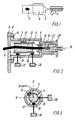
- Fig. 2 is a longitudinal section through an embodiment of the transferring manipulator device according to the invention.
- the manipulator device is mounted on an optical bench (not shown) by means of a vertical supporting plate 6.
- the manipulator device includes a housing 7 provided at its one end with a flange 8 which by screws 9 is tightened against the supporting plate 6.
- the supporting plate 6 has an aperture 10 for passing a laser beam 5 arriving from a laser.
- a supporting tube for an optical glass body 12 is accommodated in the interior of housing 7.
- the housing 7 At its end facing away from the supporting plate 6 the housing 7 is provided with a tube member 13 into which a plug member 14 is inserted.
- Said plug member 14 is tubular as shown and accommodates, on one hand, a beam focusing lens, viz. the previously mentioned optics 4 and, on the other hand, the fibre 1, 2 proper, the function of said plug member being explained later on.
- the housing 7 is further equipped with four screws, e.g. micrometer screws for the adjustment of the tube 11 supporting the glass body 12, viz. two screws in the x-plane (Fig. 2) with heads 15, 16 in abutment against the supporting tube 11 and with associated fingerholds 17 and 18, resp., accessible outside the housing and two similar screws in the y-plane (Fig. 3).
- Fig. 3 only shows the foremost of said two screws in the y-plane, the head 19 abutting against the supporting tube 11 and with associated fingerhold 20 accessible outside the housing, the second one of latter two screws in the y-plane being here located behind the drawing plane of Fig. 3.
- the x-adjusting screw 15, 26 and the associated y-adjusting screw, not shown, are disposed in a plane perpendicular to the optical axis (z-axis) at the end of the supporting tube 11 located closest to the supporting plate 6, while the second x-adjusting screw 16, 18 and the associated y-adjusting screw 19, 20 (Fig. 3) are likewise disposed in a plane perpendicular to the optical axis (z-axis) at the end of the supporting tube 11 closest to the focusing lens 4.
- a spring member 21 made from metal, rubber or an elastomeric material is moreover located between the housing 7 and the supporting tube 11, preferably midway between the first set of the x-y-adjusting screws at one end of the supporting tube 11 and the second set of x-y-adjusting screws 16, 18; 19, 20 (Fig. 3) at the opposite end of the supporting tube 11.
- said spring member 21 is also centred in the bisecting plane between the x-plane and the y-plane, i.e. positioned on the opposite side of the supporting tube 11 in relation to the two sets of x-y-adjusting screws. Said spring member urges the supporting tube 11 against the four screw heads.
- an adjusting ring 22 adapted to effect by rotation trimming of the polarization axis of the fibre relative to the polarization direction of the laser light and to effect by axial displacement a fine trimming of the position of the fibre end in the z-direction.
- the glass body 12 accommodated within the supporting tube it is further observed that it has a plane or substantially plane input face for the arriving laser beam 5 and a curved plane output face for the laser beam passing onto the lens 4.
- the arriving laser beam 5 is received by the input face of the glass body 12, penetrates the glass body, leaves the output face of the glass body, passes onto the focusing lens 4 and is focused by said lens at the end face of the optical fibre.
- a measuring arrangement including for instance light sensitive diodes or optical means con nected to the fibre of the manipulator the light power is measured, the aim being to obtain a maximum light power corresponding to an optimum adjustment in the manipulator.
- a coarse adjustment in the z-direction is effected by axially displacing the fibre 1, 2 in one direction or the other in plug member 14 in housing 7 and fine adjustment by displacing the plug member 14 in relation to the tube member 13 and thus in relation to the housing 7.
- By means of screws 16, 18; 19, 20 closest to the lens 4 a fine adjustment is effected in the x- and y-directions, the supporting tube 11 for the glass body 12 being thereby made to pivot against the force of the spring member 21 urging continuously the supporting tube against the screw heads.
- the angle of the glass body is adjusted in relation to the z-axis, i.e. tilting of the glass body, still against the spring force of the spring member 21.
- This provides for fine trimming of ⁇ x and ⁇ y . It is pointed out that there is no coupling between the angular adjustment and the adjustement of the x-y-position when tilting the glass body 11 in relation to the apex of its curved output face.
- a manipulator device designed as specified above makes it possible to trim the five previously mentioned parameters mutually independently. Due to the shape of the optical, tiltable glass body 12 with plane input face and curved output face a very minute trimming is obtained, since the beam only moves a little, even though the glass body performs a large movement. In reality, and by way of comparison with a mechanical construction without glass body, this provides for obtaining a gearing ratio that is more than ten times better. Per se, this implies moreover the supplementary advantage that due to the down-gearing effect of the glass body there is no need to make use of adjusting screws of very fine tolerances.
- the end face proper of the fibre is encapsulated behind the focusing lens and any optical and movable components are embedded within the housing and thus also protected.
- the plug member 14 may be fully decoupled from the manipulator device and later on plugged in again and that a suitable pre-trimming with a suitable plugging-in efficiency being still ensured, possibly after a desired repeated fine trimming in the z-direction.
Landscapes
- Physics & Mathematics (AREA)
- General Physics & Mathematics (AREA)
- Optics & Photonics (AREA)
- Optical Couplings Of Light Guides (AREA)
- Laser Surgery Devices (AREA)
- Laser Beam Processing (AREA)
Priority Applications (1)
| Application Number | Priority Date | Filing Date | Title |
|---|---|---|---|
| AT88307890T ATE82077T1 (de) | 1987-08-31 | 1988-08-25 | Manipulator zur einkopplung von laserlicht in eine glasfaser. |
Applications Claiming Priority (2)
| Application Number | Priority Date | Filing Date | Title |
|---|---|---|---|
| DK4550/87 | 1987-08-31 | ||
| DK455087A DK158169C (da) | 1987-08-31 | 1987-08-31 | Indkoblingsmanipulator for laserlys til en optisk fiber |
Publications (3)
| Publication Number | Publication Date |
|---|---|
| EP0306220A2 true EP0306220A2 (fr) | 1989-03-08 |
| EP0306220A3 EP0306220A3 (en) | 1989-12-06 |
| EP0306220B1 EP0306220B1 (fr) | 1992-11-04 |
Family
ID=8134550
Family Applications (1)
| Application Number | Title | Priority Date | Filing Date |
|---|---|---|---|
| EP88307890A Expired - Lifetime EP0306220B1 (fr) | 1987-08-31 | 1988-08-25 | Manipulateur pour le transfert de rayonnement laser dans une fibre optique |
Country Status (5)
| Country | Link |
|---|---|
| US (1) | US4886337A (fr) |
| EP (1) | EP0306220B1 (fr) |
| AT (1) | ATE82077T1 (fr) |
| DE (1) | DE3875678T2 (fr) |
| DK (1) | DK158169C (fr) |
Cited By (6)
| Publication number | Priority date | Publication date | Assignee | Title |
|---|---|---|---|---|
| EP0389771A2 (fr) * | 1989-03-27 | 1990-10-03 | Yuji Ikeda | Equipement optique pour un vélocimètre à laser à effet Doppler en fibre optique |
| FR2681951A1 (fr) * | 1991-09-26 | 1993-04-02 | Souriau & Cie | Embase reliant une fibre optique a un composant electro-optique, et outil de centrage de ce composant dans l'embase. |
| EP0877268A2 (fr) * | 1997-05-09 | 1998-11-11 | Point Source Limited | Connecteur pour fibres optiques |
| US6280098B1 (en) | 1997-05-09 | 2001-08-28 | Point Source Limited | Optical fibre connector |
| US7014369B2 (en) | 2002-10-08 | 2006-03-21 | Point Source Limited | Optical fiber connector |
| DE102010047059A1 (de) | 2010-09-30 | 2012-04-05 | Carl Zeiss Meditec Ag | Verfahren und Vorrichtung zur automatischen Laserstrahleinkopplung in Lichtleitfasern |
Families Citing this family (8)
| Publication number | Priority date | Publication date | Assignee | Title |
|---|---|---|---|---|
| KR920010947B1 (ko) * | 1989-05-24 | 1992-12-24 | 가부시끼가이샤 히다찌세이사꾸쇼 | 광결합장치와 그 제조방법, 발광장치와 그 조립방법 및 렌즈홀더 |
| EP0421929B1 (fr) * | 1989-10-03 | 1994-02-23 | Ciba-Geigy Ag | Dispositif pour coupler l'énergie lumineuse d'un faisceau laser dans une fibre optique et procédé pour aligner et surveiller la position de l'extrémité d'une fibre optique |
| US5114422A (en) * | 1989-12-11 | 1992-05-19 | Ioan Cosmescu | Laser laparoscope assembly and method therefor |
| US5638472A (en) * | 1993-04-01 | 1997-06-10 | Optics For Research | Optical fiber and lens assembly having a movable lens and a fixed optical fiber |
| US20050036741A1 (en) * | 2003-03-17 | 2005-02-17 | Mark Rodighiero | Method and apparatus for correcting attachment induced positional shift in a photonic package |
| KR102150575B1 (ko) * | 2013-05-08 | 2020-09-01 | 옵토스칸드 에이비 | 광전자 컴포넌트 |
| JP2019197137A (ja) * | 2018-05-09 | 2019-11-14 | 富士通株式会社 | 光モジュール |
| CN112846489B (zh) * | 2020-12-31 | 2023-03-21 | 浙江迪谱诊断技术有限公司 | 一种可调角度的激光扩束调焦装置 |
Citations (4)
| Publication number | Priority date | Publication date | Assignee | Title |
|---|---|---|---|---|
| CH611429A5 (en) * | 1976-11-18 | 1979-05-31 | France Etat | Device for connecting a laser diode to an optical fibre |
| GB2015766A (en) * | 1978-03-01 | 1979-09-12 | Radiall Sa | Adjustable optic fibre connector |
| US4542956A (en) * | 1982-12-30 | 1985-09-24 | Newport Corporation | Fiber optics transfer systems |
| EP0176024A2 (fr) * | 1984-09-19 | 1986-04-02 | Siemens Aktiengesellschaft | Système de lentilles pour la focalisation d'un faisceau laser divergent |
Family Cites Families (17)
| Publication number | Priority date | Publication date | Assignee | Title |
|---|---|---|---|---|
| DE442558C (de) * | 1927-04-04 | Wilhelm Mathiesen Dr | Heizrohr-Dampferzeuger, insbesondere fuer hohen Druck | |
| DE442454C (de) * | 1926-02-24 | 1927-04-01 | Heinrich Hohl | Bergeversatzmaschine |
| FR2312789A1 (fr) * | 1975-05-27 | 1976-12-24 | Lenoane Georges | Connecteur pour diode a effet laser dans un systeme de transmission par fibres optiques |
| DE2626243C2 (de) * | 1976-06-10 | 1983-01-13 | Aeg-Telefunken Ag, 1000 Berlin Und 6000 Frankfurt | Justierung von optischen Fasern in Koppelelementen |
| YU42693B (en) * | 1981-07-02 | 1988-10-31 | Iskra | Optical connector |
| FR2486664A1 (fr) * | 1980-07-08 | 1982-01-15 | Thomson Csf | Dispositif de jonction des faces emettrice et receptrice de deux elements optiques |
| FR2493535A1 (fr) * | 1980-10-31 | 1982-05-07 | Socapex | Embout pour connecteur de fibre optique et connecteur muni d'un tel embout |
| IT1170643B (it) * | 1981-01-22 | 1987-06-03 | Selenia Ind Elettroniche | Dispositivo perfezionato per l'accoppiamento di un fascio laser ad una fibra ottica |
| US4447119A (en) * | 1981-11-02 | 1984-05-08 | Gould, Inc. | Apparatus for maintaining an optical fiber and a focusing means |
| GB2111239B (en) * | 1981-11-11 | 1985-08-21 | British Telecomm | Optical fibre connector part |
| FR2526961A1 (fr) * | 1982-05-14 | 1983-11-18 | Cilas Alcatel | Dispositif pour connecter un generateur de rayonnement optique et un guide d'onde optique |
| EP0104882B1 (fr) * | 1982-09-29 | 1986-08-27 | THE GENERAL ELECTRIC COMPANY, p.l.c. | Montages pour le couplage d'une fibre optique |
| GB8312650D0 (en) * | 1983-05-07 | 1983-06-08 | Plessey Co Plc | Optical connectors |
| DD218963A1 (de) * | 1983-05-11 | 1985-02-20 | Inst Fuer Nachrichtentechnik | Justierbare, mikrooptische koppelvorrichtung fuer lichtleiter |
| FR2547424B1 (fr) * | 1983-06-08 | 1986-07-04 | Commissariat Energie Atomique | Connecteur optique, procede de fabrication dudit connecteur et connexions fibres - fibres et diodes - fibres realisees avec ce connecteur |
| FR2591761B1 (fr) * | 1985-12-12 | 1989-03-31 | Socapex | Ensemble de collimation deconnectable |
| US4792206A (en) * | 1987-06-01 | 1988-12-20 | The Babcock & Wilcox Company | Method and apparatus for aligning fiber optic cables |
-
1987
- 1987-08-31 DK DK455087A patent/DK158169C/da not_active IP Right Cessation
-
1988
- 1988-08-25 DE DE8888307890T patent/DE3875678T2/de not_active Expired - Fee Related
- 1988-08-25 US US07/236,205 patent/US4886337A/en not_active Expired - Fee Related
- 1988-08-25 AT AT88307890T patent/ATE82077T1/de not_active IP Right Cessation
- 1988-08-25 EP EP88307890A patent/EP0306220B1/fr not_active Expired - Lifetime
Patent Citations (4)
| Publication number | Priority date | Publication date | Assignee | Title |
|---|---|---|---|---|
| CH611429A5 (en) * | 1976-11-18 | 1979-05-31 | France Etat | Device for connecting a laser diode to an optical fibre |
| GB2015766A (en) * | 1978-03-01 | 1979-09-12 | Radiall Sa | Adjustable optic fibre connector |
| US4542956A (en) * | 1982-12-30 | 1985-09-24 | Newport Corporation | Fiber optics transfer systems |
| EP0176024A2 (fr) * | 1984-09-19 | 1986-04-02 | Siemens Aktiengesellschaft | Système de lentilles pour la focalisation d'un faisceau laser divergent |
Cited By (9)
| Publication number | Priority date | Publication date | Assignee | Title |
|---|---|---|---|---|
| EP0389771A2 (fr) * | 1989-03-27 | 1990-10-03 | Yuji Ikeda | Equipement optique pour un vélocimètre à laser à effet Doppler en fibre optique |
| EP0389771A3 (fr) * | 1989-03-27 | 1992-07-08 | Yuji Ikeda | Equipement optique pour un vélocimètre à laser à effet Doppler en fibre optique |
| FR2681951A1 (fr) * | 1991-09-26 | 1993-04-02 | Souriau & Cie | Embase reliant une fibre optique a un composant electro-optique, et outil de centrage de ce composant dans l'embase. |
| EP0877268A2 (fr) * | 1997-05-09 | 1998-11-11 | Point Source Limited | Connecteur pour fibres optiques |
| EP0877268A3 (fr) * | 1997-05-09 | 1999-10-13 | Point Source Limited | Connecteur pour fibres optiques |
| US6276843B1 (en) | 1997-05-09 | 2001-08-21 | Point Source Limited | Adjustable optical fibre connector |
| US6280098B1 (en) | 1997-05-09 | 2001-08-28 | Point Source Limited | Optical fibre connector |
| US7014369B2 (en) | 2002-10-08 | 2006-03-21 | Point Source Limited | Optical fiber connector |
| DE102010047059A1 (de) | 2010-09-30 | 2012-04-05 | Carl Zeiss Meditec Ag | Verfahren und Vorrichtung zur automatischen Laserstrahleinkopplung in Lichtleitfasern |
Also Published As
| Publication number | Publication date |
|---|---|
| EP0306220A3 (en) | 1989-12-06 |
| DE3875678T2 (de) | 1993-04-15 |
| DE3875678D1 (de) | 1992-12-10 |
| US4886337A (en) | 1989-12-12 |
| ATE82077T1 (de) | 1992-11-15 |
| DK455087A (da) | 1989-03-01 |
| DK455087D0 (da) | 1987-08-31 |
| EP0306220B1 (fr) | 1992-11-04 |
| DK158169B (da) | 1990-04-02 |
| DK158169C (da) | 1990-09-03 |
Similar Documents
| Publication | Publication Date | Title |
|---|---|---|
| EP0306220B1 (fr) | Manipulateur pour le transfert de rayonnement laser dans une fibre optique | |
| CA1135545A (fr) | Methode et dispositif de production d'une enveloppe concentrique en bout d'une fibre optique | |
| US5202558A (en) | Flexible fiber optic probe for high-pressure shock experiments | |
| CA1322483C (fr) | Separateur-emetteur de faisceau a rapport variable | |
| JPS587968B2 (ja) | 光フアイバ用コネクタ | |
| CN105247398B (zh) | 光电部件 | |
| US20030035229A1 (en) | Adjustable mount for optical components | |
| US4842391A (en) | Two spherical lens optical coupler | |
| US7764856B2 (en) | Device for injecting light into an optical wave guide | |
| US4447119A (en) | Apparatus for maintaining an optical fiber and a focusing means | |
| CA2195596C (fr) | Dispositif optique a surface terminale de connexion inclinee | |
| US4432601A (en) | Apparatus and method for coupling and decoupling of optical fiber waveguides | |
| US7014369B2 (en) | Optical fiber connector | |
| US5136433A (en) | Optical positioner and connector | |
| US4426055A (en) | Precision translator | |
| WO1992002837A1 (fr) | Support de composant optique | |
| JPH06500867A (ja) | 位置決め装置 | |
| JPH11160569A (ja) | 光結合回路 | |
| US6340248B1 (en) | High precision optical collimator for optical waveguide | |
| US20060127000A1 (en) | Optical fiber coupler | |
| US4852959A (en) | Adjustable fiber optic bulk polarizer | |
| CN216772041U (zh) | 一种多自由度可调节光纤耦合器 | |
| JPH0560935A (ja) | 光フアイバ光線入射位置調整装置 | |
| WO1996010699A1 (fr) | Dispositif de positionnement et procede associe, et dispositif d'alignement d'une fibre optique avec un faisceau optique | |
| JP2587955Y2 (ja) | 光ファイバコリメータ |
Legal Events
| Date | Code | Title | Description |
|---|---|---|---|
| PUAI | Public reference made under article 153(3) epc to a published international application that has entered the european phase |
Free format text: ORIGINAL CODE: 0009012 |
|
| AK | Designated contracting states |
Kind code of ref document: A2 Designated state(s): AT BE CH DE ES FR GB IT LI NL SE |
|
| PUAL | Search report despatched |
Free format text: ORIGINAL CODE: 0009013 |
|
| 17P | Request for examination filed |
Effective date: 19890913 |
|
| AK | Designated contracting states |
Kind code of ref document: A3 Designated state(s): AT BE CH DE ES FR GB IT LI NL SE |
|
| 17Q | First examination report despatched |
Effective date: 19920221 |
|
| GRAA | (expected) grant |
Free format text: ORIGINAL CODE: 0009210 |
|
| AK | Designated contracting states |
Kind code of ref document: B1 Designated state(s): AT BE CH DE ES FR GB IT LI NL SE |
|
| PG25 | Lapsed in a contracting state [announced via postgrant information from national office to epo] |
Ref country code: LI Effective date: 19921104 Ref country code: BE Effective date: 19921104 Ref country code: IT Free format text: LAPSE BECAUSE OF FAILURE TO SUBMIT A TRANSLATION OF THE DESCRIPTION OR TO PAY THE FEE WITHIN THE PRE;WARNING: LAPSES OF ITALIAN PATENTS WITH EFFECTIVE DATE BEFORE 2007 MAY HAVE OCCURRED AT ANY TIME BEFORE 2007. THE CORRECT EFFECTIVE DATE MAY BE DIFFERENT FROM THE ONE RECORDED.SCRIBED TIME-LIMIT Effective date: 19921104 Ref country code: SE Effective date: 19921104 Ref country code: AT Effective date: 19921104 Ref country code: CH Effective date: 19921104 Ref country code: ES Free format text: THE PATENT HAS BEEN ANNULLED BY A DECISION OF A NATIONAL AUTHORITY Effective date: 19921104 |
|
| REF | Corresponds to: |
Ref document number: 82077 Country of ref document: AT Date of ref document: 19921115 Kind code of ref document: T |
|
| REF | Corresponds to: |
Ref document number: 3875678 Country of ref document: DE Date of ref document: 19921210 |
|
| RAP2 | Party data changed (patent owner data changed or rights of a patent transferred) |
Owner name: DANTEC MEASUREMENT TECHNOLOGY A/S |
|
| ET | Fr: translation filed | ||
| REG | Reference to a national code |
Ref country code: CH Ref legal event code: PL |
|
| NLXE | Nl: other communications concerning ep-patents (part 3 heading xe) |
Free format text: PAT.BUL.06/93 PAGES 838 AND 858 CORR.:DANTEC MEASUREMENT TECHNOLOGY A/S |
|
| PLBE | No opposition filed within time limit |
Free format text: ORIGINAL CODE: 0009261 |
|
| STAA | Information on the status of an ep patent application or granted ep patent |
Free format text: STATUS: NO OPPOSITION FILED WITHIN TIME LIMIT |
|
| 26N | No opposition filed | ||
| PGFP | Annual fee paid to national office [announced via postgrant information from national office to epo] |
Ref country code: FR Payment date: 19970729 Year of fee payment: 10 |
|
| PGFP | Annual fee paid to national office [announced via postgrant information from national office to epo] |
Ref country code: GB Payment date: 19970819 Year of fee payment: 10 |
|
| PGFP | Annual fee paid to national office [announced via postgrant information from national office to epo] |
Ref country code: NL Payment date: 19970831 Year of fee payment: 10 |
|
| PGFP | Annual fee paid to national office [announced via postgrant information from national office to epo] |
Ref country code: DE Payment date: 19971028 Year of fee payment: 10 |
|
| PG25 | Lapsed in a contracting state [announced via postgrant information from national office to epo] |
Ref country code: GB Free format text: LAPSE BECAUSE OF NON-PAYMENT OF DUE FEES Effective date: 19980825 |
|
| PG25 | Lapsed in a contracting state [announced via postgrant information from national office to epo] |
Ref country code: NL Free format text: LAPSE BECAUSE OF NON-PAYMENT OF DUE FEES Effective date: 19990301 |
|
| GBPC | Gb: european patent ceased through non-payment of renewal fee |
Effective date: 19980825 |
|
| PG25 | Lapsed in a contracting state [announced via postgrant information from national office to epo] |
Ref country code: FR Free format text: LAPSE BECAUSE OF NON-PAYMENT OF DUE FEES Effective date: 19990430 |
|
| NLV4 | Nl: lapsed or anulled due to non-payment of the annual fee |
Effective date: 19990301 |
|
| PG25 | Lapsed in a contracting state [announced via postgrant information from national office to epo] |
Ref country code: DE Free format text: LAPSE BECAUSE OF NON-PAYMENT OF DUE FEES Effective date: 19990601 |
|
| REG | Reference to a national code |
Ref country code: FR Ref legal event code: ST |