EP0305776B1 - Heizungswasserumwälzpumpe - Google Patents
Heizungswasserumwälzpumpe Download PDFInfo
- Publication number
- EP0305776B1 EP0305776B1 EP88112959A EP88112959A EP0305776B1 EP 0305776 B1 EP0305776 B1 EP 0305776B1 EP 88112959 A EP88112959 A EP 88112959A EP 88112959 A EP88112959 A EP 88112959A EP 0305776 B1 EP0305776 B1 EP 0305776B1
- Authority
- EP
- European Patent Office
- Prior art keywords
- pump
- partition
- diaphragm
- rotor
- impeller
- Prior art date
- Legal status (The legal status is an assumption and is not a legal conclusion. Google has not performed a legal analysis and makes no representation as to the accuracy of the status listed.)
- Expired - Lifetime
Links
- 239000008236 heating water Substances 0.000 title description 5
- 230000005291 magnetic effect Effects 0.000 claims description 9
- 238000005192 partition Methods 0.000 claims description 8
- 238000010438 heat treatment Methods 0.000 claims description 4
- XLYOFNOQVPJJNP-UHFFFAOYSA-N water Substances O XLYOFNOQVPJJNP-UHFFFAOYSA-N 0.000 claims description 4
- 238000000034 method Methods 0.000 claims description 3
- 238000002347 injection Methods 0.000 claims description 2
- 239000007924 injection Substances 0.000 claims description 2
- 238000001746 injection moulding Methods 0.000 claims description 2
- 238000007789 sealing Methods 0.000 claims 4
- 230000005540 biological transmission Effects 0.000 claims 1
- 238000009434 installation Methods 0.000 claims 1
- 230000014759 maintenance of location Effects 0.000 claims 1
- 238000007650 screen-printing Methods 0.000 claims 1
- 229920002994 synthetic fiber Polymers 0.000 claims 1
- 230000008878 coupling Effects 0.000 description 27
- 238000010168 coupling process Methods 0.000 description 27
- 238000005859 coupling reaction Methods 0.000 description 27
- 239000012528 membrane Substances 0.000 description 5
- XEEYBQQBJWHFJM-UHFFFAOYSA-N Iron Chemical compound [Fe] XEEYBQQBJWHFJM-UHFFFAOYSA-N 0.000 description 4
- 238000004519 manufacturing process Methods 0.000 description 4
- 239000000463 material Substances 0.000 description 3
- 239000002245 particle Substances 0.000 description 3
- 238000000151 deposition Methods 0.000 description 2
- 230000005294 ferromagnetic effect Effects 0.000 description 2
- 229910052742 iron Inorganic materials 0.000 description 2
- 230000033001 locomotion Effects 0.000 description 2
- 229920003023 plastic Polymers 0.000 description 2
- 239000004033 plastic Substances 0.000 description 2
- 230000004323 axial length Effects 0.000 description 1
- 238000005266 casting Methods 0.000 description 1
- 238000010276 construction Methods 0.000 description 1
- 238000001816 cooling Methods 0.000 description 1
- 230000008021 deposition Effects 0.000 description 1
- 238000011161 development Methods 0.000 description 1
- 230000018109 developmental process Effects 0.000 description 1
- 239000007788 liquid Substances 0.000 description 1
- 239000000696 magnetic material Substances 0.000 description 1
- 230000005415 magnetization Effects 0.000 description 1
- 239000002184 metal Substances 0.000 description 1
- 229910052751 metal Inorganic materials 0.000 description 1
- 238000013021 overheating Methods 0.000 description 1
- 230000035515 penetration Effects 0.000 description 1
- 230000002035 prolonged effect Effects 0.000 description 1
- 238000007493 shaping process Methods 0.000 description 1
- 238000005245 sintering Methods 0.000 description 1
- 238000009987 spinning Methods 0.000 description 1
- 238000005406 washing Methods 0.000 description 1
- 238000004804 winding Methods 0.000 description 1
Images
Classifications
-
- H—ELECTRICITY
- H02—GENERATION; CONVERSION OR DISTRIBUTION OF ELECTRIC POWER
- H02K—DYNAMO-ELECTRIC MACHINES
- H02K7/00—Arrangements for handling mechanical energy structurally associated with dynamo-electric machines, e.g. structural association with mechanical driving motors or auxiliary dynamo-electric machines
- H02K7/10—Structural association with clutches, brakes, gears, pulleys or mechanical starters
- H02K7/11—Structural association with clutches, brakes, gears, pulleys or mechanical starters with dynamo-electric clutches
-
- F—MECHANICAL ENGINEERING; LIGHTING; HEATING; WEAPONS; BLASTING
- F04—POSITIVE - DISPLACEMENT MACHINES FOR LIQUIDS; PUMPS FOR LIQUIDS OR ELASTIC FLUIDS
- F04D—NON-POSITIVE-DISPLACEMENT PUMPS
- F04D13/00—Pumping installations or systems
- F04D13/02—Units comprising pumps and their driving means
- F04D13/021—Units comprising pumps and their driving means containing a coupling
- F04D13/024—Units comprising pumps and their driving means containing a coupling a magnetic coupling
- F04D13/025—Details of the can separating the pump and drive area
-
- F—MECHANICAL ENGINEERING; LIGHTING; HEATING; WEAPONS; BLASTING
- F04—POSITIVE - DISPLACEMENT MACHINES FOR LIQUIDS; PUMPS FOR LIQUIDS OR ELASTIC FLUIDS
- F04D—NON-POSITIVE-DISPLACEMENT PUMPS
- F04D13/00—Pumping installations or systems
- F04D13/02—Units comprising pumps and their driving means
- F04D13/021—Units comprising pumps and their driving means containing a coupling
- F04D13/024—Units comprising pumps and their driving means containing a coupling a magnetic coupling
- F04D13/026—Details of the bearings
Definitions
- the invention relates to a circulation pump with an electric motor drive for hot water heating systems of the type specified in the preamble of claim 1.
- DE-GBM 19 12 189 it is known to provide a permanent magnetic coupling in heating water circulation pumps between the electric motor and the pump wheel for transmitting the torque, the two coupling halves of which are separated from one another in a liquid-tight manner by a diaphragm-like intermediate wall.
- the pump is also separated from the drive motor in a liquid-tight manner and it is possible to use an electric motor of a conventional type as a pump drive.
- the disadvantage is the relatively poor efficiency of such an arrangement, particularly when the driven coupling half is designed only as a soft magnetic return plate.
- a circulation pump is known from EP-A 217 235, which can be used as a drain pump with a magnetic coupling in a washing machine or in a dishwasher. Due to the design, this pump is less suitable for a hot water heating system.
- a magnetically driven centrifugal pump is also known from US Pat. No. 2,669,668, but is driven separately and contains no built-in drive motor at all.
- the present invention is therefore based on the object to improve a heating water circulation pump of the type described in terms of its design so far that an optimal efficiency of both the clutch and the entire pump unit is reached and its operational safety is improved.
- the possibility should be created to carry out the assembly as far as possible by using automatic manufacturing machines.
- the invention has the advantage that due to the arrangement of the motor rotor and the pump wheel on a common axis a perfect central alignment of these two components, but in particular the coupling halves arranged between the two components is achieved. This in turn results in a considerable increase in the transferable clutch output while at the same time reducing the axial length.
- the manufacture of the diaphragm and the B-side engine end shield as plastic injection molded parts simplifies the structure of the arrangement and lowers the assembly costs.
- the invention achieves an improvement in the efficiency of the pump with little effort on the one hand because of the small wall thickness of the membrane and on the other hand prevents foreign bodies from entering the area between the coupling and the membrane. In particular, the depositing of ferromagnetic particles on the magnetic ring is prevented.
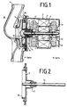
- the pump arrangement is shown in cross section in FIG. 1.
- the drive motor which is designed, for example, as a two-pole asynchronous motor, has a stator 1 and a rotor 2 and is accommodated in a housing 3, the construction of which corresponds to the prescribed degree of protection.
- the rotor 2 rotates about the fixed axis 11 and is supported thereon by means of the bearings 7.
- the A-side short-circuit ring of the rotor 2 is extended beyond the winding head space of the stator 1 and carries the motor-side coupling half 15 at its free end.
- the axis 11 forms the central component around which the motor-pump arrangement is constructed.
- the axis 11 is fastened on the one hand in a section 17 of the diaphragm-like intermediate wall 4 which is specially designed for this purpose and on the other hand in the B-side end plate of the drive motor.
- the rotor 2 is mounted between these two attachment points of the axis 11 in any way.
- the free end 18 of the axis 11 protrudes into the pump chamber and carries a bearing 20 for receiving the coupling half 16 on the pump side and the pump wheel
- the circulation pump 30 is designed as a centrifugal pump and has a housing 6 which is essentially helical.
- the pump wheel 5 rotating in the housing 6 is connected on its side facing the drive motor to the pump-side coupling half 16 in a rotationally fixed manner, for example by partially overmolding with the material of the pump wheel 5.
- the bearing 20 can also be fastened.
- the B-side bearing plate 19 is preferably formed in one piece with the motor housing 3 and carries a receptacle 13 for the axis 11, which is held therein in a non-rotatable and axially non-displaceable manner, centrally to the motor axis.
- the B-side bearing plate also serves to relieve the diaphragm-like intermediate wall 4 via the axis 11 of the pressure prevailing in the heating system and acting on the diaphragm.
- the axis 11 carries in a notch the Simmerring 22, which rests directly on the receptacle 13.
- the side of the pump housing 6 facing the drive motor is covered in a liquid-tight manner by the intermediate wall 4, which is thin in the form of a membrane in the region of the two coupling halves 15 and 16 assigned to one another.
- the intermediate wall 4 has a section 17 in the center, in the exemplary embodiment described centering on the membrane, the section of which is designed to accommodate and hold the axis 11.
- the section of the intermediate wall 4 which is in contact with the housing 6 is connected to the housing 6 in a liquid-tight or detachable manner.
- the partition wall by arranging one or more annular projections 10, which are operatively connected to corresponding counterparts on the pump wheel, forms a labyrinth seal which is intended to prevent the penetration of foreign bodies into the area between the coupling and the membrane.
- the coupling between the drive motor and the pump wheel consists of the coupling halves 15 and 16, which can be fastened to the components assigned to them in the manner described, but also in a different way.
- Both coupling halves 15 and 16 are designed as permanent magnets in one or more parts.
- annular permanent magnets are used. These are magnetized in such a way that - seen in the circumferential direction - the north and south poles alternate in succession, ie a so-called "star-shaped" magnetization is provided.
- a total of eight opposing magnetic poles are arranged on each clutch disc.
- the size of the torque to be transmitted between the two coupling halves is distributed unevenly over the coupling circumference, that is to say sections which transmit a large amount Allow torque, alternate with sections within which only lower torque can be transmitted.
- the torque that can be transmitted by the clutch is greater than the tilting torque of the drive motor.
- the drive motor also stops, so that there is no rotational movement between the coupling halves and therefore no overheating of the magnetic disks as a result of the spinning of only one coupling half is possible.
- the drive motor it is disconnected from the mains via a heat sensor, motion detectors or other suitable means when the coupling is stationary.
- the pump housing is designed such that a space is arranged between the pump wheel and the coupling half attached to it sets a very high flow rate of the liquid to be conveyed, so that the particles are entrained and cannot settle on the magnetic ring.
- This intermediate space is formed, for example, by enlarging the space radially surrounding the coupling half 16.
- the coupling halves advantageously consist of a permanent magnetic material, the field strength of which, even at the maximum operating temperature of the heating water - approximately 110 ° - is sufficiently large to transmit a torque exceeding the overturning moment of the drive motor.
- the ring-shaped coupling halves 15, 16, which are preferably produced in the sintering process, are balanced in that, in the region of the periphery of each coupling half 15, 16, blind holes are already pressed in during their manufacture and are filled with balancing mass as required.
- the pump housing 6 also has a structural design of the housing walls, which makes it possible to use a casting mold with only two core pulling directions.
- the motor housing 3 is preferably designed as a drip-proof housing and has cooling air openings covered against dripping water.
Landscapes
- Engineering & Computer Science (AREA)
- Mechanical Engineering (AREA)
- General Engineering & Computer Science (AREA)
- Power Engineering (AREA)
- Structures Of Non-Positive Displacement Pumps (AREA)
- Sealing Of Bearings (AREA)
Applications Claiming Priority (2)
| Application Number | Priority Date | Filing Date | Title |
|---|---|---|---|
| DE3727758 | 1987-08-20 | ||
| DE19873727758 DE3727758A1 (de) | 1987-08-20 | 1987-08-20 | Heizungswasserumwaelzpumpe |
Publications (2)
| Publication Number | Publication Date |
|---|---|
| EP0305776A1 EP0305776A1 (de) | 1989-03-08 |
| EP0305776B1 true EP0305776B1 (de) | 1993-05-05 |
Family
ID=6334116
Family Applications (1)
| Application Number | Title | Priority Date | Filing Date |
|---|---|---|---|
| EP88112959A Expired - Lifetime EP0305776B1 (de) | 1987-08-20 | 1988-08-10 | Heizungswasserumwälzpumpe |
Country Status (2)
| Country | Link |
|---|---|
| EP (1) | EP0305776B1 (enExample) |
| DE (2) | DE3727758A1 (enExample) |
Families Citing this family (4)
| Publication number | Priority date | Publication date | Assignee | Title |
|---|---|---|---|---|
| DE3831457A1 (de) * | 1988-09-16 | 1990-03-22 | Licentia Gmbh | Elektromotorisch angetriebene fluessigkeitspumpe |
| US5269664A (en) * | 1992-09-16 | 1993-12-14 | Ingersoll-Dresser Pump Company | Magnetically coupled centrifugal pump |
| CN1059489C (zh) * | 1994-07-08 | 2000-12-13 | 株式会社三协精机制作所 | 给水泵 |
| JP4796319B2 (ja) * | 2005-03-29 | 2011-10-19 | 日本電産サンキョー株式会社 | 磁気結合ポンプ装置 |
Family Cites Families (7)
| Publication number | Priority date | Publication date | Assignee | Title |
|---|---|---|---|---|
| US2669668A (en) * | 1949-02-05 | 1954-02-16 | Hermag Pumps Ltd | Magnetically driven centrifugal pump |
| US2724784A (en) * | 1951-09-01 | 1955-11-22 | Fmc Corp | Magnetic power transmission |
| US2951447A (en) * | 1958-07-31 | 1960-09-06 | Gen Motors Corp | Impeller pumps with magnentic drives |
| DE1528768A1 (de) * | 1965-03-25 | 1970-02-12 | Micro Electric Ag | Fluessigkeitsfoerderaggregat |
| FR91540E (fr) * | 1966-03-10 | 1968-06-28 | Unelec | électropompe rotative à entrefer radial |
| US3649137A (en) * | 1970-11-30 | 1972-03-14 | Nikolaus Laing | Centrifugal pump with magnetic coupling |
| IT1187296B (it) * | 1985-09-20 | 1987-12-23 | Zanussi Elettromecc | Elettropompa a trascinamento magnetico |
-
1987
- 1987-08-20 DE DE19873727758 patent/DE3727758A1/de active Granted
-
1988
- 1988-08-10 DE DE8888112959T patent/DE3880765D1/de not_active Expired - Fee Related
- 1988-08-10 EP EP88112959A patent/EP0305776B1/de not_active Expired - Lifetime
Also Published As
| Publication number | Publication date |
|---|---|
| DE3727758A1 (de) | 1989-03-02 |
| EP0305776A1 (de) | 1989-03-08 |
| DE3727758C2 (enExample) | 1991-06-06 |
| DE3880765D1 (de) | 1993-06-09 |
Similar Documents
| Publication | Publication Date | Title |
|---|---|---|
| EP0408988B1 (de) | Elektrischer Universalmotor | |
| EP0160971B1 (de) | Lagerung für Antriebsmotor eines kleinstventilators | |
| EP1115981B1 (de) | Flüssigkeitspumpe mit klauenpolstator | |
| DE19956380C1 (de) | Flüssigkeitspumpe mit einem Motorgehäuse und Verfahren zur Herstellung eines Motorgehäuses | |
| EP1329014B1 (de) | Rotorbaugruppe für einen elektromotor und innenläufer-elektromotor | |
| EP1256722B1 (de) | Kreiselpumpe | |
| DE3780847T2 (de) | Pumpe. | |
| EP0780506A1 (de) | Antriebsvorrichtung für eine von vorn beschickbare Waschmaschine | |
| EP0780507A2 (de) | Antriebsvorrichtung für eine von vorn beschickbare Waschmaschine | |
| DE19845864A1 (de) | Spaltrohrmotor | |
| DE19922610A1 (de) | Antriebsvorrichtung für eine Waschmaschine | |
| DE3922261A1 (de) | Anker fuer einen elektromotor sowie verfahren zur herstellung eines solchen ankers | |
| DE102011079226A1 (de) | Flüssigkeitspumpe, insbesondere Wasserpumpe | |
| DE102017206091B3 (de) | Elektrischer Antriebsmotor, Nassläufer-Pumpe und Haushaltsgerät, sowie Verfahren zur Herstellung eines solchen elektrischen Antriebsmotors | |
| DE2307800C3 (de) | Kollektorloser Gleichstrommotor für hohe Drehzahlen | |
| EP0305776B1 (de) | Heizungswasserumwälzpumpe | |
| CH444674A (de) | Aus einer Umwälzpumpe und einem zu deren Antrieb dienenden Elektromotor bestehendes Aggregat | |
| EP0282755B1 (de) | Spaltrohrmotor | |
| EP0491424B2 (de) | Elektrisches Haushaltsgerät | |
| EP0274150B1 (de) | Einphasensynchronmotor mit einem zweipoligen, dauermagnetischen Rotor und mit einem Wirbelstrom-Zwischenläufer | |
| WO2019233874A1 (de) | Elektrischer antriebsmotor, nassläufer-pumpe und haushaltsgerät | |
| DE4303479C2 (de) | Pumpenaggregat mit einem drehzahlregelbaren Elektromtor | |
| DE69631461T2 (de) | Radnabendynamo für ein Fahrrad | |
| DE69108250T2 (de) | Zentrifugalmotorpumpe. | |
| DE2539492A1 (de) | Vorrichtung zum verbinden eines elektromotors mit einem arbeitsgeraet |
Legal Events
| Date | Code | Title | Description |
|---|---|---|---|
| PUAI | Public reference made under article 153(3) epc to a published international application that has entered the european phase |
Free format text: ORIGINAL CODE: 0009012 |
|
| AK | Designated contracting states |
Kind code of ref document: A1 Designated state(s): DE FR GB IT |
|
| 17P | Request for examination filed |
Effective date: 19890329 |
|
| 17Q | First examination report despatched |
Effective date: 19900621 |
|
| GRAA | (expected) grant |
Free format text: ORIGINAL CODE: 0009210 |
|
| AK | Designated contracting states |
Kind code of ref document: B1 Designated state(s): DE FR GB IT |
|
| PG25 | Lapsed in a contracting state [announced via postgrant information from national office to epo] |
Ref country code: IT Free format text: LAPSE BECAUSE OF FAILURE TO SUBMIT A TRANSLATION OF THE DESCRIPTION OR TO PAY THE FEE WITHIN THE PRE;WARNING: LAPSES OF ITALIAN PATENTS WITH EFFECTIVE DATE BEFORE 2007 MAY HAVE OCCURRED AT ANY TIME BEFORE 2007. THE CORRECT EFFECTIVE DATE MAY BE DIFFERENT FROM THE ONE RECORDED.SCRIBED TIME-LIMIT Effective date: 19930505 Ref country code: GB Effective date: 19930505 Ref country code: FR Effective date: 19930505 |
|
| REF | Corresponds to: |
Ref document number: 3880765 Country of ref document: DE Date of ref document: 19930609 |
|
| EN | Fr: translation not filed | ||
| GBV | Gb: ep patent (uk) treated as always having been void in accordance with gb section 77(7)/1977 [no translation filed] |
Effective date: 19930505 |
|
| PLBE | No opposition filed within time limit |
Free format text: ORIGINAL CODE: 0009261 |
|
| STAA | Information on the status of an ep patent application or granted ep patent |
Free format text: STATUS: NO OPPOSITION FILED WITHIN TIME LIMIT |
|
| 26N | No opposition filed | ||
| PGFP | Annual fee paid to national office [announced via postgrant information from national office to epo] |
Ref country code: DE Payment date: 19951031 Year of fee payment: 8 |
|
| PG25 | Lapsed in a contracting state [announced via postgrant information from national office to epo] |
Ref country code: DE Effective date: 19970501 |