EP0304513B1 - Low-voltage lighting system - Google Patents
Low-voltage lighting system Download PDFInfo
- Publication number
- EP0304513B1 EP0304513B1 EP87119214A EP87119214A EP0304513B1 EP 0304513 B1 EP0304513 B1 EP 0304513B1 EP 87119214 A EP87119214 A EP 87119214A EP 87119214 A EP87119214 A EP 87119214A EP 0304513 B1 EP0304513 B1 EP 0304513B1
- Authority
- EP
- European Patent Office
- Prior art keywords
- bars
- low
- lighting system
- contact
- voltage lighting
- Prior art date
- Legal status (The legal status is an assumption and is not a legal conclusion. Google has not performed a legal analysis and makes no representation as to the accuracy of the status listed.)
- Expired - Lifetime
Links
- 229910000831 Steel Inorganic materials 0.000 claims description 18
- 239000010959 steel Substances 0.000 claims description 18
- 239000002390 adhesive tape Substances 0.000 claims description 4
- 239000000696 magnetic material Substances 0.000 claims description 4
- 230000002093 peripheral effect Effects 0.000 claims 1
- 239000004020 conductor Substances 0.000 description 14
- 239000010410 layer Substances 0.000 description 13
- 238000004519 manufacturing process Methods 0.000 description 6
- 238000009413 insulation Methods 0.000 description 5
- 239000002023 wood Substances 0.000 description 4
- 230000007935 neutral effect Effects 0.000 description 3
- JXYWFNAQESKDNC-BTJKTKAUSA-N (z)-4-hydroxy-4-oxobut-2-enoate;2-[(4-methoxyphenyl)methyl-pyridin-2-ylamino]ethyl-dimethylazanium Chemical compound OC(=O)\C=C/C(O)=O.C1=CC(OC)=CC=C1CN(CCN(C)C)C1=CC=CC=N1 JXYWFNAQESKDNC-BTJKTKAUSA-N 0.000 description 2
- 229910052751 metal Inorganic materials 0.000 description 2
- 239000002184 metal Substances 0.000 description 2
- 239000012811 non-conductive material Substances 0.000 description 2
- RYGMFSIKBFXOCR-UHFFFAOYSA-N Copper Chemical compound [Cu] RYGMFSIKBFXOCR-UHFFFAOYSA-N 0.000 description 1
- CWYNVVGOOAEACU-UHFFFAOYSA-N Fe2+ Chemical compound [Fe+2] CWYNVVGOOAEACU-UHFFFAOYSA-N 0.000 description 1
- 239000000853 adhesive Substances 0.000 description 1
- 230000001070 adhesive effect Effects 0.000 description 1
- 239000012790 adhesive layer Substances 0.000 description 1
- 229910052782 aluminium Inorganic materials 0.000 description 1
- XAGFODPZIPBFFR-UHFFFAOYSA-N aluminium Chemical compound [Al] XAGFODPZIPBFFR-UHFFFAOYSA-N 0.000 description 1
- 238000010276 construction Methods 0.000 description 1
- 229910052802 copper Inorganic materials 0.000 description 1
- 239000010949 copper Substances 0.000 description 1
- 239000003000 extruded plastic Substances 0.000 description 1
- 238000001125 extrusion Methods 0.000 description 1
- 239000012774 insulation material Substances 0.000 description 1
- 239000000463 material Substances 0.000 description 1
- 239000004033 plastic Substances 0.000 description 1
- 229910001220 stainless steel Inorganic materials 0.000 description 1
- 239000010935 stainless steel Substances 0.000 description 1
- 239000000758 substrate Substances 0.000 description 1
- 230000007704 transition Effects 0.000 description 1
Images

Classifications
-
- H—ELECTRICITY
- H01—ELECTRIC ELEMENTS
- H01R—ELECTRICALLY-CONDUCTIVE CONNECTIONS; STRUCTURAL ASSOCIATIONS OF A PLURALITY OF MUTUALLY-INSULATED ELECTRICAL CONNECTING ELEMENTS; COUPLING DEVICES; CURRENT COLLECTORS
- H01R25/00—Coupling parts adapted for simultaneous co-operation with two or more identical counterparts, e.g. for distributing energy to two or more circuits
- H01R25/14—Rails or bus-bars constructed so that the counterparts can be connected thereto at any point along their length
- H01R25/142—Their counterparts
-
- F—MECHANICAL ENGINEERING; LIGHTING; HEATING; WEAPONS; BLASTING
- F21—LIGHTING
- F21V—FUNCTIONAL FEATURES OR DETAILS OF LIGHTING DEVICES OR SYSTEMS THEREOF; STRUCTURAL COMBINATIONS OF LIGHTING DEVICES WITH OTHER ARTICLES, NOT OTHERWISE PROVIDED FOR
- F21V21/00—Supporting, suspending, or attaching arrangements for lighting devices; Hand grips
- F21V21/34—Supporting elements displaceable along a guiding element
- F21V21/35—Supporting elements displaceable along a guiding element with direct electrical contact between the supporting element and electric conductors running along the guiding element
-
- F—MECHANICAL ENGINEERING; LIGHTING; HEATING; WEAPONS; BLASTING
- F21—LIGHTING
- F21V—FUNCTIONAL FEATURES OR DETAILS OF LIGHTING DEVICES OR SYSTEMS THEREOF; STRUCTURAL COMBINATIONS OF LIGHTING DEVICES WITH OTHER ARTICLES, NOT OTHERWISE PROVIDED FOR
- F21V21/00—Supporting, suspending, or attaching arrangements for lighting devices; Hand grips
- F21V21/14—Adjustable mountings
- F21V21/30—Pivoted housings or frames
-
- H—ELECTRICITY
- H01—ELECTRIC ELEMENTS
- H01R—ELECTRICALLY-CONDUCTIVE CONNECTIONS; STRUCTURAL ASSOCIATIONS OF A PLURALITY OF MUTUALLY-INSULATED ELECTRICAL CONNECTING ELEMENTS; COUPLING DEVICES; CURRENT COLLECTORS
- H01R13/00—Details of coupling devices of the kinds covered by groups H01R12/70 or H01R24/00 - H01R33/00
- H01R13/62—Means for facilitating engagement or disengagement of coupling parts or for holding them in engagement
- H01R13/6205—Two-part coupling devices held in engagement by a magnet
Definitions
- the invention relates to a low-voltage lighting system consisting of at least one busbar that can be fastened to the ground and lighting bodies that can be fastened to it by means of adapters, the busbar consisting of at least two rods made of magnetic material which are arranged parallel to one another and have different electrical potential and are separated from one another by an insulating layer are and are held together by this.
- Lighting systems which have busbars which are arranged parallel to one another and are separated from one another by an insulating layer, the rods being embedded in this insulating layer over a large part of their circumference. Only two surfaces of the rods, which are opposite each other by 180 degrees, are free of the insulation. This results in a busbar of approximately circular cross section. Since the contact surfaces of the two rods lie diametrically opposite one another, the adapters for fastening the lighting fixtures to the busbar are designed in the form of a clamp. The clamp legs touching the contact surfaces serve to establish the electrical contact from the busbar to the lighting fixture. The production of such busbars is complex since the rods have to be cast into the insulation material.
- the clamp legs are pressed against the contact surfaces of the busbar with the aid of a spring. Since the lighting systems according to the invention should be variable in the arrangement of the lighting fixtures on the rails, it is necessary that the lighting fixtures can be moved quickly and easily on the rail.
- the clamp adapters have the disadvantage that the material of the clamp spring becomes fatigued when the lighting fixtures are frequently moved, and thus a firm hold on the rail is no longer guaranteed.
- the production of the clip adapter is complex. Inevitably, these adapters require a construction whose transverse expansion is significantly larger than the conductor rail diameter. If the premises to be illuminated require that several busbars are arranged closely next to one another, the distance between individual busbars is limited by the expansion of the brackets in order to avoid short circuits.
- the previously known system has the disadvantage that the busbars are limited to two current-carrying rods united in them.
- the busbars are limited to two current-carrying rods united in them.
- French patent FR-A-1 400 179 also discloses a low-voltage lighting system with stainless steel busbars attached to the base and adapters for the lighting fixtures held magnetically thereon, in which the adapters consist of permanent magnetic material and two parallel to one another in one plane have arranged, electrically conductive contact surfaces which are placed directly on the parallel surfaces of the busbars and are thereby mechanically and electrically connected.
- the invention is therefore based on the object of providing a low-voltage lighting system of the type mentioned at the outset which is simple to produce, allows the adapters to be connected in more than one direction and in which the busbar is not limited to two current-carrying rods.
- the invention consists in that the insulating layer between the mutually facing surfaces of the neighboring Rods connects them to each other to form a busbar and the contact surfaces of the adapters are separated from one another by an electrically non-conductive permanent magnet and fastened to it.
- the bars are largely exposed and are only separated from the insulating layer on the surfaces of adjacent bars facing one another.
- the insulating layer can e.g. B. be an adhesive tape, so that the insulating layer also causes the cohesion of the rods in the busbar.
- the contact surfaces of the busbar lie next to one another in one plane, adapters with contact surfaces likewise lying in one plane can be used.
- the contact surfaces are attached to a permanent magnet arranged between them, so that the contact surfaces also become magnetic.
- the busbars according to the invention also offer the advantage that contact surfaces are present both on the top and on the bottom of the busbar. If the busbar is attached at a sufficient distance from the surface, e.g. B. by hanging the track from the ceiling, lighting fixtures can be attached to it both on the lower and on the upper side. The lighting fixtures can be directed in such a way that some of them illuminate the surface and thus generate indirect lighting and another part of the lighting fixtures is directed directly into the room as a spotlight. Because the adapters have a transverse extent which corresponds approximately to the distance between the longitudinal axes of the rods, the distances between individual busbars are minimally small. In addition, the manufacture of the adapter according to the invention and the manufacture of the busbars are considerably simplified.
- the rods can be rectangular in cross section, for. B. be square, which makes the production of the busbars from such rods even easier.
- each facing sides of the rods are flattened and serve as fastening surfaces for the insulating layer.
- Claim 6 has a further advantageous feature of the adapter according to the invention. This makes it possible to quickly and easily separate the lighting fixture from the adapter and the free one Use the adapter as a fastening element for the busbars on the surface.
- the feature of claim 7 offers the advantage of being able to detach the lighting fixtures quickly and easily from the line elements which are attached to the adapter and to replace them with a different type of lighting fixture.
- busbars according to the invention is given by the feature of claim 8. If the insulating layer on both sides of the busbar protrudes beyond the plane formed by the contact surfaces of adjacent rods, rotation of the contact surfaces of the adapters in this plane cannot lead to a short circuit, since the web-shaped design of the insulating layer prevents the contact surfaces of the adapter from twisting the contact surfaces of the conductor rail.
- the features of claim 10 provide a magnetic adapter which is provided for fastening the busbars to the substrate, a wall or a ceiling. Its structure is identical to that of the lighting fixture adapter. As already stated above, the magnetic adapters are designed in such a way that they can be used either as a fastening element for the lighting fixtures or as a fastening element for the busbars themselves.
- An alternative fastening option is given by claim 11.
- About 2 cm long sleeves are attached to the outer bars of the busbar and z. B. attached with grub screws to the bars.
- Two opposite sleeves are on a z. B. cube-shaped base, e.g. B. made of plastic, screwed tight.
- the base On its surface facing away from the busbar, the base has a blind hole into which the bolt of a screw is inserted, which is anchored to the base.
- a further hole is made in the side of the base, which opens into the blind hole.
- the bore has a Internal thread into which a grub screw can be screwed, which presses against the screw bolt when it is tightened and holds it in place.
- a socket for connecting the power supply lines can be attached to each of the sleeves.
- the lighting system according to the invention is not limited to busbars with only two rods combined to form a busbar.
- the busbar consists of three rods arranged parallel to each other, with adjacent rods having different electrical potentials.
- the insulating layer is arranged between two rods in such a way that the contact surfaces of the three rods arranged parallel to one another lie in one plane.
- the middle rod is preferably the neutral conductor, while the outer rods represent the phases.
- the features of claim 13 provide a further busbar in which a total of eight rods are combined to form a busbar which is approximately square in cross section. Three adjacent bars form the sides of the square. The spaces between the bars are one insulating mass filled. If square bars are used to form the busbar, two adjacent bars can be connected to one another with the aid of an insulating adhesive.
- the insulation body is advantageously designed as an extrusion part, so that the rods can be introduced into channels provided for this purpose. With the aid of such a rail, it is possible to implement a four-phase system, the rods enclosed by two outer rods being used as neutral conductors and the outer rods attached to the edges representing the four phases.
- the rods can, for. B. consist of a steel tube of small diameter, which has a core made of a non-ferrous metal, for. B. surrounds copper or aluminum.
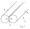
- a conductor rail (1) is shown in broken representation, which consists of two round steels (2 and 3), which have flat surfaces (4 and 5) on their mutually facing sides.
- the flat sides (4 and 5) of the rods (2 and 3) are attached to an insulating adhesive tape (6) which separates and insulates the rods (2 and 3) along their entire length.
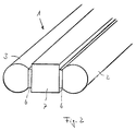
- FIG. 2 shows a further embodiment of a busbar according to the invention in a broken view.
- This consists of three parallel bars (2, 3 and 7).
- the rods (2 and 3) are designed as in Fig. 1, while the intermediate rod is rectangular in cross section.
- the rods are connected to one another along their entire length by an insulating adhesive layer (6).
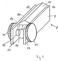
- FIG. 3 shows a magnetic adapter (8) according to the invention. It consists of two steel sheets (9 and 10) which are arranged parallel to one another and are rectangular in outline and which are separated from one another by means of a magnet (11) which consists of a non-conductive material are separated.
- the steel sheets (9 and 10) are attached to the opposite side surfaces of the magnet (11), for. B. glued.
- the contact surfaces (12 and 13) that make contact with the busbar (1) protrude beyond the upper edge (14) of the magnet (11).
- the magnet (11) On its surface facing the busbar, the magnet (11) has a roof-shaped web (15) which is also made of non-conductive material. It is used so that when an adapter (8) is rotated on a busbar according to FIGS.
- the contact surfaces (12 and 13) are lifted off the contact surfaces of the busbar (1), thus preventing a short circuit.
- the steel sheets (9 and 10) are extended beyond the front edge of the magnet (11).
- the extensions (16 and 17) are provided with bores (18) through which the screw bolt (19) of screws (20 and 21) can be inserted.
- the screws (20 and 21) are used to fasten conductor elements, not shown, which are connected to a lighting fixture, also not shown.
- FIG. 4 shows a busbar (1) in which the insulating layer (6) is extended beyond the contact surfaces of the rods (2 and 3) in the form of a web.
- an adapter (8) is used, as is shown in FIG. 3.
- the roof-shaped web is here (15) omitted.
- the web (22) extends approximately to the surface of the magnet (11). This also prevents a short circuit when the adapter (8) is rotated on the busbar, since the web causes the contact surfaces (12 and 13) of the adapter (8) to lift off.
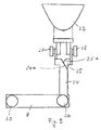
- An adapter (8) with a connected lighting fixture (23) is arranged on the busbar (1). With the aid of the screws (20 and 21), a conductor element (24 and 25) is fastened to the projecting ends (16 and 17) of the steel sheets (9 and 10). They are constructed identically and consist of a metal sheet which has an approximately L-shaped outline, the end of the larger leg of the L being bent by 90 degrees.
- the L-shaped conductor elements (24, 25) have a chamfer (24 a, 25 a) at the transition from the vertical to the horizontal L-leg. These bevels are necessary so that when the lighting fixture (23) is pivoted about an axis that leads through the screw axis of the screws (27 and 28), no short circuit can occur.
- fastenings for the lighting fixture (23) in the form of screws (27 and 28) are provided, which at the same time the electrical Form contact between the conductor elements (24 and 25) and the connections of the lighting fixture (23).
- lighting fixtures (23) can be arranged at both ends of the adapter (8).
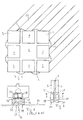
- busbars according to the invention are shown. They have a square cross section, each side of the square consisting of three bars (2, 3, 7), between which an insulation body (6) is arranged.
- the insulation body (6) can consist of adhesive tapes which combine the bars to form the busbar.
- the insulation body it is also possible to design the insulation body as an extruded plastic profile, as is generally provided for busbars consisting of round bars. The rods are pushed into the extruded profile from one side and can also be glued to it.
- the base (34) With the help of the screws (33), the base (34) is firmly connected to the sleeves (30).
- a blind hole (not shown) is made in the surface (35) of the base (34) opposite the busbar.
- the screw bolt of a merely indicated wood screw (36) is inserted in this blind hole.
- the wood screw (36) is previously in the underground (37), for. B. wall pegged.
- the base (34) with the blind hole is pushed onto the screw bolt of the screw (36).
- the bore also has an internal thread into which a grub screw can be screwed, which, when the base (34) is placed on the wood screw, rests against the screw bolt of the wood screw (36) presses and the base is fixed on the surface.
- the sleeves can have not shown, but only indicated connection sockets for the power supply.
- the sleeves (30) can be attached at any point on the busbar. There they can be attached to the base using the base (34). However, they can also serve as connecting elements of two aligned busbars without the base. In addition, it is possible to use the sleeves (30), for. B. hanging from the ceiling. It is also possible to connect two sleeves (30) aligned with one another with the aid of a flexible intermediate piece. In this way, two busbars can be attached to each other so that they can be offset from each other by any angle.
- a lighting system is constructed as follows: Adapters (8) which are aligned with one another in the longitudinal direction are fastened to a wall or a ceiling. Busbars (1) are attached to these adapters (8). The power connections of the low-voltage voltage source are at two ends (16 and 17) of one of the adapters, e.g. B. with the screws (20 and 21). On the side of the The busbar (1) is fitted with an adapter (8) equipped with a lighting fixture (23), so that the circuit is closed. Several such rails can be arranged on the ceiling or on the wall, and the lighting elements can be moved on the conductor rails in order to produce a wide variety of lighting configurations.
Landscapes
- Engineering & Computer Science (AREA)
- General Engineering & Computer Science (AREA)
- Non-Portable Lighting Devices Or Systems Thereof (AREA)
Description
Die Erfindung betrifft ein Niedervolt-Beleuchtungssystem bestehend aus mindestens einer am Untergrund befestigbaren Stromschiene und daran mittels Adaptern befestigbaren Beleuchtungskörpern, wobei die Stromschiene aus mindestens zwei parallel zueinander angeordneten, auf unterschiedlichem elektrischen Potential liegenden Stangen aus magnetischem Material bestehen, die voneinander durch eine isolierende Schicht getrennt sind und von dieser zusammengehalten werden.The invention relates to a low-voltage lighting system consisting of at least one busbar that can be fastened to the ground and lighting bodies that can be fastened to it by means of adapters, the busbar consisting of at least two rods made of magnetic material which are arranged parallel to one another and have different electrical potential and are separated from one another by an insulating layer are and are held together by this.
Es sind Beleuchtungssysteme bekannt, die Stromschienen aufweisen, die parallel zueinander angeordnet sind, durch eine isolierende Schicht voneinander getrennt sind, wobei die Stangen über einen Großteil ihres Umfangs in dieser isolierenden Schicht eingebettet sind. Lediglich zwei sich um 180 Grad gegenüberliegende Flächen der Stangen sind von der Isolierung frei. Somit ergibt sich eine im Querschnitt in etwa kreisförmig ausgebildete Stromschiene. Da sich die Kontaktflächen der beiden Stangen diametral gegenüberliegen, sind die Adapter zur Befestigung der Beleuchtungskörper an der Stromschiene in Form einer Klammer ausgebildet. Die die Kontaktflächen berührenden Klammerschenkel dienen dabei zur Herstellung des elektrischen Kontaktes von der Stromschiene zum Beleuchtungskörper. Die Herstellung derartiger Stromschienen ist aufwendig, da die Stangen in das Isolationsmaterial eingegossen werden müssen. Dadurch, daß sich die Kontaktflächen der Stangen auf gegenüberliegenden Seiten der Schiene befinden, ist auch die Befestigung der Adapter an der Stromschiene problematisch. Bei den vorbekannten Adaptern werden die Klammerschenkel mit Hilfe einer Feder gegen die Kontaktflächen der Stromschiene gepreßt. Da die erfindungsgemäßen Beleuchtungssysteme variabel in der Anordnung der Beleuchtungskörper auf den Schienen sein sollen, ist es notwendig, daß die Beleuchtungskörper schnell und einfach auf der Schiene versetzbar sind. Die Klammeradapter haben dabei den Nachteil, daß bei häufigem Umsetzen der Beleuchtungskörper das Material der Klammerfeder ermüdet und somit kein fester Halt mehr auf der Schiene gewährleistet ist. Darüberhinaus ist die Herstellung der Klammeradapter aufwendig. Zwangsläufig erfordern diese Adapter eine Bauweise, deren Querausdehnung entschieden größer ist, als der Stromschienendurchmesser. Verlangen es die zu beleuchtenden Räumlichkeiten, daß mehrer Stromschienen eng nebeneinander angeordnet werden, so sind dem Abstand zwischen einzelnen Stromschienen die durch die Ausdehnung der Klammern erforderlichen Grenzen gesetzt, um Kurzschlüsse zu vermeiden.Lighting systems are known which have busbars which are arranged parallel to one another and are separated from one another by an insulating layer, the rods being embedded in this insulating layer over a large part of their circumference. Only two surfaces of the rods, which are opposite each other by 180 degrees, are free of the insulation. This results in a busbar of approximately circular cross section. Since the contact surfaces of the two rods lie diametrically opposite one another, the adapters for fastening the lighting fixtures to the busbar are designed in the form of a clamp. The clamp legs touching the contact surfaces serve to establish the electrical contact from the busbar to the lighting fixture. The production of such busbars is complex since the rods have to be cast into the insulation material. The fact that the contact surfaces of the rods on opposite sides of the rail the attachment of the adapter to the busbar is problematic. In the known adapters, the clamp legs are pressed against the contact surfaces of the busbar with the aid of a spring. Since the lighting systems according to the invention should be variable in the arrangement of the lighting fixtures on the rails, it is necessary that the lighting fixtures can be moved quickly and easily on the rail. The clamp adapters have the disadvantage that the material of the clamp spring becomes fatigued when the lighting fixtures are frequently moved, and thus a firm hold on the rail is no longer guaranteed. In addition, the production of the clip adapter is complex. Inevitably, these adapters require a construction whose transverse expansion is significantly larger than the conductor rail diameter. If the premises to be illuminated require that several busbars are arranged closely next to one another, the distance between individual busbars is limited by the expansion of the brackets in order to avoid short circuits.
Darüberhinaus weist das vorbekannte System den Nachteil auf, daß die Stromschienen auf zwei in ihnen vereinigte stromführende Stangen beschränkt sind. Würden z. B. drei Stangen in der Stromschiene im Querschnitt sternförmig vereinigt sein, wobei eine der Stangen den Nulleiter und die beiden anderen Stangen zwei Phasen verkörpern sollen, so wäre die Anbringung der Beleuchtungskörper mit Hilfe von Klammeradaptern nicht möglich.In addition, the previously known system has the disadvantage that the busbars are limited to two current-carrying rods united in them. Would z. B. three rods in the conductor rail can be combined in a star shape in cross section, one of the rods the neutral conductor and the other two rods two phases should embody, the attachment of the lighting fixtures with the help of clip adapters would not be possible.
Aus der französischen Patentschrift FR-A-1 400 179 ist weiterhin ein Niedervolt-Beleuchtungssystem mit am Untergrund befestigten Stromschienen aus rostfreiem Stahl und daran magnetisch gehaltenen Adaptern für die Beleuchtungskörper bekannt, bei denen die Adapter aus permanentmagnetischem Material bestehen und zwei parallel zueinander in einer Ebene angeordnete, elektrisch leitende Kontaktflächen besitzen, die unmittelbar auf die parallelen Flächen der Stromschienen aufgesetzt werden und dadurch mechanisch und elektrisch verbunden sind.French patent FR-A-1 400 179 also discloses a low-voltage lighting system with stainless steel busbars attached to the base and adapters for the lighting fixtures held magnetically thereon, in which the adapters consist of permanent magnetic material and two parallel to one another in one plane have arranged, electrically conductive contact surfaces which are placed directly on the parallel surfaces of the busbars and are thereby mechanically and electrically connected.
Die Fertigung der Kontaktflächen der Adapter aus permanetmagnetischem Material ist relativ aufwendig. Außerdem gestattet dieses System nur ein Anschließen der Adapter in einer Richtung.The production of the contact surfaces of the adapters from permanent magnetic material is relatively complex. In addition, this system only allows the adapters to be connected in one direction.
Der Erfindung liegt daher die Aufgabe zugrunde, ein Niedervolt-Beleuchtungssystem der eingangs genannten Art zu schaffen, das einfach herstellbar ist, einen Anschluß der Adapter in mehr als einer Richtung erlaubt und bei dem die Stromschiene nicht auf zwei stromführende Stangen beschränkt ist.The invention is therefore based on the object of providing a low-voltage lighting system of the type mentioned at the outset which is simple to produce, allows the adapters to be connected in more than one direction and in which the busbar is not limited to two current-carrying rods.
Die Erfindung löst diese Aufgabe durch die kennzeichnenden Merkmale des Patentanspruches 1. Vorteilhafte Ausgestaltungen der Erfindung sind Merkmale der Unteransprüche 2 bis 13.The invention solves this problem by the characterizing features of
Die Erfindung besteht darin, daß die isolierende Schicht zwischen den aufeinander zuweisenden Flächen der benachbarten Stangen diese miteinander zur Stromschiene verbindet und die Kontaktflächen der Adapter durch einen elektrisch nicht leitenden Permanentmagneten voneinander getrennt und an diesem befestigt sind.The invention consists in that the insulating layer between the mutually facing surfaces of the neighboring Rods connects them to each other to form a busbar and the contact surfaces of the adapters are separated from one another by an electrically non-conductive permanent magnet and fastened to it.
Bei der erfindungsgemäßen Stromschiene liegen die Stangen großenteils frei und sind nur an den aufeinander zuweisenden Flächen benachbarter Stangen von der isolierenden Schicht getrennt. Die isolierende Schicht kann z. B. ein Klebeband sein, so daß die isolierende Schicht auch gleichzeitig den Zusammenhalt der Stangen in der Stromschiene bewirkt. Dadurch, daß die Kontaktflächen der Stromschiene in einer Ebene nebeneinanderliegen, können Adapter mit ebenfalls in einer Ebene liegenden Kontaktflächen verwendet werden. Erfindungsgemäß sind die Kontaktflächen an einem zwischen ihnen angeordneten Permanentmagneten befestigt, so daß auch die Kontaktflächen magnetisch werden. Durch einfaches Aufsetzen des Adapters auf die Kontaktflächen der Stromschiene kann die Befestigung der Beleuchtungskörper auf der Stromschiene und der elektrische Kontakt zwischen der Stromschiene und dem Beleuchtungskörper bewerkstelligt werden. Die erfindungsgemäßen Stromschienen bieten darüberhinaus den Vorteil, daß sowohl auf der Oberseite als auch auf der Unterseite der Stromschiene Kontaktflächen vorhanden sind. Wird die Stromschiene in ausreichendem Abstand vom Untergrund befestigt, z. B. indem man die Stromschiene von der Raumdecke abhängt, können auf ihr sowohl an der Unterals auch an der Oberseite Beleuchtungskörper befestigt werden. Die Beleuchtungskörper können dabei so gerichtet sein, daß ein Teil den Untergrund bestrahlt und somit eine indirekte Beleuchtung erzeugt und ein anderer Teil der Beleuchtungskörper als Strahler direkt in den Raum gerichtet ist. Dadurch, daß die Adapter eine Querausdehnung aufweisen, die in etwa dem Abstand der Stangenlängsachsen entspricht, können die Abstände zwischen einzelnen Stromschienen minimal klein sein. Darüberhinaus ist die Herstellung der erfindungsgemäßen Adapter sowie die Herstellung der Stromschienen wesentlich vereinfacht.In the busbar according to the invention, the bars are largely exposed and are only separated from the insulating layer on the surfaces of adjacent bars facing one another. The insulating layer can e.g. B. be an adhesive tape, so that the insulating layer also causes the cohesion of the rods in the busbar. Because the contact surfaces of the busbar lie next to one another in one plane, adapters with contact surfaces likewise lying in one plane can be used. According to the invention, the contact surfaces are attached to a permanent magnet arranged between them, so that the contact surfaces also become magnetic. By simply placing the adapter on the contact surfaces of the busbar, the fixation of the lighting fixtures on the busbar and the electrical contact between the busbar and the lighting fixture can be accomplished. The busbars according to the invention also offer the advantage that contact surfaces are present both on the top and on the bottom of the busbar. If the busbar is attached at a sufficient distance from the surface, e.g. B. by hanging the track from the ceiling, lighting fixtures can be attached to it both on the lower and on the upper side. The lighting fixtures can be directed in such a way that some of them illuminate the surface and thus generate indirect lighting and another part of the lighting fixtures is directed directly into the room as a spotlight. Because the adapters have a transverse extent which corresponds approximately to the distance between the longitudinal axes of the rods, the distances between individual busbars are minimally small. In addition, the manufacture of the adapter according to the invention and the manufacture of the busbars are considerably simplified.
Gemäß Anspruch 3 können die Stangen im Querschnitt rechteckig, z. B. quadratisch sein, was die Herstellung der Stromschienen aus derartigen Stangen noch mehr erleichtert.According to
Nach Anspruch 4 kann es sich jedoch auch um Rundstahlstangen handeln, wobei jeweils aufeinander zuweisende Seiten der Stangen abgeflacht ausgebildet sind und als Befestigungsflächen für die isolierende Schicht dienen.According to claim 4, however, it can also be round steel rods, each facing sides of the rods are flattened and serve as fastening surfaces for the insulating layer.
Eine vorteilhafte Ausgestaltung der Magnetadapter ist durch die Merkmale des Anspruchs 5 gegeben. Diese Ausführungsform, bei der die Kontaktflächen des Adapters über die durch die zur Stromschiene zeigende Fläche des Magneten gebildete Ebene hinausragen, ist eine gute Kontaktauflage der Kontaktflächen auf den Stangen der Stromschiene gewährleistet.An advantageous embodiment of the magnetic adapter is given by the features of
Der Anspruch 6 weist ein weiteres vorteilhaftes Merkmal des erfindungsgemäßen Adapters auf. Hierdurch ist es möglich, den Beleuchtungskörper auf schnelle und einfache Weise vom Adapter zu trennen und den freien Adapter als Befestigungselement für die Stromschienen auf dem Untergrund zu verwenden.
Das Merkmal des Anspruchs 7 bietet den Vorteil, die Beleuchtungskörper schnell und einfach von den Leitungselementen, die am Adapter befestigt sind, lösen zu können und durch einen anders gearteten Beleuchtungskörper zu ersetzen.The feature of
Eine weitere vorteilhafte Ausführungsform der erfindungsgemäßen Stromschienen ist durch das Merkmal des Anspruchs 8 gegeben. Wenn nämlich die isolierende Schicht auf beiden Seiten der Stromschiene über die durch die Kontaktflächen benachbarter Stangen gebildete Ebene hinausragt, kann eine Verdrehung der Kontaktflächen der Adapter in dieser Ebene nicht zu einem Kurzschluß führen, da die stegförmige Ausgestaltung der Isolierschicht die Kontaktflächen des Adapters beim Verdrehen von den Kontaktflächen der Stromschiene abhebt.A further advantageous embodiment of the busbars according to the invention is given by the feature of
Eine Alternative hierzu bietet das Merkmal des Anspruchs 9. Wenn nämlich die Kontaktflächen der Stromschiene über die jeweilige Oberkante der Isolierschicht hinausragen, kann auf der zur Stromschiene weisenden Oberfläche des Permanentmagneten im Adapter ein keilförmiger Steg aufgesetzt sein, der beim Aufsetzen der Kontaktflächen des Adapters auf die Stromschiene in die Rille zwischen den benachbarten Stäben eintaucht. Auch hierbei werden die Kontaktflächen des Adapters beim Verdrehen auf der Stromschiene von den Kontaktflächen derselben abgehoben.An alternative to this is provided by the feature of
Durch die Merkmale des Anspruchs 10 ist ein Magnetadapter gegeben, der zur Befestigung der Stromschienen auf dem Untergrund, einer Wand bzw. einer Decke vorgesehen ist. In seinem Aufbau ist er identisch mit dem Adapter der Beleuchtungskörper. Wie oben bereits ausgeführt, sind die Magnetadapter so ausgestaltet, daß sie wahlweise als Befestigungselement für die Beleuchtungskörper als auch als Befestigungselement für die Stromschienen selber verwendet werden können.The features of
Eine alternative Befestigungsmöglichkeit ist durch den Anspruch 11 gegeben. Auf die jeweils außen liegenden Stäbe der Stromschiene werden etwa 2 cm lange Hülsen aufgesteckt und z. B. mit Hilfe von Madenschrauben an den Stäben befestigt. Zwei sich gegenüberliegende Hülsen werden an einem z. B. würfelförmigen Sockel, z. B. aus Kunststoff, festgeschraubt. Der Sockel weist an seiner von der Stromschiene wegzeigenden Fläche eine Sackbohrung auf, in die der Bolzen einer Schraube eingesteckt wird, welcher am Untergrund verdübelt ist. Zur Fixierung des Sockels auf der Schraube ist seitlich in den Sockel eine weitere Bohrung eingebracht, die in der Sackbohrung mündet. Die Bohrung verfügt über ein Innengewinde, in das eine Madenschraube eingedreht werden kann, die sich beim Festziehen gegen den Schraubenbolzen preßt und diesen festhält. An den Hülsen kann jeweils eine Buchse für den Anschluß der Stromzuführungen befestigt werden.An alternative fastening option is given by
Das erfindungsgemäße Beleuchtungssystem ist nicht auf Stromschienen mit lediglich zwei zu einer Stromschiene zusammengefaßten Stangen beschränkt. Gemäß Anspruch 12 ist vorgesehen, daß die Stromschiene aus drei parallel zueinander angeordneten Stangen besteht, wobei jeweils benachbarte Stangen auf unterschiedlichem elektrischen Potential liegen. Zwischen jeweils zwei Stangen ist die isolierende Schicht angeordnet, derart, daß die Kontaktflächen der drei parallel zueinander angeordneten Stangen in einer Ebene liegen. Die mittlere Stange ist dabei vorzugsweise der Nulleiter, während die äußeren Stangen die Phasen repräsentieren. Somit können auf einer Stromschiene nebeneinander zwei Beleuchtungskörper angeordnet werden, was die Variationsmöglichkeiten des Beleuchtungssystems noch erweitert.The lighting system according to the invention is not limited to busbars with only two rods combined to form a busbar. According to
Durch die Merkmale des Anspruchs 13 ist eine weitere Stromschiene gegeben, bei der insgesamt acht Stäbe zu einer im Querschnitt in etwa quadratischen Stromschiene zusammengefaßt sind. Dabei bilden jeweils drei benachbarte Stäbe die Seiten des Quadrats. Die Zwischenräume zwischen den Stäben sind mit einer isolierenden Masse ausgefüllt. Werden Vierkantstäbe zur Bildung der Stromschiene benutzt, so können jeweils zwei benachbarte Stäbe mit Hilfe einer isolierenden Klebemasse miteinander verbunden sein. Vorteilhafterweise wird der Isolationskörper als Extrudierteil ausgeführt, so daß die Stäbe in dafür vorgesehene Kanäle eingebracht werden können. Mit Hilfe einer derartigen Schiene ist es möglich, ein Vierphasensystem zu verwirklichen, wobei die jeweils von zwei äußeren Stäben eingeschlossenen Stäbe als Nulleiter verwendet werden und die an den Kanten angebrachten außenliegenden Stäbe die vier Phasen repräsentieren. Somit erweitert eine derartige Schiene die oben beschriebenen Variationsmöglichkeiten der Beleuchtungskörperanordnung, so daß die Beleuchtungskörper mit Hilfe der Magnetadapter oben, unten, rechts und links an der Schiene befestigt werden können. Damit insbesondere bei der letztgenannten Stromschiene die Abmessungen derselben möglichst klein bleiben, können die Stäbe z. B. aus einem Stahlrohr geringen Durchmessers bestehen, welches einen Kern aus einem Nicht-Eisen-Metall, z. B. Kupfer oder Aluminium umgibt.The features of
Die Erfindung wird im folgenden anhand von Zeichnungen dargestellt und näher erläutert.The invention is illustrated below with reference to drawings and explained in more detail.
Es zeigen
- Fig. 1
- in abgebrochener Darstellung eine Stromschiene aus zwei parallel zueinander angeordneten Stangen;
- Fig. 2
- in abgebrochener Darstellung eine Stromschiene aus drei parallel zueinander angeordneten Stangen;
- Fig. 3
- einen Magnetadapter mit aufgesetztem Steg;
- Fig. 4
- Darstellung eines Magnetadapters mit angeschlossenem Beleuchtungskörper (Frontansicht);
- Fig. 5
- Adapter mit angeschlossenem Beleuchtungskörper (Seitenansicht);
- Fig. 6
- in abgebrochener Darstellung eine Stromschiene aus acht Vierkantstäben (Vierphasensystem);
- Fig. 7
- in abgebrochener Darstellung eine Stromschiene aus acht Rundstahlstäben (Vierphasensystem);
- Fig. 8
- im Schnitt eine Befestigungsvorrichtung für eine Stromschiene (Schnitt A-A aus Fig. 9);
- Fig. 9
- in abgebrochener Darstellung Draufsicht auf das Ende einer Stromschiene mit aufgesetzten Hülsen.
- Fig. 1
- a broken view of a busbar made of two parallel bars;
- Fig. 2
- a broken view of a busbar made of three parallel bars;
- Fig. 3
- a magnetic adapter with a web attached;
- Fig. 4
- Representation of a magnetic adapter with connected lighting fixture (front view);
- Fig. 5
- Adapter with connected lighting fixture (side view);
- Fig. 6
- in broken representation, a busbar made of eight square bars (four-phase system);
- Fig. 7
- in broken representation, a busbar made of eight round steel bars (four-phase system);
- Fig. 8
- in section a fastening device for a busbar (section AA from Fig. 9);
- Fig. 9
- in broken representation top view of the end of a busbar with attached sleeves.
In der Fig. 1 ist in abgebrochener Darstellung eine Stromschiene (1) dargestellt, die aus zwei Rundstählen (2 und 3) besteht, welche an ihren aufeinander zuweisenden Seiten ebene Flächen (4 und 5) aufweisen. Die Stangen (2 und 3) sind mit ihren Flachseiten (4 und 5) an einem isolierenden Klebeband (6) befestigt, welches die Stangen (2 und 3) auf ihrer gesamten Länge voneinander trennt und isoliert.In Fig. 1, a conductor rail (1) is shown in broken representation, which consists of two round steels (2 and 3), which have flat surfaces (4 and 5) on their mutually facing sides. The flat sides (4 and 5) of the rods (2 and 3) are attached to an insulating adhesive tape (6) which separates and insulates the rods (2 and 3) along their entire length.
In der Fig. 2 ist in abgebrochener Darstellung eine weitere Ausführungsform einer erfindungsgemäßen Stromschiene dargestellt. Diese besteht aus drei parallel zueinander angeordneten Stangen (2, 3 und 7). Die Stangen (2 und 3) sind wie in Fig. 1 ausgebildet, während die dazwischenliegende Stange im Querschnitt rechteckig ausgebildet ist. Auch hier sind die Stangen durch eine isolierende Klebeschicht (6) auf ihrer gesamten Länge miteinander verbunden.FIG. 2 shows a further embodiment of a busbar according to the invention in a broken view. This consists of three parallel bars (2, 3 and 7). The rods (2 and 3) are designed as in Fig. 1, while the intermediate rod is rectangular in cross section. Here, too, the rods are connected to one another along their entire length by an insulating adhesive layer (6).
In der Fig. 3 ist ein erfindungsgemäßer Magnetadapter (8) dargestellt. Er besteht aus zwei parallel zueinander angeordneten im Umriß rechteckigen Stahlblechen (9 und 10), die mit Hilfe eines Magneten (11), welcher aus einem nicht leitenden Material besteht, voneinander getrennt sind. Die Stahlbleche (9 und 10) sind an den sich gegenüberliegenden Seitenflächen des Magneten (11) befestigt, z. B. geklebt. Die Kontaktflächen (12 und 13), die den Kontakt zur Stromschiene (1) herstellen, ragen dabei über die obere Kante (14) des Magneten (11) hinaus. Auf seiner zur Stromschiene hinweisenden Oberfläche weist der Magnet (11) einen dachförmigen Steg (15) auf, der ebenfalls aus nicht leitendem Material besteht. Er dient dazu, daß beim Verdrehen eines Adapters (8) auf einer Stromschiene gemäß den Fig. 1 und 2 die Kontaktflächen (12 und 13) von den Kontaktflächen der Stromschiene (1) abgehoben werden und somit ein Kurzschluß verhindert wird. Die Stahlbleche (9 und 10) sind über die frontseitige Kante des Magneten (11) hinaus verlängert. Die Verlängerungen (16 und 17) sind mit Bohrungen (18) versehen, durch die der Schraubenbolzen (19) von Schrauben (20 und 21) steckbar ist. Die Schrauben (20 und 21) dienen zur Befestigung von nicht dargestellten Leiterelementen, die an einen ebenfalls nicht dargestellten Beleuchtungskörper angeschlossen werden.3 shows a magnetic adapter (8) according to the invention. It consists of two steel sheets (9 and 10) which are arranged parallel to one another and are rectangular in outline and which are separated from one another by means of a magnet (11) which consists of a non-conductive material are separated. The steel sheets (9 and 10) are attached to the opposite side surfaces of the magnet (11), for. B. glued. The contact surfaces (12 and 13) that make contact with the busbar (1) protrude beyond the upper edge (14) of the magnet (11). On its surface facing the busbar, the magnet (11) has a roof-shaped web (15) which is also made of non-conductive material. It is used so that when an adapter (8) is rotated on a busbar according to FIGS. 1 and 2, the contact surfaces (12 and 13) are lifted off the contact surfaces of the busbar (1), thus preventing a short circuit. The steel sheets (9 and 10) are extended beyond the front edge of the magnet (11). The extensions (16 and 17) are provided with bores (18) through which the screw bolt (19) of screws (20 and 21) can be inserted. The screws (20 and 21) are used to fasten conductor elements, not shown, which are connected to a lighting fixture, also not shown.
In der Fig. 4 ist eine Stromschiene (1) dargestellt, bei der die isolierende Schicht (6) über die Kontaktflächen der Stangen (2 und 3) hinaus stegförmig verlängert ist. Bei einer derartig ausgestalteten Stromschiene (1) wird ein Adapter (8) verwendet, wie er in der Fig. 3 dargestellt ist. Jedoch wird hier der dachförmige Steg (15) weggelassen. Beim aufgesetzten Adapter auf der Stromschiene reicht der Steg (22) bis etwa zur Oberfläche des Magneten (11). Auch hierdurch ist beim Verdrehen des Adapters (8) auf der Stromschiene ein Kurzschluß ausgeschlossen, da der Steg ein Abheben der Kontaktflächen (12 und 13) des Adapters (8) bewirkt.4 shows a busbar (1) in which the insulating layer (6) is extended beyond the contact surfaces of the rods (2 and 3) in the form of a web. In the case of a busbar (1) designed in this way, an adapter (8) is used, as is shown in FIG. 3. However, the roof-shaped web is here (15) omitted. When the adapter is placed on the busbar, the web (22) extends approximately to the surface of the magnet (11). This also prevents a short circuit when the adapter (8) is rotated on the busbar, since the web causes the contact surfaces (12 and 13) of the adapter (8) to lift off.
Auf der Stromschiene (1) ist ein Adapter (8) mit angeschlossenem Beleuchtungskörper (23) angeordnet. Mit Hilfe der Schrauben (20 und 21) ist an den überstehenden Enden (16 und 17) der Stahlbleche (9 und 10) jeweils ein Leiterelement (24 und 25) befestigt. Sie sind identisch aufgebaut und bestehen aus einem Metallblech, welches einen in etwa L-förmigen Umriß aufweist, wobei das Ende des größeren Schenkels des L um 90 Grad abgebogen ist.An adapter (8) with a connected lighting fixture (23) is arranged on the busbar (1). With the aid of the screws (20 and 21), a conductor element (24 and 25) is fastened to the projecting ends (16 and 17) of the steel sheets (9 and 10). They are constructed identically and consist of a metal sheet which has an approximately L-shaped outline, the end of the larger leg of the L being bent by 90 degrees.
Wie aus der Fig. 5 hervorgeht, weisen die L-förmigen Leiterelemente (24, 25) am Übergang vom vertikalen zum horizontalen L-Schenkel eine Abschrägung (24 a, 25 a) auf. Diese Abschrägungen sind notwendig, damit beim Verschwenken des Beleuchtungskörpers (23) um eine Achse, die durch die Schraubenbolzenachsen der Schrauben (27 und 28) führt, kein Kurzschluß auftreten kann. An dem abgebogenen Ende (26) der Leiterelemente (24 und 25) sind Befestigungen für den Beleuchtungskörper (23) in Form von Schrauben (27 und 28) vorgesehen, die gleichzeitig den elektrischen Kontakt zwischen den Leiterelementen (24 und 25) und den Anschlüssen des Beleuchtungskörpers (23) bilden.As can be seen from FIG. 5, the L-shaped conductor elements (24, 25) have a chamfer (24 a, 25 a) at the transition from the vertical to the horizontal L-leg. These bevels are necessary so that when the lighting fixture (23) is pivoted about an axis that leads through the screw axis of the screws (27 and 28), no short circuit can occur. At the bent end (26) of the conductor elements (24 and 25) fastenings for the lighting fixture (23) in the form of screws (27 and 28) are provided, which at the same time the electrical Form contact between the conductor elements (24 and 25) and the connections of the lighting fixture (23).
Wie aus Fig. 5 hervorgeht, können an beiden Enden des Adapters (8) Beleuchtungskörper (23) angeordnet werden.As can be seen from FIG. 5, lighting fixtures (23) can be arranged at both ends of the adapter (8).
In den Fig. 6 und 7 sind weitere erfindungsgemäße Stromschienen dargestellt. Sie sind im Querschnitt quadratisch aufgebaut, wobei jede Seite des Quadrats aus drei Stäben (2, 3, 7) besteht, zwischen denen ein Isolationskörper (6) angeordnet ist. Beim Ausführungsbeispiel gemäß Fig. 6 kann der Isolationskörper (6) aus Klebebändern bestehen, die die Stäbe zur Stromschiene zusammenfassen. Es ist jedoch auch möglich, den Isolationskörper als extrodiertes Kunststoffprofil auszuführen, wie es in der Regel für aus Rundstäben bestehende Stromschienen vorgesehen ist. Die Stäbe werden von einer Seite in das extrodierte Profil hineingeschoben und können zusätzlich mit diesem verklebt werden.6 and 7 further busbars according to the invention are shown. They have a square cross section, each side of the square consisting of three bars (2, 3, 7), between which an insulation body (6) is arranged. In the exemplary embodiment according to FIG. 6, the insulation body (6) can consist of adhesive tapes which combine the bars to form the busbar. However, it is also possible to design the insulation body as an extruded plastic profile, as is generally provided for busbars consisting of round bars. The rods are pushed into the extruded profile from one side and can also be glued to it.
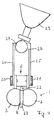
In den Fig. 8 und 9 ist ein alternatives Befestigungssystem der Stromschienen auf dem Untergrund dargestellt. Dargestellt ist die Befestigung einer Stromschiene in ihrem Endbereich. Hierzu wird auf die äußeren Stäbe (2, 3) der Stromschiene jeweils eine im Querschnitt C-förmige Hülse (30) aufgesteckt. Die Hülsen (30) werden mit den Stäben (2, 3) der Stromschiene durch lediglich angedeutete Schrauben (31) verbunden, die durch nicht dargestellte Bohrungen mit Innengewinde auf die Staboberfläche geschraubt werden. Den Schraubenbohrungen (31) gegenüber sind in den Hülsen weitere Bohrungen (32) vorgesehen, die ebenfalls ein Innengewinde aufweisen. In das Innengewinde der Bohrungen (32) werden wiederum lediglich angedeutete Schrauben (33) eingeschraubt, die in Bohrungen eines Sockels (34) geführt sind. Mit Hilfe der Schrauben (33) wird der Sockel (34) mit den Hülsen (30) fest verbunden. In die der Stromschiene gegenüberliegende Fläche (35) des Sockels (34) ist eine nicht näher dargestellte Sackbohrung eingebracht. In dieser Sackbohrung steckt der Schraubenbolzen einer lediglich angedeuteten Holzschraube (36). Die Holzschraube (36) wird zuvor im Untergrund (37), z. B. der Wand verdübelt. Dann wird der Sockel (34) mit der Sackbohrung auf den Schraubenbolzen der Schraube (36) aufgeschoben. Seitlich im Sockel (34) ist eine zur Sackbohrung rechtwinklige weitere Bohrung vorgesehen, die in der Sackbohrung mündet. Die Bohrung verfügt ebenfalls über ein Innengewinde, in das eine Madenschraube einschraubbar ist, die sich bei auf die Holzschraube aufgesetztem Sockel (34) gegen den Schraubenbolzen der Holzschraube (36) andrückt und den Sockel auf dem Untergrund fixiert. Die Hülsen können über nicht dargestellte, sondern lediglich angedeutete Anschlußbuchsen für die Stromversorgung verfügen. Die Hülsen (30) können an jeder beliebigen Stelle der Stromschiene befestigt sein. Dort können sie mit Hilfe des Sockels (34) am Untergrund befestigt werden. Sie können jedoch auch ohne den Sockel als Verbindungselemente zweier miteinander fluchtender Stromschienen dienen. Darüberhinaus ist es möglich, die Stromschiene mit Hilfe der Hülsen (30), z. B. von der Decke abzuhängen. Es ist auch möglich, zwei miteinander fluchtende Hülsen (30) mit Hilfe eines flexiblen Zwischenstücks miteinander zu verbinden. Auf diese Weise können zwei Stromschienen so aneinander befestigt werden, daß sie um einen beliebigen Winkel gegeneinander versetzt werden können.8 and 9, an alternative fastening system for the busbars on the ground is shown. The fastening of a busbar in its end region is shown. To do this, each of the outer bars (2, 3) of the busbar a sleeve (30) with a C-shaped cross section is attached. The sleeves (30) are connected to the bars (2, 3) of the conductor rail by only indicated screws (31), which are screwed onto the bar surface through holes, not shown, with an internal thread. Opposite the screw holes (31), further holes (32) are provided in the sleeves, which also have an internal thread. In turn, only indicated screws (33) are screwed into the internal thread of the bores (32), which are guided in bores of a base (34). With the help of the screws (33), the base (34) is firmly connected to the sleeves (30). A blind hole (not shown) is made in the surface (35) of the base (34) opposite the busbar. The screw bolt of a merely indicated wood screw (36) is inserted in this blind hole. The wood screw (36) is previously in the underground (37), for. B. wall pegged. Then the base (34) with the blind hole is pushed onto the screw bolt of the screw (36). At the side of the base (34) there is a further hole at right angles to the blind hole, which opens into the blind hole. The bore also has an internal thread into which a grub screw can be screwed, which, when the base (34) is placed on the wood screw, rests against the screw bolt of the wood screw (36) presses and the base is fixed on the surface. The sleeves can have not shown, but only indicated connection sockets for the power supply. The sleeves (30) can be attached at any point on the busbar. There they can be attached to the base using the base (34). However, they can also serve as connecting elements of two aligned busbars without the base. In addition, it is possible to use the sleeves (30), for. B. hanging from the ceiling. It is also possible to connect two sleeves (30) aligned with one another with the aid of a flexible intermediate piece. In this way, two busbars can be attached to each other so that they can be offset from each other by any angle.
Ein erfindungsgemäßes Beleuchtungssystem wird folgendermaßen aufgebaut:
An einer Wand oder einer Decke werden in Längsrichtung miteinander fluchtende Adapter (8) befestigt. Auf diesen Adaptern (8) werden Stromschienen (1) befestigt. Die Stromanschlüsse der Niedervolt-Spannungsquelle werden an zwei Enden (16 und 17) eines der Adapter, z. B. mit Hilfe der Schrauben (20 und 21) befestigt. Auf die von dem Untergrund abgewandte Seite der Stromschiene (1) wird ein mit einem Beleuchtungskörper (23) bestückter Adapter (8) aufgesetzt, so daß der Stromkreis geschlossen ist. Mehrere solcher Schienen können auf der Decke bzw. der Wand angeorndet werden, wobei zur Erzeugung verschiedenster Beleuchtungskonfigurationen die Beleuchtungskörper auf den Stromschienen versetzt werden können.A lighting system according to the invention is constructed as follows:
Adapters (8) which are aligned with one another in the longitudinal direction are fastened to a wall or a ceiling. Busbars (1) are attached to these adapters (8). The power connections of the low-voltage voltage source are at two ends (16 and 17) of one of the adapters, e.g. B. with the screws (20 and 21). On the side of the The busbar (1) is fitted with an adapter (8) equipped with a lighting fixture (23), so that the circuit is closed. Several such rails can be arranged on the ceiling or on the wall, and the lighting elements can be moved on the conductor rails in order to produce a wide variety of lighting configurations.
Claims (13)
- Low-voltage lighting system comprising at least one contact rail (1) fixed at the underground and lighting bodies (23) filed thereto via adapters (8), the contact rail (1) comprises at least two parallel bars (2, 3, 7) of magnetic material on different electrical potentials, the contact faces of the bars (2, 3, 7) are arranged in one plane adjacent to each other and the adapters (8) include two electrical and magnetical conducting contact faces (12, 13) arranged parallel in one plane for the current collecting from the adjacent contact faces of the bars (2, 3, 7), charcterized in that, said isolating layer (6) between the opposite faces (4, 5) of the adjacent bars (2, 3, 7) interconnect them to form said contact rail (1) and the contact faces (12, 13) of the adapters (8) are separated by an electrical non-conductive permanent magnet (11) and are fixed thereto.
- Low-voltage lighting system according to claim 1, characterized in that the isolating layer (6) comprises an adhesive tape.
- Low-Voltage lighting system according to claim 1 or 2, characterized in that the bars (2, 3, 7) are rectangular in cross-section.
- Low-voltage lighting system according to claim 1 or 2, characterized in that the bars (2, 3, 7) are round steel bars and the opposite faces (4, 5) of the bars (2, 3, 7) are flattened.
- Low-voltage lighting system according to any of the claims 1 to 4, characterized in that the magnet (11) is rectangular parallelepiped block having two opposite longitudinal faces each provided with steel plates (9, 10) fixed thereto, the edge of the steel paltes pointing to the contact rail (1) projecting over the longitudinal edges formed by the surface (14) of the blocks of the magnet (11) and forming a contact face (12, 13), each of the contacting elements (24, 25) loading to the lighting body (23) is attachable on one of the steel plates (16, 17).
- Low-voltage lighting system according to claim 1, characterized in that the ends (16, 17) of the steel plates (9, 10) projecting over said magnet (11) arranged between in longitudinal directions, the contact elements (24, 25) are attachable at the ends (16, 17) of the steel plate (9, 10) by screw means (20, 21).
- Low-voltage lighting system according to claim 5 or 6, characterized in that the contact elements (24, 25) are attachable by screw means (27, 28) at the lighting body (23).
- Low-voltage lighting system according to any of the preceding claims 1 to 7, characterized in that the isolating layer (6) between the bars (2, 3, 7) project over the plane formed by the aligned top surfaces of the bars (2, 3, 7) in form of a stem (23).
- Low-Voltage lighting system according to any of the preceding claims 1 to 7, characterized in that a stem (15) is arranged on the magnet (11) between the contact faces (12, 13) of the steel plates (9, 10) projecting over the plane formed by the contact faces.
- Low-voltage lighting system according to any of the preceding claims 1 to 9, characterized in that the contact rails (1) are fixable on magnetic adapters (8), comprising two steel plates (9, 10) in rectangular profile affixed to longitudinal opposite faces of a rectangular parallelepiped permanent magnet (11), the longitudinal edges (12, 13) of the steel plates (9, 10) are parallel to the longitudinal edges of the magnet (11) and provide the electrical and magnetical contact between the steel plates (9, 10) and the bars (2, 3, 7) of the contact rail (1).
- Low-voltage lighting system according to any of the claims 1 to 9, characterized in that jackets (30) partly enclosing the peripheral bars (2, 3) and pairwise opposite to each other are mountable and attachable on the bars (2, 3), each pair of jackets (30) is fixed on a socket (34), which is fixed to an underground (37).
- Low-voltage lighting system according to any of the claims 1 to 11, characterized in that the contact rail (1) consists of three parallel bars (2, 3, 7), each of the adjacent bars (2, 7; 3, 7) beeibg on a different electrical potential.
- Low-voltage lighting system according to any of the claims 1 to 11, characterized in that the contact rail (1) consists of eight parallel bars (2, 3, 7), the cross-section of the contact rail (1) is square and each of the faces of the square are formed by three bars (2, 3, 7).
Applications Claiming Priority (4)
| Application Number | Priority Date | Filing Date | Title |
|---|---|---|---|
| DE8711458U DE8711458U1 (en) | 1987-08-24 | 1987-08-24 | Magnetic adapter for power rail in low-voltage technology |
| DE8711457U DE8711457U1 (en) | 1987-08-24 | 1987-08-24 | Low-voltage power rail for magnetic adapter lights |
| DE8711458U | 1987-08-24 | ||
| DE8711457U | 1987-08-24 |
Publications (3)
| Publication Number | Publication Date |
|---|---|
| EP0304513A2 EP0304513A2 (en) | 1989-03-01 |
| EP0304513A3 EP0304513A3 (en) | 1990-02-28 |
| EP0304513B1 true EP0304513B1 (en) | 1995-03-08 |
Family
ID=25952001
Family Applications (1)
| Application Number | Title | Priority Date | Filing Date |
|---|---|---|---|
| EP87119214A Expired - Lifetime EP0304513B1 (en) | 1987-08-24 | 1987-12-24 | Low-voltage lighting system |
Country Status (2)
| Country | Link |
|---|---|
| EP (1) | EP0304513B1 (en) |
| DE (1) | DE3751145D1 (en) |
Families Citing this family (3)
| Publication number | Priority date | Publication date | Assignee | Title |
|---|---|---|---|---|
| DE29514672U1 (en) * | 1995-09-13 | 1995-12-07 | LTS Licht & Leuchten GmbH, 88069 Tettnang | Conductor system |
| WO2007145446A2 (en) * | 2006-06-14 | 2007-12-21 | Kyung-Ho Yang | Lighting apparatus using magnet |
| US7402045B2 (en) * | 2006-09-20 | 2008-07-22 | United Technologies Corporation | Electrical interconnection having magnetic conductive elements |
Family Cites Families (2)
| Publication number | Priority date | Publication date | Assignee | Title |
|---|---|---|---|---|
| FR1400179A (en) * | 1963-07-03 | 1965-05-21 | Philips Nv | Improvements to fixings of electrical devices |
| FR1600124A (en) * | 1968-12-30 | 1970-07-20 |
-
1987
- 1987-12-24 EP EP87119214A patent/EP0304513B1/en not_active Expired - Lifetime
- 1987-12-24 DE DE3751145T patent/DE3751145D1/en not_active Expired - Fee Related
Also Published As
| Publication number | Publication date |
|---|---|
| EP0304513A3 (en) | 1990-02-28 |
| EP0304513A2 (en) | 1989-03-01 |
| DE3751145D1 (en) | 1995-04-13 |
Similar Documents
| Publication | Publication Date | Title |
|---|---|---|
| EP1284033B1 (en) | Conductor rail system | |
| EP1117162B1 (en) | Busbar system and connection arrangement to connect the busbars to the terminals of an installation apparatus | |
| EP1284034B1 (en) | Conductor rail system | |
| EP1016821A1 (en) | Strip lighting system comprising a support rail to be mounted to a wall or to a ceiling | |
| EP1284035B1 (en) | Supply track system | |
| EP1994614B1 (en) | Frame construction for a switchgear cabinet, switchgear cabinet and construction kit for the switchgear cabinet | |
| DE4124066C2 (en) | Electric lighting system | |
| EP0466043B1 (en) | Distribution installation with at least two rows of electrical apparatus of a narrow type | |
| DE4312617A1 (en) | Electrical switch panel, especially for medium-voltage installations | |
| EP0304513B1 (en) | Low-voltage lighting system | |
| DE29814339U1 (en) | Lighting system | |
| DE9215527U1 (en) | Connector for busbars | |
| DE19706865C2 (en) | Track adapter | |
| DE2304639C3 (en) | Socket arrangement for electrical plug couplings | |
| DE3811459A1 (en) | KIT FOR A BUSBAR SYSTEM | |
| DE3806241A1 (en) | Installation device for low-voltage luminaires | |
| DE69312907T2 (en) | BUS-BAR SYSTEM | |
| WO2007033946A1 (en) | Busbar system for electrical switchgear | |
| DE8910975U1 (en) | Electrical ballast for fluorescent lamps | |
| DE19750100A1 (en) | Connection arrangement for current rails | |
| DE202006020037U1 (en) | Frame construction for a control cabinet, control cabinet and kit for the control cabinet | |
| AT356213B (en) | DEVICE FOR THE CONTINUOUS CONNECTION OF A MOUNTING RAIL WITH A LUMINAIRE BAR OF A FLUORESCENT LAMP | |
| DE2005953B2 (en) | Electrical street lights connection unit - has plastics half-housings fitted with dovetailed protrusions at ends for retaining contact terminals, bridges and bus=bars | |
| DE4312712A1 (en) | Device for current transmission (electricity transmission) | |
| DE1690374C (en) | Switch with screwless conductor connection terminals |
Legal Events
| Date | Code | Title | Description |
|---|---|---|---|
| PUAI | Public reference made under article 153(3) epc to a published international application that has entered the european phase |
Free format text: ORIGINAL CODE: 0009012 |
|
| AK | Designated contracting states |
Kind code of ref document: A2 Designated state(s): AT BE CH DE ES FR GB GR IT LI LU NL SE |
|
| RBV | Designated contracting states (corrected) |
Designated state(s): DE |
|
| PUAL | Search report despatched |
Free format text: ORIGINAL CODE: 0009013 |
|
| AK | Designated contracting states |
Kind code of ref document: A3 Designated state(s): DE |
|
| 17P | Request for examination filed |
Effective date: 19900526 |
|
| 17Q | First examination report despatched |
Effective date: 19930120 |
|
| GRAA | (expected) grant |
Free format text: ORIGINAL CODE: 0009210 |
|
| AK | Designated contracting states |
Kind code of ref document: B1 Designated state(s): DE |
|
| REF | Corresponds to: |
Ref document number: 3751145 Country of ref document: DE Date of ref document: 19950413 |
|
| PLBE | No opposition filed within time limit |
Free format text: ORIGINAL CODE: 0009261 |
|
| STAA | Information on the status of an ep patent application or granted ep patent |
Free format text: STATUS: NO OPPOSITION FILED WITHIN TIME LIMIT |
|
| 26N | No opposition filed | ||
| PGFP | Annual fee paid to national office [announced via postgrant information from national office to epo] |
Ref country code: DE Payment date: 20010928 Year of fee payment: 14 |
|
| PG25 | Lapsed in a contracting state [announced via postgrant information from national office to epo] |
Ref country code: DE Free format text: LAPSE BECAUSE OF NON-PAYMENT OF DUE FEES Effective date: 20020702 |