EP0303797A2 - Cylinder lock with electric switch device - Google Patents
Cylinder lock with electric switch device Download PDFInfo
- Publication number
- EP0303797A2 EP0303797A2 EP19880109853 EP88109853A EP0303797A2 EP 0303797 A2 EP0303797 A2 EP 0303797A2 EP 19880109853 EP19880109853 EP 19880109853 EP 88109853 A EP88109853 A EP 88109853A EP 0303797 A2 EP0303797 A2 EP 0303797A2
- Authority
- EP
- European Patent Office
- Prior art keywords
- cylinder
- pin
- contact element
- plunger
- cylinder lock
- Prior art date
- Legal status (The legal status is an assumption and is not a legal conclusion. Google has not performed a legal analysis and makes no representation as to the accuracy of the status listed.)
- Granted
Links
Images

Classifications
-
- H—ELECTRICITY
- H01—ELECTRIC ELEMENTS
- H01H—ELECTRIC SWITCHES; RELAYS; SELECTORS; EMERGENCY PROTECTIVE DEVICES
- H01H27/00—Switches operated by a removable member, e.g. key, plug or plate; Switches operated by setting members according to a single predetermined combination out of several possible settings
- H01H27/06—Key inserted and then turned to effect operation of the switch
Definitions
- the invention relates to a cylinder lock with an electrical switch arrangement, in particular for mounting on a printed circuit board, comprising a pot-shaped housing with at least one fixed contact element and at least one movable contact element, an actuating element for adjusting the movable contact element between a non-contact position and a contact position and one by a key unlockable lock cylinder rotatably mounted in the housing, which is rotatably connected to the actuating element.
- Such a cylinder lock is known for example from DE-OS 34 12 430. With such cylinder locks, the commissioning of electrical devices, for example electronic data processing devices, can be secured. The simultaneous actuation of a mechanical bolt, for example the unlocking or locking of a device housing is with the in DE-OS 34 12 430 described cylinder lock is not possible.
- Cylinder locks with mechanical and electrical locking functions are known, for example, as so-called ignition locks.
- mechanical unlocking for example of the steering wheel of a vehicle
- an electrical switch arrangement is unlocked, which is actuated when the key is turned further in the same direction in order to close the ignition circuit. In these cases, however, the mechanical and electrical closing function are coupled so that the electrical switch arrangement cannot be operated without the mechanical unlocking.
- the invention has for its object to develop a cylinder lock of the type mentioned with simple means so that it has an electrical and a mechanical locking function, the two locking functions should be separate.
- the locking cylinder has at its end remote from the key an axially directed extension, which is associated with a plunger axially displaceably mounted in the housing, and that one of the parts (extension, plunger) rotates the extension into an axial movement of the plunger converting control cam and the other part (plunger, shoulder) has a driver interacting with the control cam, the control cam extending over a rotation angle range outside the rotation angle range of the locking cylinder required for the adjustment of the movable contact element.
- a mechanical latch can be actuated via the plunger.
- the device can be put into operation on the one hand with the same lock and, on the other hand, the housing of the device can be unlocked, for example, if it has to be opened for maintenance purposes. Due to the separate rotation angle ranges of the locking cylinder for the electrical function on the one hand and the mechanical function on the other hand, these functions can be separated so that, for example, the operator receives his own key, with which he can only operate the electrical switch arrangement, while a maintenance technician receives a general key , with which he can perform both the electrical and the mechanical locking function.
- the position of the locking cylinder corresponding to the contact-free position of the movable contact element lies between the angle of rotation range required for the adjustment of the movable contact element and the angle of rotation encompassing the control curve.
- the axial arrangement of the mechanical actuating elements (extension, plunger) relative to the locking cylinder enables a very space-saving arrangement in cases in which the cylinder lock is to be soldered onto a circuit board, for example. In this case, it is sufficient to drill a hole in the circuit board through which the mechanical closing movement can take place.
- the approach is formed by a cylindrical pin and the plunger by a coaxially surrounding socket rotatably mounted in the housing base.
- the control cam consists of a helical groove in the circumferential surface of the pin or the wall of the socket bore receiving it, while the driver is formed by a pin intended to engage the groove on the other part (socket, pin).
- the helical groove merges at one of its ends into an annular groove section. This enables the cylinder lock and thus the cylindrical pin to be rotated to perform the electrical locking function without the sleeve being axially displaced and thus the mechanical locking function being performed.
- an axially parallel groove is expediently formed in the wall of the bush bore and is connected to the other end of the annular groove section.
- the socket can be pushed onto the pin and secured during assembly of the cylinder lock relative to the lock cylinder so that the pin can no longer get into the axially parallel groove, but can only move within the helical groove and the annular groove section.
- the socket is thus secured on the pin.
- the helical groove and the annular groove section could also be formed on the surface of the pin. In this case, the pin could be inserted into a radial bore in the bushing and fixed in a position in which it engages in the groove.
- the groove forming the control cam extends for the purpose moderately over an angle of rotation range of the locking cylinder of approximately 180 °, while the annular groove section can extend over an angle of rotation range of approximately 90 °, which enables a sufficiently safe actuation of the electrical switch arrangement.
- a cam In addition to the helical cam, a cam would also be conceivable, which has a profile in the axial direction and would be formed on an end face of the extension pointing in the axial direction.
- FIG. 1 shows a switch arrangement, generally designated 10, having a cylinder lock with a switch housing 12, comprising a first lower housing part 14, in which a second upper housing part 16 is clipped in a manner not shown.
- Fixed contact pins 20 are arranged on the bottom 18 of the lower housing part 14 and are soldered into corresponding grid openings in a printed circuit board 22.
- a cylinder lock 24 with a lock cylinder 26 is arranged, which can be rotated by means of a key 28.
- the locking cylinder 26 carries at its lower end an axially directed pin-shaped extension 30 which is provided with a radial pin 32 near the locking cylinder. This engages in a complementary recess of an actuating element 34 in order to rotate it when the locking cylinder 26 rotates.
- the actuating element 34 is rotatably mounted in the lower housing part 14 by means of a radial flange 36 and has a radial nose 38, which serves to press a movable contact element 40 against a fixed contact element 20, as shown in FIG to establish an electrical switching connection. This position is designated by 1 in FIG.
- a bushing 42 is slid onto the pin 30 coaxially with the latter and is axially displaceable but non-rotatably mounted in the bottom of the lower housing part 14.
- the Protection against rotation is provided by two ribs 44 on the outer circumference of the bushing 42, which engage in complementary grooves in the bottom of the lower housing part 14.
- a plurality of grooves are formed in the wall of the bore 46 of the bushing 42, which grooves are intended to engage a radial pin 48 connected to the extension 30.
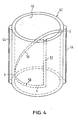
- a first annular groove section 50 extends over a little more than 90 °. At one end it is connected to an axially parallel groove 52 which extends to the free edge of the bushing 42.
- the groove section 50 merges into a helical groove section 54 which extends over approximately 180 °.
- the pin 48 slides through the groove section 52 when the bush 42 is pushed onto the pin 30. If the bushing 42 is then secured in the lower housing part 14 against rotation and the cylinder lock is fixed in the housing 12, the pin 48 on the extension 30 assumes a position within the groove sections 50, 54 and can no longer reach the groove 52, so that the socket 42 sits captively on the pin 30.
- the pin 48 passes through the groove section 50 between the positions 0 and 1 indicated in FIG. 4. An axial adjustment of the bush 42 on the pin 30 takes place because of the position of the groove section 50 does not take place in a plane normal to the axis. If, on the other hand, the locking cylinder 26 is adjusted between the positions designated 0 and 2 in FIGS. 3 and 4, the pin 48 passes through the groove section 54 when the extension 30 is rotated by approximately 180 °. The bushing 42 is forced out of the position shown in FIG the position shown by solid lines in the position shown by dash-dotted lines. This stroke of the socket 42 can not be used to actuate a Darge provided mechanical bolt can be used.
- the socket can be firmly connected to the bolt so that the bolt can be actively adjusted in both directions.
- a corresponding bolt rests against the bush 42 under spring pressure and, due to the spring action, follows the bush 42 when it is again adjusted in the direction of the lower housing part 14 or the locking cylinder 26.
- the locking cylinder can be designed so that rotation between positions 0 and 1 or 0 and 2 can only be achieved with different keys. In another embodiment it can be provided that the rotation between positions 0 and 1 is possible with a key, while all positions can be reached with a master key.
- a maintenance technician can access all systems with the master key, for example, and can both open the device and put it into operation .
Landscapes
- Lock And Its Accessories (AREA)
- Push-Button Switches (AREA)
Abstract
Description
Die Erfindung betrifft ein Zylinderschloß mit elektrischer Schalteranordnung, insbesondere zur Montage auf einer Leiterplatte, umfassend ein topfförmigees Gehäuse mit mindestens einem feststehenden Kontaktelement und mindestens einem beweglichen Kontaktelement, einem Betätigungselement zum Verstellen des beweglichen Kontaktelements zwischen einer kontaktfreien Stellung und einer Kontaktstellung und einen durch einen Schlüssel entsperrbaren in dem Gehäuse drehbar gelagerten Schließzylinder, der mit dem Betätigungselement drehfest verbunden ist.The invention relates to a cylinder lock with an electrical switch arrangement, in particular for mounting on a printed circuit board, comprising a pot-shaped housing with at least one fixed contact element and at least one movable contact element, an actuating element for adjusting the movable contact element between a non-contact position and a contact position and one by a key unlockable lock cylinder rotatably mounted in the housing, which is rotatably connected to the actuating element.
Ein derartiges Zylinderschloß ist beispielsweise aus der DE-OS 34 12 430 bekannt. Mit derartigen Zylinderschlössern kann die Inbetriebnahme von elektrischen Geräten, beispielsweise elektronischen Datenverarbeitungseinrichtungen, gesichert werden. Die gleichzeitige Betätigung eines mechanischn Riegels, beispielsweise die Entriegelung oder Veriegelung eines Gerätegehäuses ist mit dem in der DE-OS 34 12 430 beschriebenen Zylinderschloß nicht möglich. Zylinderschlösser mit mechanischer und elektrischer Schließfunktion sind beispielsweise als sogenannte Zündschlösser bekannt. In den meisten Fällen erfolgt dabei nach dem Einführen des Schlüssels in den Schließzylinder zunächst eine mechanische Entriegelung z.B. des Lenkrades eines Fahrzeuges und gleichzeitig ein Entsperren einer elektrischen Schalteranordnung, die beim weiteren Drehen des Schlüssels in der gleichen Richtung im Sinne einer Schliessung des Zündstromkreises betätigt wird. In diesen Fällen sind jedoch die mechanische und elektrische Schließfunktion so gekoppelt, daß die elektrische Schalteranordnung nicht ohne die mechanische Entsperrung betätigt werden kann.Such a cylinder lock is known for example from DE-OS 34 12 430. With such cylinder locks, the commissioning of electrical devices, for example electronic data processing devices, can be secured. The simultaneous actuation of a mechanical bolt, for example the unlocking or locking of a device housing is with the in DE-OS 34 12 430 described cylinder lock is not possible. Cylinder locks with mechanical and electrical locking functions are known, for example, as so-called ignition locks. In most cases, after the key has been inserted into the lock cylinder, mechanical unlocking, for example of the steering wheel of a vehicle, is initially carried out and at the same time an electrical switch arrangement is unlocked, which is actuated when the key is turned further in the same direction in order to close the ignition circuit. In these cases, however, the mechanical and electrical closing function are coupled so that the electrical switch arrangement cannot be operated without the mechanical unlocking.
Der Erfindung liegt die Aufgabe zugrunde, ein Zylinderschloß der eingangs genannten Art mit einfachen Mitteln so weiterzubilden, daß es eine elektrische und eine mechanische Schließfunktion aufweist, wobei die beiden Schließfunktionen voneinander getrennt sein sollen.The invention has for its object to develop a cylinder lock of the type mentioned with simple means so that it has an electrical and a mechanical locking function, the two locking functions should be separate.
Diese Aufgabe wird erfindungsgemäß dadurch gelöst, daß der Schließzylinder an seinem schlüsselfernen Ende einen axial gerichteten Ansatz aufweist, dem ein im Gehäuse axial verschiebbar gelagerter Stössel zugeordnet ist, und daß eines der Teile (Ansatz, Stößel) eine die Drehbewegung des Ansatzes in eine axiale Bewegung des Stößels umsetzende Steuerkurve und das jeweils andere Teil (Stößel, Ansatz) einen mit der Steuerkurve zusammenwirkenden Mitnehmer aufweist, wobei sich die Steuerkurve über einen Drehwinkelbereich außerhalb des für die Verstellung des beweglichen Kontaktelementes erforderlichen Drehwinkelbereiches des Schließzylinders erstreckt.This object is achieved in that the locking cylinder has at its end remote from the key an axially directed extension, which is associated with a plunger axially displaceably mounted in the housing, and that one of the parts (extension, plunger) rotates the extension into an axial movement of the plunger converting control cam and the other part (plunger, shoulder) has a driver interacting with the control cam, the control cam extending over a rotation angle range outside the rotation angle range of the locking cylinder required for the adjustment of the movable contact element.
Über den Stößel kann beispielsweise ein mechanischer Riegel betätigt werden. Wird das erfindungsgemäße Zylinderschloß beispielsweise in elektrischen oder elektronischen Geräten eingesetzt, so kann mit demselben Schloß einerseits das Gerät in Betrieb genommen werden und andererseits beispielsweise das Gehäuse des Gerätes entriegelt werden, wenn es für Wartungszwecke geöffnet werden muß. Aufgrund der getrennten Drehwinkelbereiche des Schließzylinders für die elektrische Funktion einerseits und die mechanische Funktion andererseits lassen sich diese Funktionen dabei jedoch so trennen, daß beispielsweise die Bedienungsperson einen eigenen Schlüssel erhält, mit dem sie nur die elektrische Schalteranordnung betätigen kann, während ein Wartungstechniker einen Generalschlüssel erhält, mit dem er sowohl die elektrische als auch die mechanische Schließfunktion ausüben kann.For example, a mechanical latch can be actuated via the plunger. If the cylinder lock according to the invention is used, for example, in electrical or electronic devices, the device can be put into operation on the one hand with the same lock and, on the other hand, the housing of the device can be unlocked, for example, if it has to be opened for maintenance purposes. Due to the separate rotation angle ranges of the locking cylinder for the electrical function on the one hand and the mechanical function on the other hand, these functions can be separated so that, for example, the operator receives his own key, with which he can only operate the electrical switch arrangement, while a maintenance technician receives a general key , with which he can perform both the electrical and the mechanical locking function.
Bei einer bevorzugten Ausführung liegt dabei die der kontaktfreien Stellung des beweglichen Kontaktelementes entsprechende Stellung des Schließzylinders zwischen dem zur Verstellung des beweglichen Kontaktelementes erforderlichen und dem die Steuerkurve umfassenden Drehwinkelbereich. Damit wird durch eine Drehung des Schlüssels und des Schließzylinders in der einen Richtung nur die elektrische Schließfunktion ausgeübt, während ausgehend von der Anfangslage eine Drehung des Schließzylinders in der entgegengesetzten Richtung die mechanische Verriegelung oder Entriegelung bewirkt.In a preferred embodiment, the position of the locking cylinder corresponding to the contact-free position of the movable contact element lies between the angle of rotation range required for the adjustment of the movable contact element and the angle of rotation encompassing the control curve. Thus, by rotating the key and the locking cylinder in one direction, only the electrical locking function is carried out, while starting from the initial position, rotating the locking cylinder in the opposite direction effects the mechanical locking or unlocking.
Die axiale Anordnung der mechanischen Betätigungselemente (Ansatz, Stößel) relativ zum Schließzylinder ermöglicht eine sehr raumsparende Anordnung in den Fällen, in denen das Zylinderschloß beispielsweise auf eine Leiterplatte aufgelötet werden soll. In diesem Falle genügt es, ein Loch in die Leiterplatte zu bohren, durch die hindurch die mechanische Schließbewegung erfolgen kann. In einer sehr kompakten bevorzugten Ausführungsform der Erfindung ist der Ansatz von einem zylindrischen Zapfen und der stößel von einer diesen koaxial umgebenden drehfest im Gehäuseboden gelagerten Buchse gebildet. Die Steuerkurve besteht aus einer schraubenlinienförmigen Nut in der Umfangsfläche des Zapfens oder der Wand der diesen aufnehmenden Buchsenbohrung, während der Mitnehmer von einem zum Eingriff in die Nut bestimmten Stift an dem jeweils anderen Teil (Buchse, Zapfen) gebildet ist. Die schraubenlinienförmige Nut geht dabei an einem ihrer Enden in einen kreisringförmigen Nutabschnitt über. Dieser ermöglicht eine Drehung des Zylinderschlosses und damit des zylindrischen Zapfens für die Ausübung der elektrischen Schließfunktion, ohne daß dabei die Buchse axial verschoben und damit die mechanische Schließfunktion ausgeübt wird. Um bei Anordnung des Stiftes an dem Zapfen die Buchse auf dem Zapfen montieren zu können, ist zweckmäßigerweise in der Wand der Buchsenbohrung eine achsparallele Nut ausgebildet, die mit dem anderen Ende des kreisringförmigen Nutabschnittes verbunden ist. Auf diese Weise kann die Buchse auf den Zapfen aufgeschoben und bei der Montage des Zylinderschlosses relativ zum Schließzylinder so gesichert werden, daß der Stift nicht mehr in die achsparallele Nut gelangen,sondern sich nur noch innerhalb der schraubenlinienförmigen Nut und des kreisringförmigen Nutabschnittes bewegen kann. Die Buchse ist damit auf dem Zapfen gesichert. Alternativ dazu könnten die schraubenlinienförmigen Nut und der kreisringförmige Nutabschnitt auch auf der Oberfläche des Zapfens ausgebildet sein. Der Stift könnte in diesem Falle in eine radiale Bohrung in der Buchse eingesetzt und in einer Stellung fixiert werden, in der er in die Nut eingreift.The axial arrangement of the mechanical actuating elements (extension, plunger) relative to the locking cylinder enables a very space-saving arrangement in cases in which the cylinder lock is to be soldered onto a circuit board, for example. In this case, it is sufficient to drill a hole in the circuit board through which the mechanical closing movement can take place. In a very compact preferred embodiment of the invention, the approach is formed by a cylindrical pin and the plunger by a coaxially surrounding socket rotatably mounted in the housing base. The control cam consists of a helical groove in the circumferential surface of the pin or the wall of the socket bore receiving it, while the driver is formed by a pin intended to engage the groove on the other part (socket, pin). The helical groove merges at one of its ends into an annular groove section. This enables the cylinder lock and thus the cylindrical pin to be rotated to perform the electrical locking function without the sleeve being axially displaced and thus the mechanical locking function being performed. In order to be able to mount the bush on the pivot when the pin is arranged on the pivot, an axially parallel groove is expediently formed in the wall of the bush bore and is connected to the other end of the annular groove section. In this way, the socket can be pushed onto the pin and secured during assembly of the cylinder lock relative to the lock cylinder so that the pin can no longer get into the axially parallel groove, but can only move within the helical groove and the annular groove section. The socket is thus secured on the pin. Alternatively, the helical groove and the annular groove section could also be formed on the surface of the pin. In this case, the pin could be inserted into a radial bore in the bushing and fixed in a position in which it engages in the groove.
Um einen genügend großen Stellweg für den Stößel zu haben, erstreckt sich die die Steuerkurve bildende Nut zweck mäßigerweise über einen Drehwinkelbereich des Schließzylinders von ca. 180°, während der kreisringförmige Nutabschnitt sich über einen Drehwinkelbereich von ca. 90° erstrecken kann,der eine ausreichend sichere Betätigung der elektrischen Schalteranordnung ermöglicht.In order to have a sufficiently large travel for the tappet, the groove forming the control cam extends for the purpose moderately over an angle of rotation range of the locking cylinder of approximately 180 °, while the annular groove section can extend over an angle of rotation range of approximately 90 °, which enables a sufficiently safe actuation of the electrical switch arrangement.
Neben der schraubenlinienförmigen Steuerkurve wäre auch eine Steuerkurve denkbar, die ein Profil in axialer Richtung aufweist und an einer in axialer Richtung weisenden Stirnfläche des Ansatzes ausgebildet wäre.In addition to the helical cam, a cam would also be conceivable, which has a profile in the axial direction and would be formed on an end face of the extension pointing in the axial direction.
Weitere Merkmale und Vorteile der Erfindung ergeben sich aus der folgenden Beschreibung, welche in Verbindung mit den beigefügten Zeichnungen die Erfindung anhand eines Ausführungsbeispieles erläutert. Es zeigen:
- Figur 1 einen die Schließzylinderachse enthaltenden Schnitt durch eine Zylinderschloßanordnung gemäß der Erfindung,
Figur 2 einen schematischen Schnitt durch die Buchse und den Zapfen längs Linie II-II in Fig. 1,- Figur 3 eine schematische Draufsicht auf das Zylinderschloß in Richtung des Pfeils A in Fig. 1 und
- Figur 4 eine schematische perspektivische Darstellung der Buchse mit dem Verlauf der an der Buchseninnenwand ausgebildeten Nut.
- FIG. 1 shows a section through a cylinder lock arrangement according to the invention containing the lock cylinder axis,
- FIG. 2 shows a schematic section through the bush and the pin along line II-II in FIG. 1,
- Figure 3 is a schematic plan view of the cylinder lock in the direction of arrow A in Fig. 1 and
- Figure 4 is a schematic perspective view of the socket with the course of the groove formed on the inner wall of the socket.
In Fig.1 erkennt man eine allgemein mit 10 bezeichnete Schalteranordnung mit Zylinderschloß mit einem Schaltergehäuse 12, umfassend ein erstes unteres Gehäuseteil 14, in das ein zweites oberes Gehäuseteil 16 in nicht dargestellter Weise eingeklipst ist. Am Boden 18 des unteren Gehäuseteils 14 sind feststehende Kontaktstifte 20 angeordnet, die in entsprechende Rasteröffnungen einer Leiterplatte 22 eingelötet sind.1 shows a switch arrangement, generally designated 10, having a cylinder lock with a
In dem oberen Gehäuseteil 16 ist ein Zylinderschloß 24 mit einem Schließzylinder 26 angeordnet, der mittels eines Schlüssels 28 verdreht werden kann. Der Schließzylinder 26 trägt an seinem unteren Ende einen axial gerichteten zapfenförmigen Fortsatz 30, der nahe dem Schließzylinder mit einem radialen Stift 32 versehen ist. Dieser greift in eine komplementäre Vertiefung eines Betätigungselementes 34, um dieses bei einer Drehung des Schließzylinders 26 mitzudrehen. Das Betätigungselement 34 ist mittels eines radialen Flansches 36 in dem unteren Gehäuseteil 14 drehbar gelagert und weist eine radiale Nase 38 auf, die dazu dient, ein bewegliches Kontaktelement 40 an ein feststehendes Kontaktelement 20 anzudrücken, wie dies in Fig. 1 dargestellt ist, um somit eine elektrische Schaltverbindung herzustellen. Diese Position ist in Fig. 3 auf dem den Drehwinkelbereich des Schließzylinders wiedergebenden Kreisbogen mit 1 bezeichnet. Wird das Betätigungselement 34 aus der in der Fig. 1 dargestellten Stellung um 90° verdreht, so wird das bewegliche Kontaktelement 40 frei und kann aufgrund seiner federelastischen Vorspannung von dem feststehenden Kontaktelement 20 abheben, so daß die Schaltverbindung unterbrochen ist. Diese der kontaktfreien Stellung des beweglichen Kontaktelementes 40 entsprechende Stellung des Schließzylinders ist in Fig. 3 mit 0 angegeben.In the
Auf den Zapfen 30 ist koaxial zu diesem eine Buchse 42 aufgeschoben, die axial verschiebbar,jedoch drehfest in dem Boden des unteren Gehäuseteils 14 gelagert ist. Die Sicherung gegen eine Verdrehung erfolgt durch zwei Rippen 44 an dem Außenumfang der Buchse 42, die in komplementäre Nuten in dem Boden des Gehäuseunterteils 14 eingreifen. In der Wand der Bohrung 46 der Buchse 42 sind mehrere Nuten ausgebildet, die zum Eingriff eines mit dem Ansatz 30 verbundenen radialen Stiftes 48 bestimmt sind. Ein erster kreisringförmiger Nutabschnitt 50 erstreckt sich über etwas mehr als 90°. An seinem einen Ende ist er mit einer achsparallelen Nut 52 verbunden, die sich bis zum freien Rand der Buchse 42 erstreckt. An seinem anderen Ende geht der Nutabschnitt 50 in einen schraubenlinienförmigen Nutabschnitt 54 über, der sich über ca. 180° erstreckt. Durch den Nutabschnitt 52 gleitet der stift 48, wenn die Buchse 42 auf den Zapfen 30 aufgeschoben wird. Wird die Buchse 42 anschließend in dem Gehäuseunterteil 14 gegen ein Verdrehen gesichert und das Zylinderschloß in dem Gehäuse 12 fixiert, so nimmt der Stift 48 an dem Ansatz 30 eine Position innerhalb der Nutabschnitte 50,54 ein und kann die Nut 52 nicht mehr erreichen, so daß die Buchse 42 unverlierbar auf dem Zapfen 30 sitzt.A
Wird der Schließzylinder 26 zwischen den Positionen 1 und 0 verstellt, so durchläuft der Stift 48 den Nutabschnitt 50 zwischen den auf in der Fig. 4 angedeuteten Positionen 0 und 1. Eine axiale Verstellung der Buchse 42 auf dem Zapfen 30 findet wegen der Lage des Nutabschnittes 50 in einer achsnormalen Ebene nicht statt. Wird dagegen der Schließzylinder 26 zwischen den in den Figuren 3 und 4 mit 0 und 2 bezeichneten Positionen verstellt, so durchläuft der Stift 48 bei der Drehung des Ansatzes 30 um ca. 180° den Nutabschnitt 54. Dabei wird die Buchse 42 zwangsweise aus der in der Fig. 1 durch ausgezogene Linien wiedergegebenen Stellung in die durch strichpunktierte Linien wiedergegebene Stellung verschoben. Dieser Hub der Buchse 42 kann zur Betätigung eines nicht darge stellten mechanischen Riegels verwendet werden. Dabei kann die Buchse fest mit dem Riegel verbunden werden, so daß der Riegel in beiden Richtungen aktiv verstellt werden kann. Es besteht jedoch auch die Möglichkeit, daß ein entsprechender Riegel unter Federdruck an der Buchse 42 anliegt und aufgrund der Federwirkung der Buchse 42 folgt, wenn diese wieder in Richtung auf das Gehäuseunterteil 14 bzw. den Schließzylinder 26hin verstellt wird.If the
Der Schließzylinder kann so ausgebildet sein, daß eine Drehung zwischen den Positionen 0 und 1 bzw. 0 und 2 nur mit unterschiedlichen Schlüsseln erreichbar ist. Bei einer anderen Ausführungsform kann vorgesehen sein, daß die Drehung zwischen den Positionen 0 und 1 mit einem Schlüssel möglich ist, während mit einem Generalschlüssel alle Stellungen erreichbar sind. Bei einem Einbau des Zylinderschlosses in einer EDV-Anlage wird es damit möglich, dem Benutzer der Anlage nur die Inbetriebnahme seiner Anlage zu erlauben, während ein Wartungstechniker beispielsweise mit dem Generalschlüssel Zugang zu allen Anlagen hat und sowohl das Gerät öffnen als auch in Betrieb nehmen kann.The locking cylinder can be designed so that rotation between
Claims (6)
Applications Claiming Priority (2)
| Application Number | Priority Date | Filing Date | Title |
|---|---|---|---|
| DE8711243U DE8711243U1 (en) | 1987-08-18 | 1987-08-18 | |
| DE8711243U | 1987-08-18 |
Publications (3)
| Publication Number | Publication Date |
|---|---|
| EP0303797A2 true EP0303797A2 (en) | 1989-02-22 |
| EP0303797A3 EP0303797A3 (en) | 1989-10-18 |
| EP0303797B1 EP0303797B1 (en) | 1993-05-26 |
Family
ID=6811194
Family Applications (1)
| Application Number | Title | Priority Date | Filing Date |
|---|---|---|---|
| EP88109853A Expired - Lifetime EP0303797B1 (en) | 1987-08-18 | 1988-06-21 | Cylinder lock with electric switch device |
Country Status (2)
| Country | Link |
|---|---|
| EP (1) | EP0303797B1 (en) |
| DE (2) | DE8711243U1 (en) |
Citations (5)
| Publication number | Priority date | Publication date | Assignee | Title |
|---|---|---|---|---|
| DE2027682A1 (en) * | 1970-06-05 | 1971-12-09 | Hans KoIb KG, 8000 München | Cylinder lock with axially movable lock cylinder |
| US3742161A (en) * | 1971-05-10 | 1973-06-26 | Brevets Neiman Soc D Expl Des | Electric switch assembly and combination thereof with safety locks |
| GB1362176A (en) * | 1970-11-21 | 1974-07-30 | Lucas Industries Ltd | Ignition switches |
| CH616481A5 (en) * | 1976-08-09 | 1980-03-31 | Dieter Reichert | Switch for door locks |
| US4634822A (en) * | 1985-11-15 | 1987-01-06 | Fort Lock Corporation | Multiple operation switch lock |
Family Cites Families (7)
| Publication number | Priority date | Publication date | Assignee | Title |
|---|---|---|---|---|
| DE835701C (en) * | 1951-03-10 | 1952-04-03 | W V D Bey Fa | Theft protection for bicycles and motorcycles |
| CH381303A (en) * | 1960-12-30 | 1964-08-31 | Weltrawo Ag | Key operated electrical switch |
| US4099395A (en) * | 1976-04-27 | 1978-07-11 | Roque Villareal Garza | Tumbler pin-type cylinder lock |
| DE2822098A1 (en) * | 1978-05-20 | 1979-11-22 | Daimler Benz Ag | ROTARY CYLINDER LOCK, ESPECIALLY FOR MOTOR VEHICLES |
| DE3034998C2 (en) * | 1980-09-17 | 1984-04-05 | Rafi Gmbh & Co Elektrotechnische Spezialfabrik, 7981 Berg | Authorization lock with several locking positions |
| DE3112293A1 (en) * | 1981-03-27 | 1982-10-07 | ddm hopt + schuler GmbH & Co KG, 7210 Rottweil | Key-operated switch |
| DE3412430A1 (en) * | 1984-04-03 | 1985-10-03 | Nixdorf Computer Ag, 4790 Paderborn | SWITCH ARRANGEMENT |
-
1987
- 1987-08-18 DE DE8711243U patent/DE8711243U1/de not_active Expired
-
1988
- 1988-06-21 EP EP88109853A patent/EP0303797B1/en not_active Expired - Lifetime
- 1988-06-21 DE DE8888109853T patent/DE3881298D1/en not_active Expired - Fee Related
Patent Citations (5)
| Publication number | Priority date | Publication date | Assignee | Title |
|---|---|---|---|---|
| DE2027682A1 (en) * | 1970-06-05 | 1971-12-09 | Hans KoIb KG, 8000 München | Cylinder lock with axially movable lock cylinder |
| GB1362176A (en) * | 1970-11-21 | 1974-07-30 | Lucas Industries Ltd | Ignition switches |
| US3742161A (en) * | 1971-05-10 | 1973-06-26 | Brevets Neiman Soc D Expl Des | Electric switch assembly and combination thereof with safety locks |
| CH616481A5 (en) * | 1976-08-09 | 1980-03-31 | Dieter Reichert | Switch for door locks |
| US4634822A (en) * | 1985-11-15 | 1987-01-06 | Fort Lock Corporation | Multiple operation switch lock |
Also Published As
| Publication number | Publication date |
|---|---|
| DE8711243U1 (en) | 1987-10-08 |
| EP0303797A3 (en) | 1989-10-18 |
| DE3881298D1 (en) | 1993-07-01 |
| EP0303797B1 (en) | 1993-05-26 |
Similar Documents
| Publication | Publication Date | Title |
|---|---|---|
| EP1636454B1 (en) | Electromechanical lock cylinder | |
| EP2070055B1 (en) | Electric operator control unit | |
| EP0183931A2 (en) | Remote control device for an electrical switch or a similar device | |
| DE2644312B1 (en) | Device for blocking a cylinder lock actuated locking bolt in a locked position | |
| EP1384633A1 (en) | Locking system for a motor vehicle | |
| EP0447818A1 (en) | Device for interrogation of angles of rotation of a locking cylinder in a locking system operated by keys | |
| DE3924230C2 (en) | Door locking device for use in a vehicle body | |
| EP1690272A1 (en) | Switching device and arrangement for detecting various positions of a door element | |
| EP1135284B1 (en) | Locking system, especially for motor vehicles | |
| DE112007000611B4 (en) | Electrical connector and electrical connector with different engagement and operative retention forces | |
| EP0768690B1 (en) | Pivotable actuator for a safety switch | |
| EP0235350B1 (en) | Switch, in particular for a motor vehicle | |
| DE2757544C3 (en) | Steering lock for automobiles | |
| EP0585541B1 (en) | Electric switch for speed control of motors | |
| DE3236190C2 (en) | Steering and ignition locks for motor vehicles | |
| EP0303797B1 (en) | Cylinder lock with electric switch device | |
| EP1183699B1 (en) | Contact assembly on a preselector | |
| DE2553610C3 (en) | Screw socket with protection against accidental contact, especially for lamps | |
| EP3819449A1 (en) | Motor vehicle lock | |
| DE1555886C3 (en) | Anti-theft devices for motor vehicles | |
| EP3540156A1 (en) | Handle bearing | |
| DE102021126433B3 (en) | Installation element for electrical connection units | |
| EP4012200B1 (en) | Spring-loaded detent bolt | |
| DE60206978T2 (en) | Improved steering lock for a motor vehicle | |
| DE102021000442B4 (en) | Door handle for actuating a door lock, in particular for a vehicle |
Legal Events
| Date | Code | Title | Description |
|---|---|---|---|
| PUAI | Public reference made under article 153(3) epc to a published international application that has entered the european phase |
Free format text: ORIGINAL CODE: 0009012 |
|
| AK | Designated contracting states |
Kind code of ref document: A2 Designated state(s): AT BE CH DE ES FR GB GR IT LI LU NL SE |
|
| RBV | Designated contracting states (corrected) |
Designated state(s): CH DE FR GB LI NL SE |
|
| PUAL | Search report despatched |
Free format text: ORIGINAL CODE: 0009013 |
|
| AK | Designated contracting states |
Kind code of ref document: A3 Designated state(s): CH DE FR GB LI NL SE |
|
| 17P | Request for examination filed |
Effective date: 19900321 |
|
| RAP3 | Party data changed (applicant data changed or rights of an application transferred) |
Owner name: SIEMENS NIXDORF INFORMATIONSSYSTEME AKTIENGESELLSC |
|
| 17Q | First examination report despatched |
Effective date: 19920131 |
|
| GRAA | (expected) grant |
Free format text: ORIGINAL CODE: 0009210 |
|
| AK | Designated contracting states |
Kind code of ref document: B1 Designated state(s): CH DE FR GB LI NL SE |
|
| PGFP | Annual fee paid to national office [announced via postgrant information from national office to epo] |
Ref country code: GB Payment date: 19930526 Year of fee payment: 6 |
|
| PGFP | Annual fee paid to national office [announced via postgrant information from national office to epo] |
Ref country code: SE Payment date: 19930622 Year of fee payment: 6 |
|
| REF | Corresponds to: |
Ref document number: 3881298 Country of ref document: DE Date of ref document: 19930701 |
|
| ET | Fr: translation filed | ||
| GBT | Gb: translation of ep patent filed (gb section 77(6)(a)/1977) |
Effective date: 19930804 |
|
| PLBE | No opposition filed within time limit |
Free format text: ORIGINAL CODE: 0009261 |
|
| STAA | Information on the status of an ep patent application or granted ep patent |
Free format text: STATUS: NO OPPOSITION FILED WITHIN TIME LIMIT |
|
| 26N | No opposition filed | ||
| PG25 | Lapsed in a contracting state [announced via postgrant information from national office to epo] |
Ref country code: GB Effective date: 19940621 |
|
| PG25 | Lapsed in a contracting state [announced via postgrant information from national office to epo] |
Ref country code: SE Effective date: 19940622 |
|
| PGFP | Annual fee paid to national office [announced via postgrant information from national office to epo] |
Ref country code: NL Payment date: 19940630 Year of fee payment: 7 |
|
| EUG | Se: european patent has lapsed |
Ref document number: 88109853.7 Effective date: 19950110 |
|
| GBPC | Gb: european patent ceased through non-payment of renewal fee |
Effective date: 19940621 |
|
| EUG | Se: european patent has lapsed |
Ref document number: 88109853.7 |
|
| PG25 | Lapsed in a contracting state [announced via postgrant information from national office to epo] |
Ref country code: NL Effective date: 19960101 |
|
| NLV4 | Nl: lapsed or anulled due to non-payment of the annual fee |
Effective date: 19960101 |
|
| PGFP | Annual fee paid to national office [announced via postgrant information from national office to epo] |
Ref country code: FR Payment date: 19960625 Year of fee payment: 9 |
|
| PGFP | Annual fee paid to national office [announced via postgrant information from national office to epo] |
Ref country code: CH Payment date: 19960920 Year of fee payment: 9 |
|
| PG25 | Lapsed in a contracting state [announced via postgrant information from national office to epo] |
Ref country code: LI Free format text: LAPSE BECAUSE OF NON-PAYMENT OF DUE FEES Effective date: 19970630 Ref country code: CH Free format text: LAPSE BECAUSE OF NON-PAYMENT OF DUE FEES Effective date: 19970630 |
|
| PGFP | Annual fee paid to national office [announced via postgrant information from national office to epo] |
Ref country code: DE Payment date: 19970820 Year of fee payment: 10 |
|
| REG | Reference to a national code |
Ref country code: CH Ref legal event code: PL |
|
| PG25 | Lapsed in a contracting state [announced via postgrant information from national office to epo] |
Ref country code: FR Free format text: LAPSE BECAUSE OF NON-PAYMENT OF DUE FEES Effective date: 19980227 |
|
| REG | Reference to a national code |
Ref country code: FR Ref legal event code: ST |
|
| REG | Reference to a national code |
Ref country code: FR Ref legal event code: ST |
|
| PG25 | Lapsed in a contracting state [announced via postgrant information from national office to epo] |
Ref country code: DE Free format text: LAPSE BECAUSE OF NON-PAYMENT OF DUE FEES Effective date: 19990401 |